Suchergebnisse für ""CH32V003""
verbinden. Um die Firmware für den Programmer zu flashen wechselt man in das Verzeichnis /home/mcu/ch32v003 /rvswdio_programmer und startet dort erst make und anschließend make flash: cd /home/mcu/ch32v003 /rvswdio_programmer make riscv-none-elf-gcc -E -P -x c -DTARGET_MCU=CH32V003 -DMCU_PACKAGE=1 -DTARGET_MCU_LD
in
„CH32V003: Selbstbauprogrammer und "Getting started"“
·
Projekte & Code
·
23.05.2025 10:39
für den CH32V003 flashen (wie es der Autor des Textes zu Beginn mit dem CH32V003 auch getan hat). Allerdings hat der ARDULINK- Programmer einen entscheidenden Haken: er ist schier unerträglich langsam. Für das Flashen
in
„CH32V003: Selbstbauprogrammer und "Getting started"“
·
Projekte & Code
·
22.05.2025 23:45
verbinden. Um die Firmware für den Programmer zu flashen wechselt man in das Verzeichnis /home/mcu/ch32v003 /rvswdio_programmer und startet dort erst make und anschließend make flash: cd /home/mcu/ch32v003 /rvswdio_programmer make riscv-none-elf-gcc -E -P -x c -DTARGET_MCU=CH32V003 -DMCU_PACKAGE=1 -DTARGET_MCU_LD
in
„CH32V003: Selbstbauprogrammer und "Getting started"“
·
Projekte & Code
·
20.06.2025 15:25
started 10 Geany 11 CIDE 12 Hallo Welt 13 Die Sache mit dem Makefile 13 Aufbau eines Makefiles für CH32V003 an einem Beispiel 14 Quelldateien für den CH32V003 16 ch32v003 _gpio.h 16 systick.h / systick.c 18 uart.h / uart.c 19 uart_init 19 uart_putchar 19 uart_ischar 19 uart_readint 20 my_printf.h / my_printf.c
in
„CH32V003: Selbstbauprogrammer und "Getting started"“
·
Projekte & Code
·
22.06.2025 16:56
started 10 Geany 11 CIDE 12 Hallo Welt 13 Die Sache mit dem Makefile 13 Aufbau eines Makefiles für CH32V003 an einem Beispiel 14 Quelldateien für den CH32V003 16 ch32v003 _gpio.h 16 systick.h / systick.c 18 uart.h / uart.c 19 uart_init 19 uart_putchar 19 uart_ischar 19 uart_readint 20 my_printf.h / my_printf.c
in
„CH32V003: Selbstbauprogrammer und "Getting started"“
·
Projekte & Code
·
29.08.2025 21:01
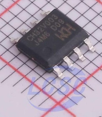
control purpose Watchdog clock ChannelSPII2CUSART Package memory No. Form I/O timer timer source No. CH32V003 F4P6 16K 2K 20 18 1 1 2 3 8 1 1 1 TSSOP20 CH32V003 F4U6 QFN20 CH32V003 A4M6 16K 2K 16 14 1 1 2 3 6 - 1 1 SOP16 CH32V003 J4M6 16K 2K 8 6 1 1 2 3 6 1 1 SOP8 CH32V003 Datasheet http://wch-ic.com Chapter
in
„HT16K33A mit CH32V003“
·
Projekte & Code
·
19.05.2025 21:12
Bild
Bild
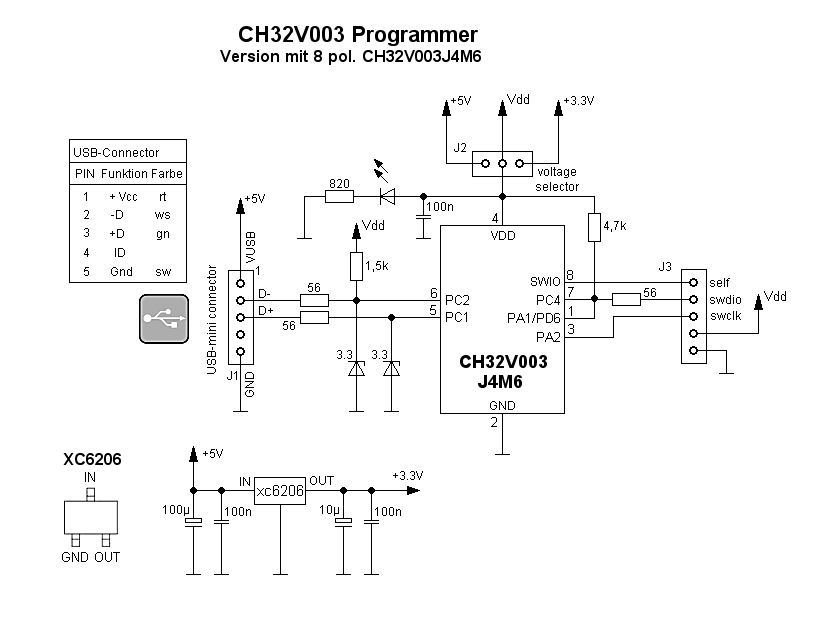
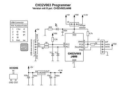
CH32V003 Programmer
Version mit 8 pol. CH32V003 J4M6
USB-Connector
PIN Funktion Farbe
1 +Vcc rt
2 -D ws
3 +D gn
4 ID
5 Gnd sw
USB+mini connector
J1
J2
voltage selector
+5V
Vdd
820
100n
4
VDD
SWIO
PC4
PA1/PD6
7
56
swdio
Vdd
PC1
5
PC2
6
3.3
3.3
J3
swclk
CH32V003 J4M6
2
GND
XC6206
IN
+5V
OUT
100µ
100n
xc6206
10µ
100n
+3.3V
in
„CH32V003-J4M6: Einfacher Rechteckgenerator 0,5 Hz 20 kHz“
·
Projekte & Code
·
09.10.2025 00:21
·
Schaltpläne
CH32FUN ) | | | +---- ch32fun.h ( dazugehoerender Header ) | | | +---- ch32fun.ld ( Linkerscript fuer CH32V003 ) | | | +---- ch32v003 hw.h ( Hardwaredeklarationen zu CH32V003 / Registeradressen ) | +---- doku | | | +---- ht16k33_b_tssop28.gif ( Schaltplan ) | | | +---- ht16k33a_4digit_7seg.pdf ( diese Dokumentation
in
„HT16K33A mit CH32V003“
·
Projekte & Code
·
15.05.2025 21:33
#include "ch32v00x.h" #include <stdint.h> #define TMP101_ADDR 0x48 // I2C-Adresse des TMP101 Sensors (Standard) #define I2C_SPEED 100000 // I2C Geschwindigkeit (100kHz) // GPIO-Pins für 7-Segment-Anzeige #define SEG_PORT GPIOA #define SEG_A GPIO_Pin_0 #define SEG_B GPIO_Pin_1 #define SEG_C GPIO_Pin_2 #define SEG_D GPIO_Pin_3 #define SEG_E GPIO_Pin_4 #define SEG_F GPIO_Pin_5 #define SEG_G GPIO_Pin_6 #define SEG_DP GPIO_Pin_7 #define DIGIT_PORT GPIOC #define DIGIT_1 GPIO_Pin_0 #define DIGIT_2 GPIO_Pin_1 #define DIGIT_3 GPIO_Pin_2 #define DIGIT_4 GPIO_Pin_3 uint8_t temp_reading = 0; uint8_t digits
in
„Copilot für MCUs“
·
Mikrocontroller und Digitale Elektronik
·
17.12.2024 13:36
.upload.maximum_data_size=2048 CH32V00x_EVT.menu.pnum.CH32V003 F4.build.mcu=QingKe-V2 CH32V00x_EVT.menu.pnum.CH32V003 F4.build.board=CH32V003 F4 CH32V00x_EVT.menu.pnum.CH32V003 F4.build.series=CH32V00x CH32V00x_EVT.menu.pnum.CH32V003 F4.build.variant=CH32V00x/CH32V003 F4 CH32V00x_EVT.menu.pnum.CH32V003 F4.build.chip=CH32V003 F4 CH32V00x_EVT.menu.pnum.CH32V003 F4.build.march=rv32ecxw CH32V00x_EVT.menu.pnum.CH32V003 F4.build.mabi=ilp32e CH32V00x_EVT.menu.pnum.CH32V003 F4.build.math_lib_gcc=-lm CH32V00x_EVT.menu.pnum.CH32V003 F4
in
„CH32V003: serieller Bootloader“
·
Projekte & Code
·
17.06.2025 07:26
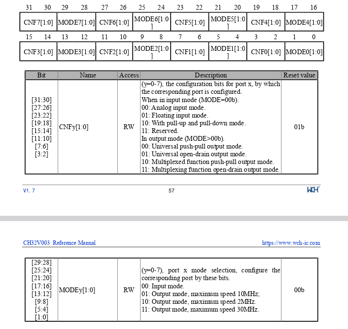
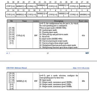
Bild
function push-pull output mode. 11: Multiplexing function open-drain output mode.
01b
V1.7 57 WCH
CH32V003 Reference Manual https://www.wch-ic.com
[29:28] [25:24] [21:20] [17:16] [13:12] [9:8] [5:4] [1:0] MODEy[1:0] RW
(y=0-7), port x mode selection, configure the corresponding port by these bits.
00:
in
„ch32v003: Diskrepanz zwischen Datenblatt und ch32v003fun“
·
Mikrocontroller und Digitale Elektronik
·
21.03.2025 12:48
·
Screenshots
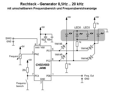
Bild
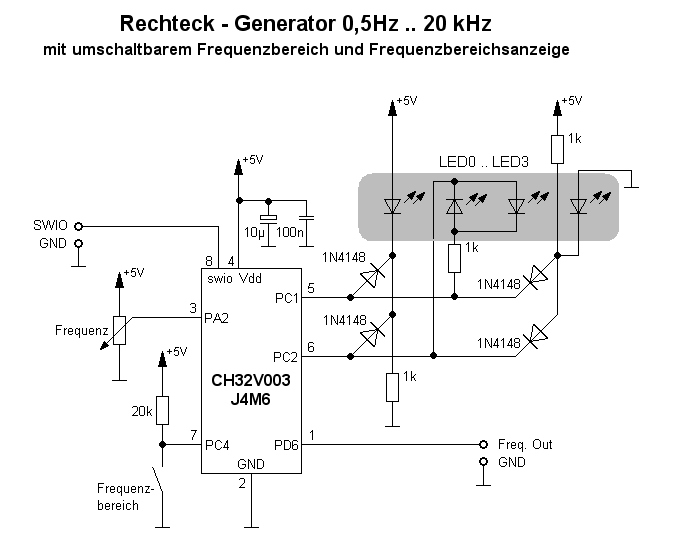
Frequenzbereichsanzeige
+5V
10µ
100n
swio
Vdd
LED0 .. LED3
1k
1N4148
1k
1N4148
1N4148
1N4148
1k
PA2
PC1
PC2
CH32V003
J4M6
PC4
PD6
20k
GND
Frequenz
Frequenzbereich
Freq. Out
GND
in
„CH32V003-J4M6: Einfacher Rechteckgenerator 0,5 Hz 20 kHz“
·
Projekte & Code
·
08.10.2025 17:00
·
Schaltpläne
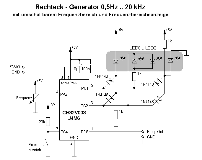
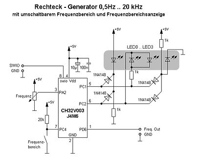
Bild
1k
LED0 .. LED3
1N4148
1k
1N4148
1N4148
1N4148
1k
+5V
10µ 100n
SWIO
GND
8 swio
4 Vdd
5 PC1
3 PA2
CH32V003
J4M6
6 PC2
7 PC4
1 PD6
2 GND
Freq. Out
GND
Frequenz
20k
Frequenzbereich
in
„CH32V003-J4M6: Einfacher Rechteckgenerator 0,5 Hz 20 kHz“
·
Projekte & Code
·
09.10.2025 05:38
·
Schaltpläne
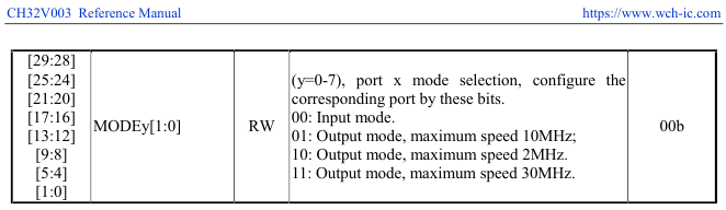
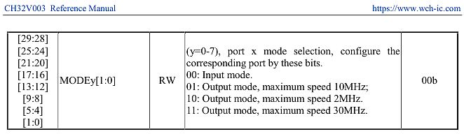
Bild
CH32V003 Reference Manual https://www.wch-ic.com
[29:28]
[25:24]
[21:20]
[17:16]
[13:12]
[9:8]
[5:4]
[1:0]
MODEy[1:0]
RW
(y=0-7), port x mode selection, configure the corresponding port by these bits.
00:
in
„Dämpfungswiderstände für TFT-SPI Display notwendig?“
·
Mikrocontroller und Digitale Elektronik
·
05.08.2025 16:30
·
Screenshots
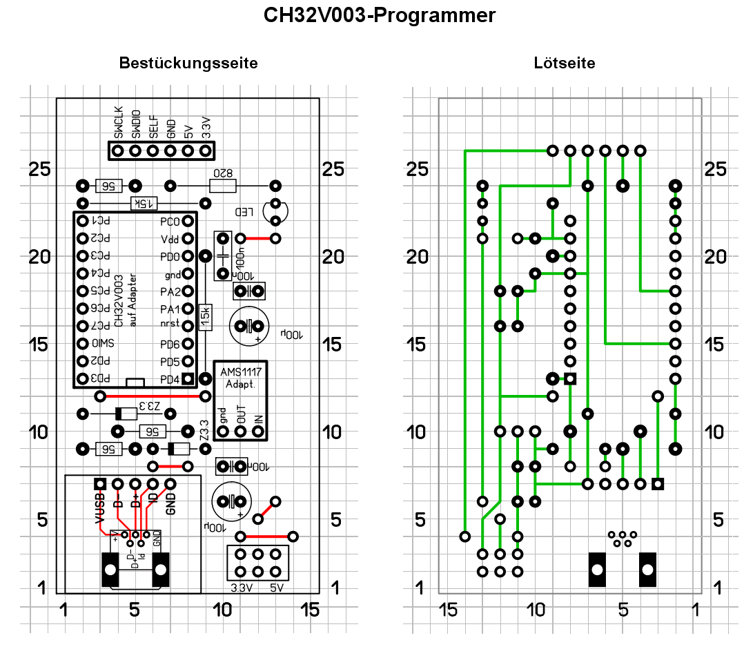
Bild
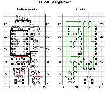
CH32V003 -Programmer Bestückungsseite Lötseite SWCLK SWDIO SELF GND 5V 33V 25 20 15 10 5 1 5 10 15 25 56 15K LED PC0 PC1 PC2 PC3 PC4 PC0 CH32V003 auf Adapter PA2 PA1 PC6 PC7 PC5 PC2 PC3 100n 15K AMS1117 Adapt
in
„CH32V003: Selbstbauprogrammer und "Getting started"“
·
Projekte & Code
·
22.05.2025 23:40
·
Layouts
PicoMon Version 3 Terminalmonitor und Frequenzzähler für CH32V003 PicoMon ist eine Firmware für CH32V003 , die umschaltbar einen seriellen Terminalmonitor sowie einen Frequenzzähler in Verbindung mit einem farbigen SPI Display darstellt. Das Terminalprogramm Das
in
„PicoMon für CH32V003 oder STM32F0xx“
·
Projekte & Code
·
05.10.2025 21:57
Bild
CH32V003 All Images Videos News Maps Shopping
Germany
Shopping for CH32V003
CH32V003
INDUSTRIAL-GRADE MCU
RISC-V2A
SINGLE-WIRE SERIAL DEBUG INTERFACE
SYSTEM FREQUENCY 48MHZ
50Pcs Ch32v003 Mikro Controller
in
„Uhr mit STM8Sxx3 und TM1637“
·
Projekte & Code
·
23.01.2025 10:04
·
Screenshots
Bild
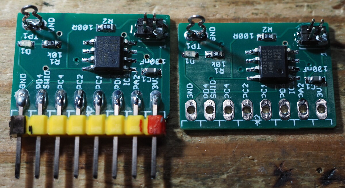
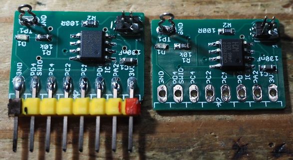
TP1, GND, R2, 100R, D1, R1, 10K, IC, CH32X003, JAM6 D03, 130nF, PC4, PC2, PC1, PD4, PD0, SWIO, CA2, GND, 3U, PC2, PC1, PD4, SWIO, GND
in
„CH32V003 Minimales Testboard“
·
Projekte & Code
·
14.04.2024 08:59
·
Platinenfotos
Bild
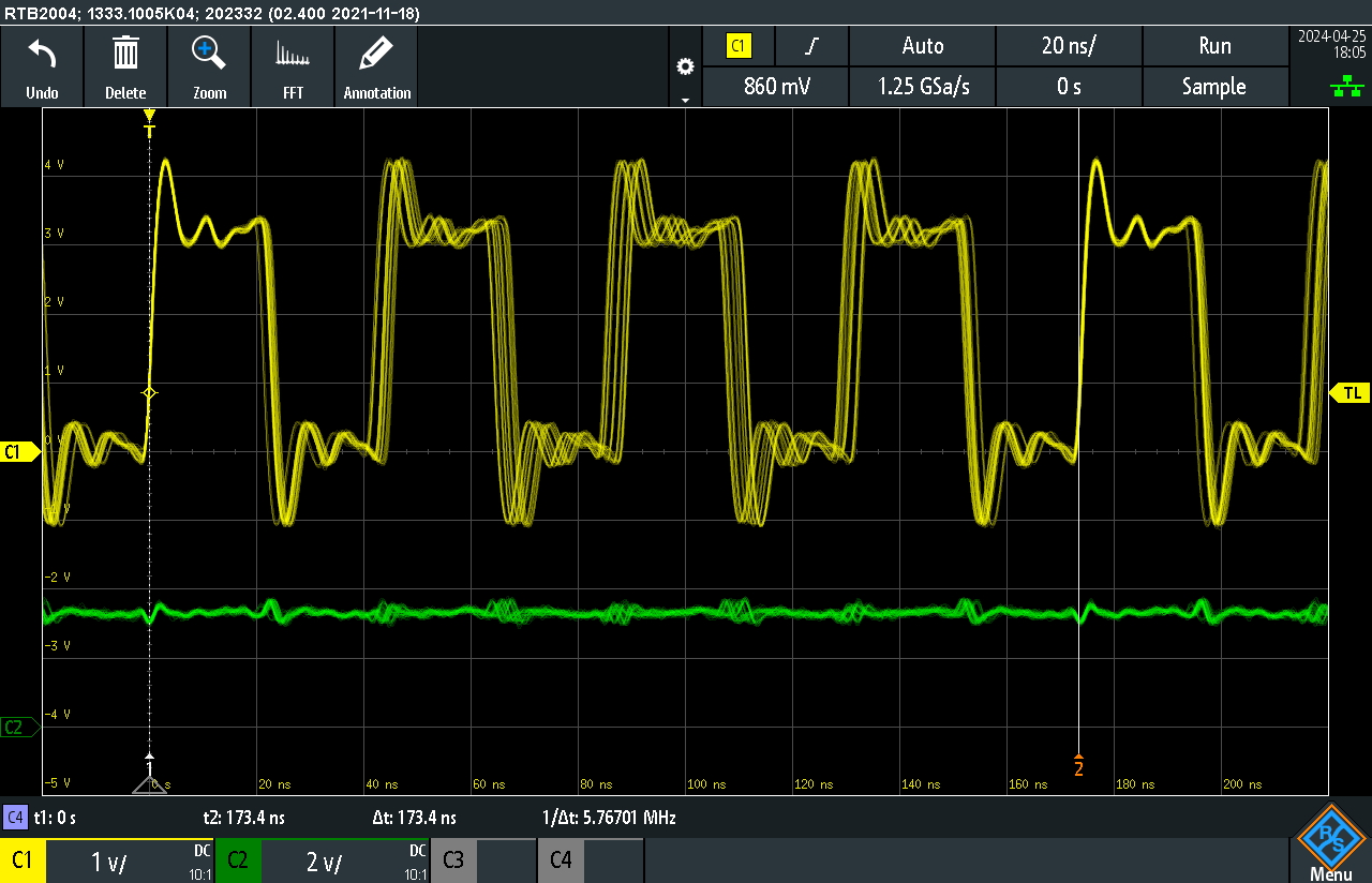
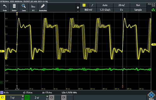
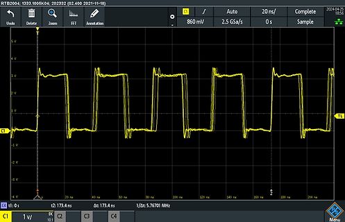
RTB2004: 1333.1005K04: 202332 (02.400 2021-11-18) 2024-05-25 18:05 Undo Delete Zoom FFT Annotation Auto 20 ns/ Run Sample 4 V 2 V V -2 V -3 V -4 V -5 V C1 860 mV 1.25 GSa/s 0 s C2 2 v/ DC 10:1 C3 1/Δ: 5.76701 MHz C4 t1: 0 s t2: 173.4 ns Δt: 173.4 ns 160 ns 180 ns 200 ns TL C1 1 v/
in
„CH32V003 RC-Oscillator / Jitter“
·
Analoge Elektronik und Schaltungstechnik
·
25.04.2024 19:24
·
Oszi-Bilder
Bild
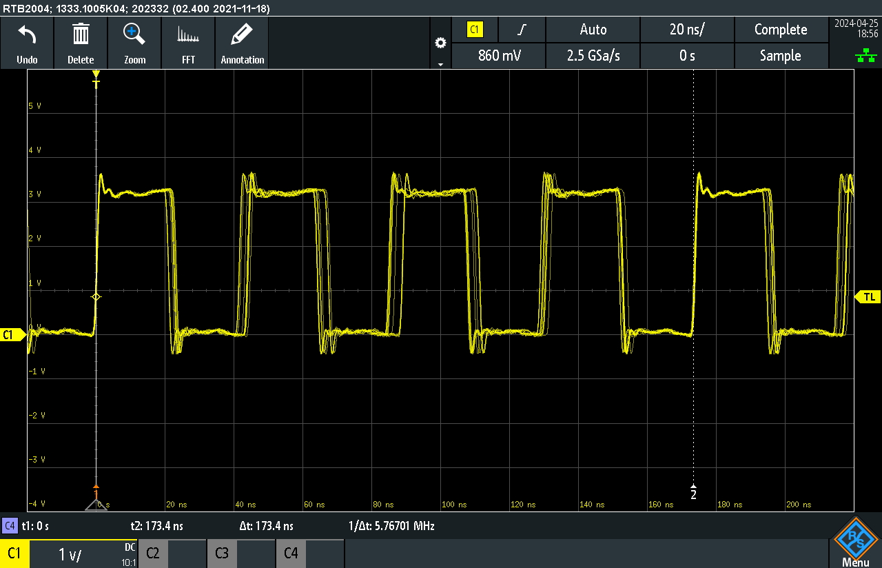
RTB2004: 1333.1005K04; 202332 (02.400 2021-11-18; 2024-05-25 18:56; Undo; Delete; Zoom; FFT; Annotation; Auto; 20 ns/; Complete; 860 mV; 2.5 GSa/s; 0 s; Sample; 5 V; 4 V; 3 V; 2 V; 1 V; C1; TL; 0 V; -1 V; -2 V; -3 V; -4 V; 20 ns; 40 ns; 60 ns; 80 ns; 100 ns; 120 ns; 140 ns; 160 ns; 180 ns; 200 ns; t2: 173.4 ns; Δt: 173.4 ns; 1/Δt: 5.76701 MHz; C4 t1: 0 s; C1 1 v/; 10:1; C2; C3; C4; Menu
in
„CH32V003 RC-Oscillator / Jitter“
·
Analoge Elektronik und Schaltungstechnik
·
25.04.2024 20:07
·
Oszi-Bilder
Bild
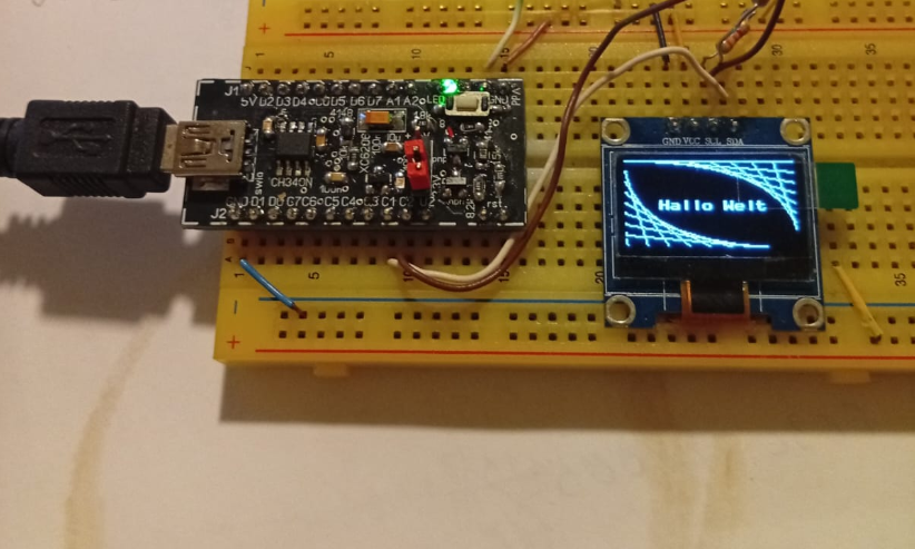
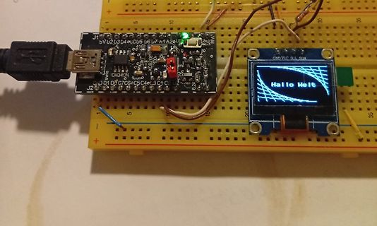
J1 5V D2 D3 D4 C0 U5 U6 D7 A1 A2 LED CH340N J2 GND VCC SCL SDA Hallo Welt
in
„CH32V003-J4M6: Einfacher Rechteckgenerator 0,5 Hz 20 kHz“
·
Projekte & Code
·
09.10.2025 20:45
·
Fotos
Bild
Bild
Verwendung eines HT16K33 LED-Treibers mit I2C- Interface. Hier fuer Anschluss mit max. 8-Digits MCU : CH32V003 Takt : 13.05.2025 R. Seelig ------------------------------------------------------------------ */ /* CH32V003 A4M6 CH32V003 F4P6 +-----------+ +--------------+ PC1 / sda |1 C 16| PC0 PD4 / a7 | 1 20
in
„HT16K33A mit CH32V003“
·
Projekte & Code
·
15.05.2025 21:33
festzustellen, wie schnell ein Apfelmaennchen berechnet werden kann Hinweis: Funktioniert nur mit CH32V003 F4P6, da die Chips in den 8 und 16 poligen Gehaeusen keinen SPI-SCK Anschluss nach aussen gefuehrt haben. MCU : CH32V003 Takt : 13.04.2025 R. Seelig ------------------------------------------------
in
„CH32V003, float wirklich langsam?“
·
Mikrocontroller und Digitale Elektronik
·
15.04.2025 23:24
Bild
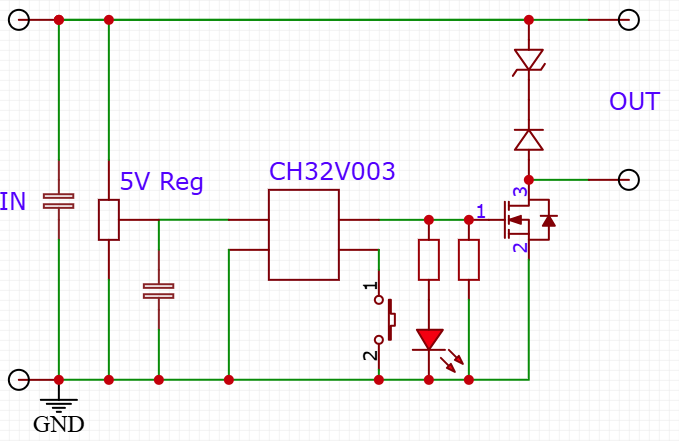
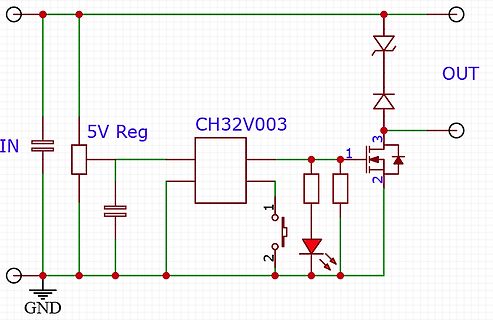
5V Reg CH32V003 OUT IN GND 1 2 3
in
„Elektronische Türöffner mit DC zum Summen bringen“
·
Haus & Smart Home
·
28.09.2025 14:05
·
Schaltpläne
Bild
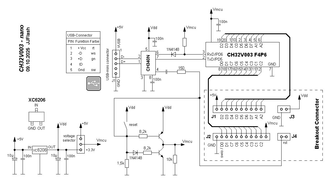
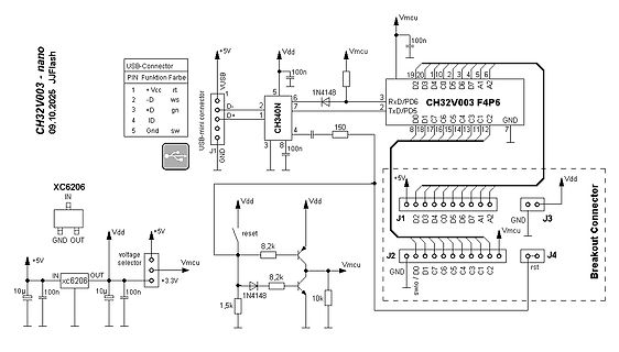
CH32V003 - nano JJFlash 09.10.2025 USB-Connector PIN Funktion Farbe 1 +Vcc rt 2 -D ws 3 +D gn 4 ID 5 Gnd sw J1 USB-mini connector VUSB D- 1 2 D+ CH340N 16 7 3 RxD/PD6 CH32V003 F4P6 19 20 1 2 3 4 5 6 TxD/PD5
in
„CH32V003-J4M6: Einfacher Rechteckgenerator 0,5 Hz 20 kHz“
·
Projekte & Code
·
09.10.2025 20:39
·
Schaltpläne
Bild
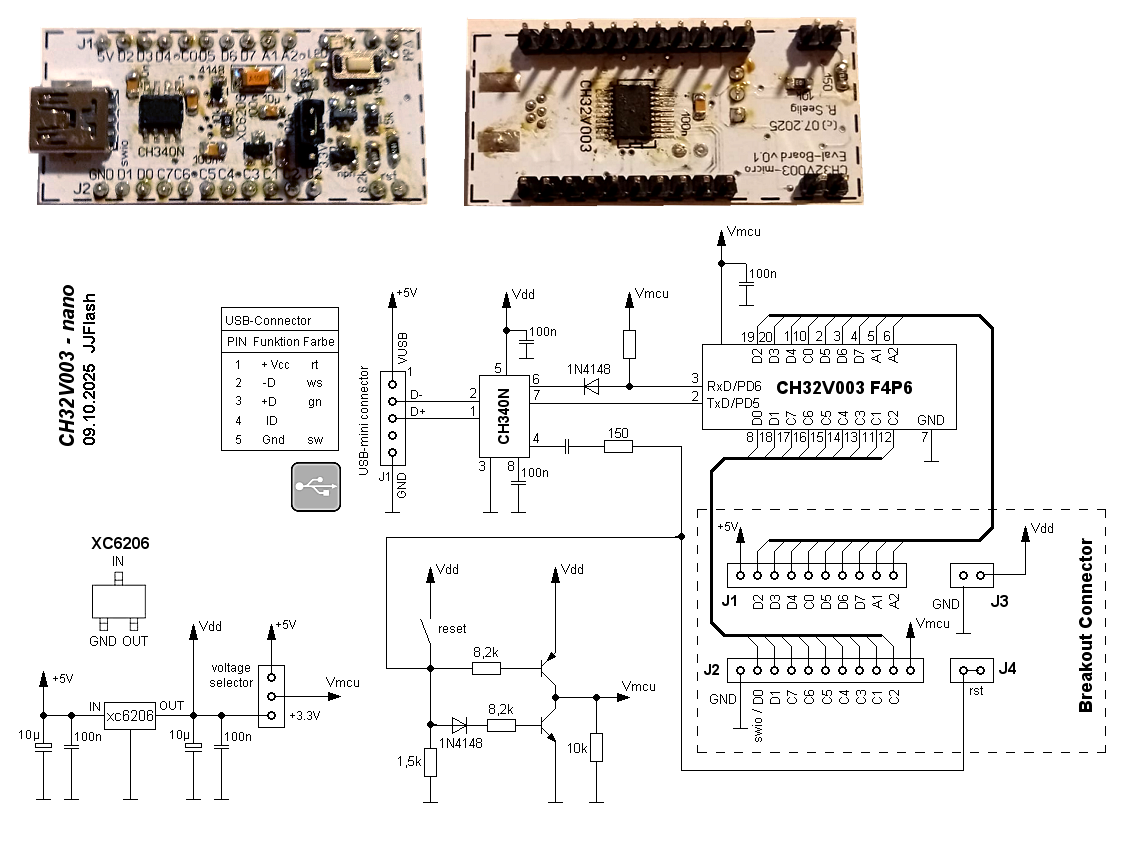
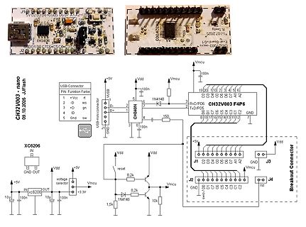
CH32V003 - nano 09.10.2025 JJFlash USB-Connector PIN Funktion Farbe +Vcc rt D ws D gn GND sw J1 GND 01 00 C7C6 C5 C4 C3 C1 CH340N D+ 1 2 3 4 5 6 7 8 100n Vdd Vmcu 1N4148 RxD/PD5 TxD/PD5 GND CH32V003 F4P6 Breakout
in
„CH32V003 und Arduino“
·
Mikrocontroller und Digitale Elektronik
·
03.03.2026 21:01
·
Schaltpläne
PicoMon Terminalmonitor für CH32V003 und STM32F0xx Mikrocontroller PicoMon ist eine Firmware für CH32V003 und STM32F0xx, die in Verbindung mit farbigen TFT-Displays und SPI-Interface einen Terminalmonitor darstellt. PicoMon stellt die
in
„PicoMon für CH32V003 oder STM32F0xx“
·
Projekte & Code
·
22.04.2025 19:41
Bild
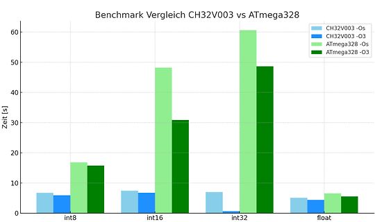
Benchmark Vergleich CH32V003 vs ATmega328
CH32V003 -Os
CH32V003 -O3
ATmega328 -Os
ATmega328 -O3
Zeit [s]
int8
int16
int32
float
in
„CH32V003, float wirklich langsam?“
·
Mikrocontroller und Digitale Elektronik
·
21.11.2025 01:36
·
Diagramme
Bild
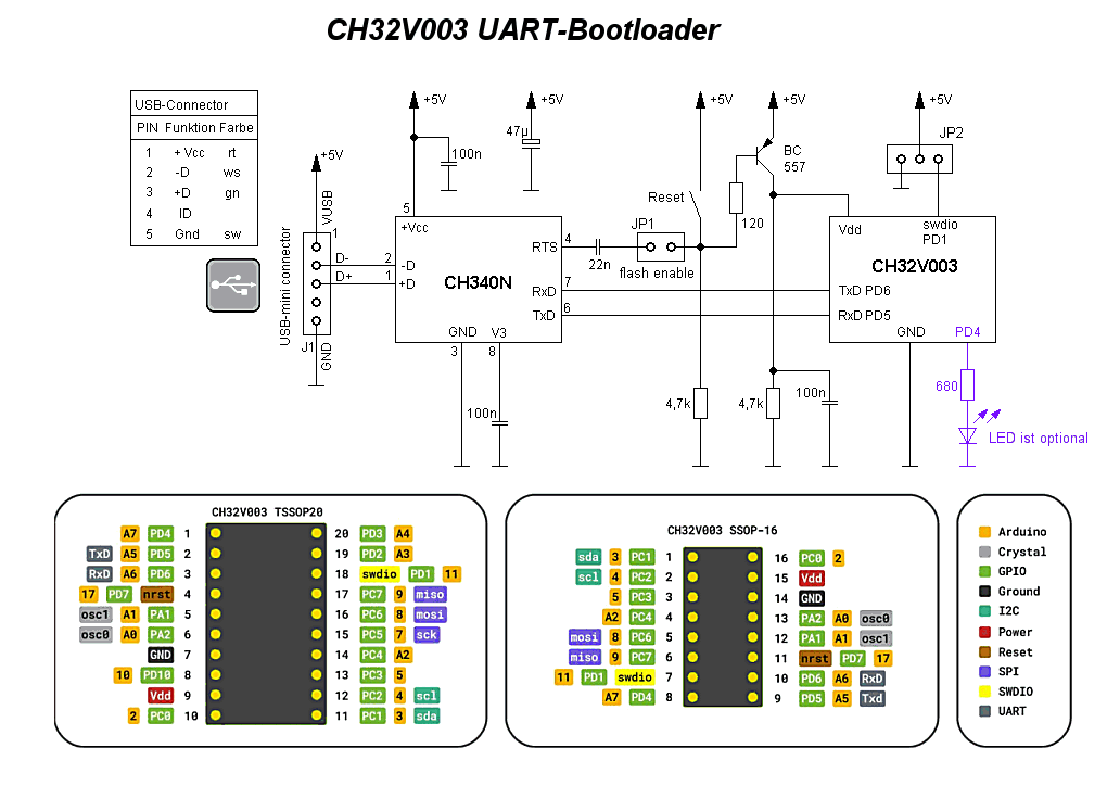
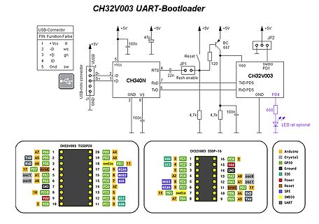
CH32V003 UART-Bootloader
USB-Connector
+Vcc rt
-D ws
+D gn
ID
Gnd sw
J1
CH340N
+5V
100n
47u
JP1
Reset
120
BC 557
swdio PD1
Vdd
TxD PD6
RxD PD5
swdio
flash enable
4,7k
4,7k
100n
680
LED ist optional
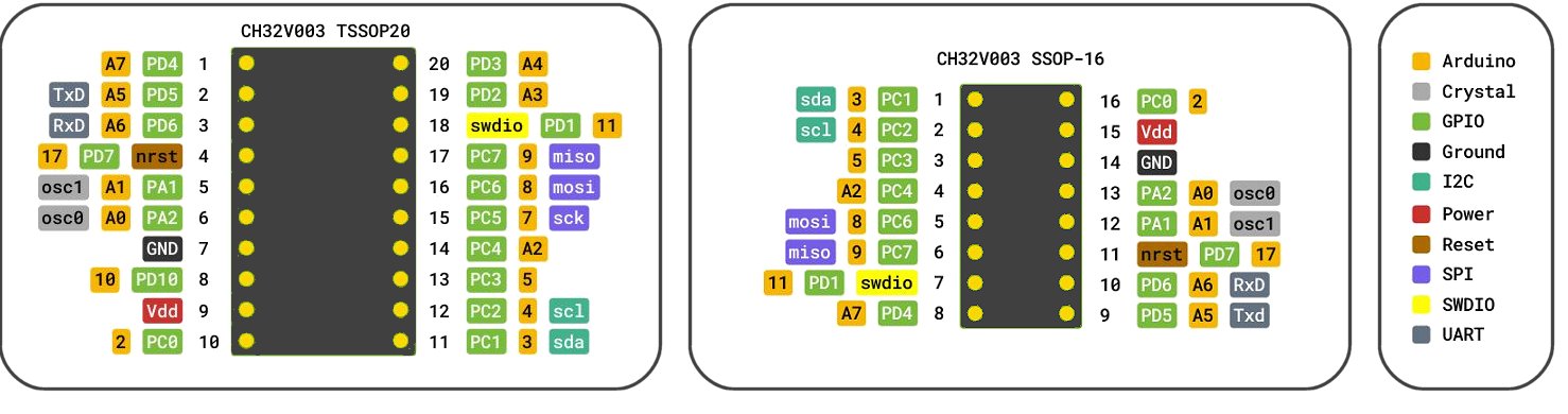
CH32V003 TSSOP20
CH32V003 SSOP-16
Arduino
Crystal
GPIO
Ground
I2C
Power
Reset
SPI
SWDIO
UART
in
„CH32V003: serieller Bootloader“
·
Projekte & Code
·
09.06.2025 13:43
·
Schaltpläne
MineSweeper fuer CH32V003 ----------------------------------------------- Das Vorliegende Projekt ist ein "Makefile"-Projekt ohne IDE unter Linux! Ein systemweit verfuegbarer Compiler sowie das Flashingtool minichlink wird
in
„MineSweeper für CH32V003 (Linux Makefile-Projekt)“
·
Projekte & Code
·
25.08.2025 23:39
gewohnte Funktionen wie print und println ebenfalls verfügbar. extendedSerial wurde auf AVR-, STM- und CH32V003 Systemen getestet. Anmerkung zu CH32V003 : Der Arduino-Core von CH32V003 ist in einigen Teilen noch fehlerbehaftet und im Falle von HardwareSerial sind nicht alle Funktionen komplett implementiert.
in
„Arduino und struct gefallen sich nicht !“
·
Mikrocontroller und Digitale Elektronik
·
23.03.2026 20:09
Bild
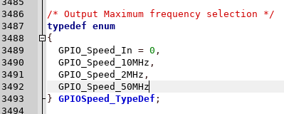
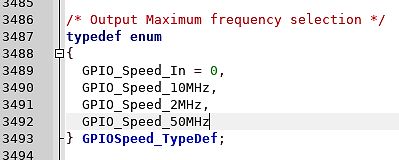
/* Output Maximum frequency selection */
typedef enum
{
GPIO_Speed_In = 0,
GPIO_Speed_10MHz,
GPIO_Speed_2MHz,
GPIO_Speed_50MHz
} GPIOSpeed_TypeDef;
in
„ch32v003: Diskrepanz zwischen Datenblatt und ch32v003fun“
·
Mikrocontroller und Digitale Elektronik
·
21.03.2025 12:48
·
Screenshots
Bild
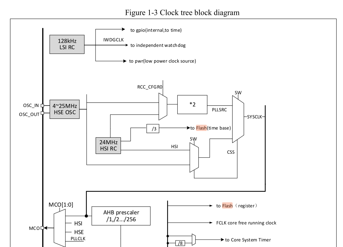
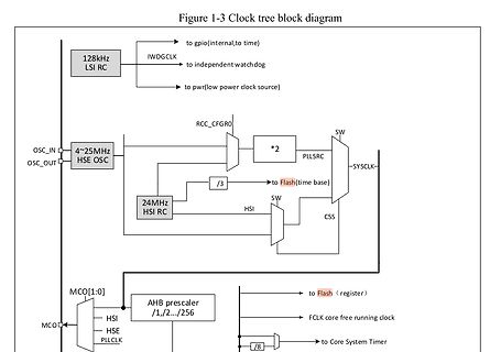
Figure 1-3 Clock tree block diagram
to gpio(internal,to time)
128kHz LSI RC
IWDGCLK
to independent watch dog
to pwr(low power clock source)
OSC_IN
OSC_OUT
4~25MHz HSE OSC
RCC_CFGR0
*2
SW
PLLSRC
SYSCLK
/3
to Flash(time base)
24MHz HSI RC
SW
HSI
CSS
MCO[1:0]
AHB prescaler
/1,/2.../256
HSI
FCLK core running clock
MCO
HSE CLK
to Flash (register)
/8
to Core System Timer
in
„RISCV (CH32V003): GNU Assembler übersetzt "CALL" nicht korrekt (oder bin ich nur zu doof?)“
·
Mikrocontroller und Digitale Elektronik
·
03.07.2025 08:14
·
Diagramme
SRAM_start = 0x20000000 SRAM_end = 0x20000800 STACK = 0x20000800 TIM2_BASE = 0x40000000 W_WDG_BASE = 0x40002C00 I_WDG_BASE = 0x40003000 I2C_BASE = 0x40005400 PWR_BASE = 0x40007000 AFIO_BASE = 0x40010000 EXTI_BASE = 0x40010400 PORTA_BASE = 0x40010800 PORTC_BASE = 0x40011000 PORTD_BASE = 0x40011400 ADC_BASE = 0x40012400 TIM1_BASE = 0x40012C00 SPI_BASE = 0x40013000 USART_BASE = 0x40013800 DMA_BASE = 0x40020000 RCC_BASE = 0x40021000 FLASH_INTERFACE_BASE = 0x40022000 EXTENDED_MEM_BASE = 0x40023800 CORE_PRIVATE_BASE = 0xE0000000 FLASH_BASE = 0x08000000 R32_PWR_CTLR = 0x40007000 #Power control register R32
in
„RISCV (CH32V003): GNU Assembler übersetzt "CALL" nicht korrekt (oder bin ich nur zu doof?)“
·
Mikrocontroller und Digitale Elektronik
·
29.06.2025 15:08
rechteck_j4m6.c Einfacher Rechteckgenerator mit 4 mittels einem Taster umschaltbaren Frequenzbereich MCU : CH32V003 J4M6 (8 pol.) 08.10.2025 R. Seelig -------------------------------------------------------- */ /* CH32V003 J4M6 +---------+ PD6 / A6 / urx / T2CH3_/ utx_ | 1 8 | PD4 / A7 / UCK / T2CH1ETR PA1 / osc1
in
„CH32V003-J4M6: Einfacher Rechteckgenerator 0,5 Hz 20 kHz“
·
Projekte & Code
·
08.10.2025 17:01
------------------------------------ v003_uart.h Header fuer rudimentaere UART-Funktionen MCU : CH32V003 Takt : 48 MHz 30.11.2025 R. Seelig ------------------------------------------------------ */ /* CH32V003 A4M6 CH32V003 F4P6 +-----------+ +--------------+ PC1 / sda |1 C 16| PC0 PD4 / a7 | 1 20 | PD3
in
„Arduino und CH32V003“
·
Mikrocontroller und Digitale Elektronik
·
30.11.2025 01:14
Bild
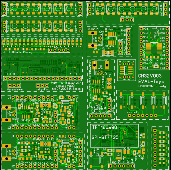
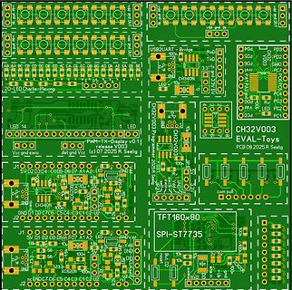
GND 3.3V LED 10u CH340N PC5 PC4 PC3 PC2 PC1 PA1 PA2 PD4 PD3 PD2 PD0 LED 20-LED Charlie-Plexing CH32V003 Programer 08.2025 R Seelig EVAL-Toys PCB SPI-ST7735 TFT160x80 5V D2 D3 D4 D5 D6 D7 A1 A2 LED GND Vdd 100n 10u 47 10k 1k 47 100n 10u 47 10k 1k 47 100n 10u 47 10k 1k 47 100n 10u 47 10k 1k 47 100n 10u
in
„CH32V003-J4M6: Einfacher Rechteckgenerator 0,5 Hz 20 kHz“
·
Projekte & Code
·
09.10.2025 00:22
·
Layouts
Bild
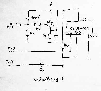
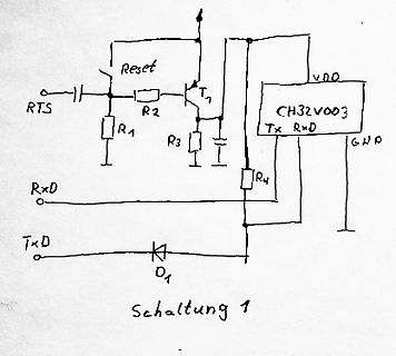
Reset RTS R1 R2 T1 R3 RxD TxD VDD CH32V003 GND R4 D1 Schaltung 1
in
„Einschalten der Mikrocontroller-Betriebsspannung“
·
Mikrocontroller und Digitale Elektronik
·
17.06.2025 23:27
·
Schaltpläne
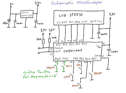
Bild
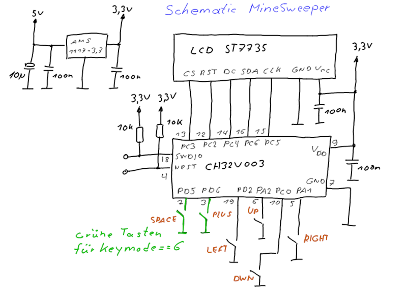
ST7735
CS RST DC SDA CLK GND Vcc
3,3V
3,3V
10k
10k
13 12 14 16 15
PC3 PC2 PC4 PC6 PC5
18 SWDIO
CH32V003
4 NRST
VDD
9
100n
GND 7
PD5 PD6 PD2 PA2 PC0 PA1
2 3 19 5 0 1
SPACE PLUS UP RIGHT
LEFT DWN
grüne Tasten für keymode=6
in
„MineSweeper für CH32V003 (Linux Makefile-Projekt)“
·
Projekte & Code
·
25.08.2025 23:39
·
Schaltpläne
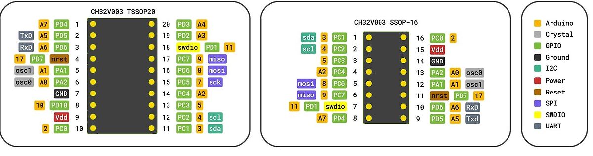
Bild
CH32V003 TSSOP20 PD3 A4 PD2 A3 swdio PD1 PD10 A7 PD7 nrst PA1 PC7 miso PC6 mosi PC8 sck PC5 PC4 A2 PC3 PC2 scl PC1 sda PD5 A5 PD4 A7 PD6 A6 RxD PD10 A1 PA1 PD5 A5 PD4 A7 PD6 A6 RxD PD10 A1 PA1 PD5 A5 PD4 A7
in
„CH32V003: Selbstbauprogrammer und "Getting started"“
·
Projekte & Code
·
22.05.2025 23:44
·
Diagramme
----------------------------------------------------- uart_bootload.c Serieller Bootloader fuer CH32V003 Mikrocontroller Anmerkungen zum Flashspeicher: Es ist keine einfache Schreibmoeglichkeit gegeben, ein ueberschreiben eines Bytes ist nicht moeglich, es muss zuvor geloescht sein. Da der Flashspeicher
in
„CH32V003: serieller Bootloader“
·
Projekte & Code
·
09.06.2025 13:45
/* ------------------------------------------------------- benchmark2_portable.c MCU : CH32V003 Takt : 48 MHz 21.11.2025 R. Seelig ------------------------------------------------------- */ #include <stdint.h> #include <stdlib.h> #include <stdarg.h> #include <string.h> #include "ch32fun.h" #include "ch32v003 _gpio.h" #include "systick.h" #include "my_printf.h" #include "uart.h" #define printf my_printf #define baud 115200 volatile uint32_t bench_checksum = 0; uint32_t prog_millis8; uint32_t prog_millis16
in
„CH32V003, float wirklich langsam?“
·
Mikrocontroller und Digitale Elektronik
·
21.11.2025 01:04
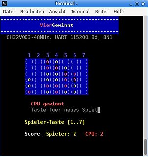
Bild
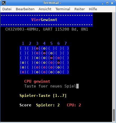
Terminal -
Datei Bearbeiten Ansicht Terminal Reiter Hilfe
VierGewinnt
CH32V003 -48MHz, UART 115200 Bd, 8N1
1 2 3 4 5 6 7
CPU gewinnt
Taste fuer neues Spiel
Spieler-Taste [1..7]
Score Spieler: 2 CPU: 2
in
„Vier Gewinnt für CH32V003 und Linux-Toolchain“
·
Projekte & Code
·
05.05.2025 18:22
·
Screenshots
Bild
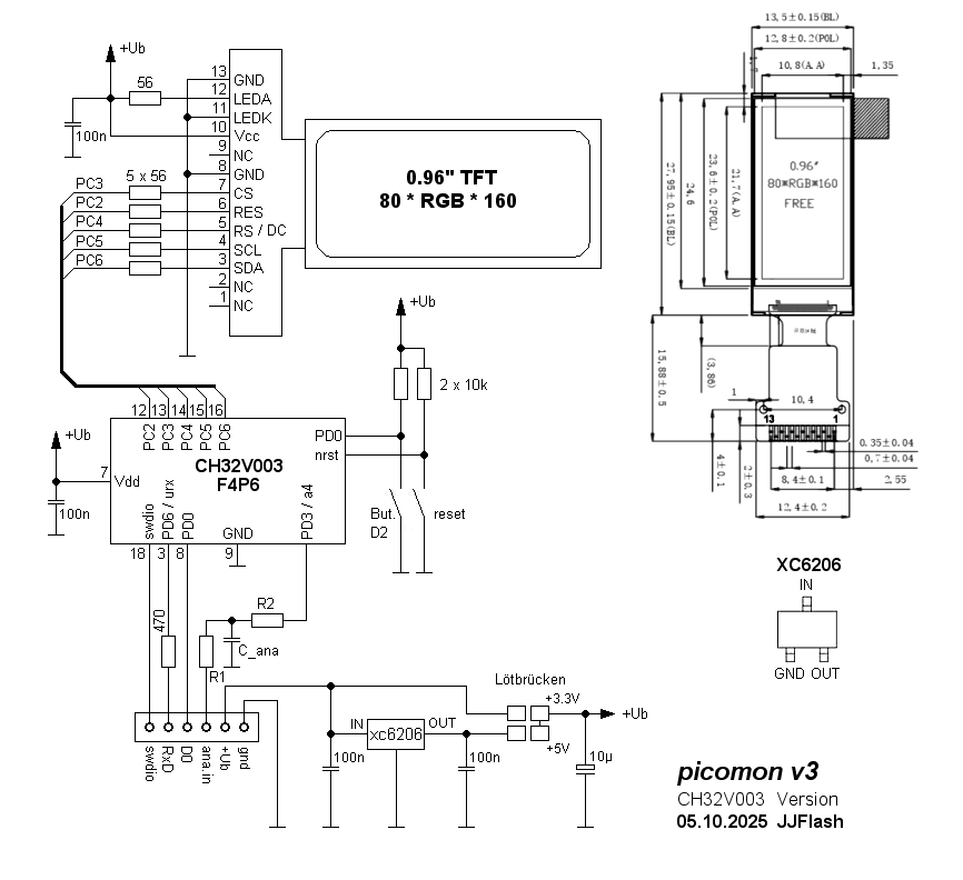
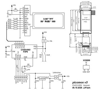
CS 6 RES 5 RS/DC 4 SCL 3 SDA 2 NC 1 NC 56 100n +Ub 2 x 10k PD0 / urx PC2 PC3 PC4 PC5 7 Vdd 100n CH32V003 F4P6 nrst PD3 / a4 But D2 reset 18 3 8 470 swdio PD0 GND 9 R2 R1 C_ana swdio RXD D0 +ub ana_in gnd xc6206 IN OUT 100n 100n +3.3V +Ub +5V 10u GND OUT picomon v3 CH32V003 Version 05.10.2025 JJFlash
in
„PicoMon für CH32V003 oder STM32F0xx“
·
Projekte & Code
·
05.10.2025 21:57
·
Schaltpläne
Bild
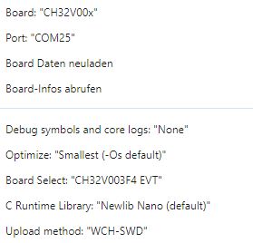
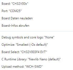
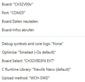
Board-Infos abrufen
Debug symbols and core logs: "None"
Optimize: "Smallest (-Os default)"
Board Select: "CH32V003 F4 EVT"
C Runtime Library: "Newlib Nano (default)"
Upload method: "WCH-SWD"
in
„CH32V003 will sich nicht programmieren lassen“
·
Mikrocontroller und Digitale Elektronik
·
21.07.2025 19:53
·
Screenshots
Bild
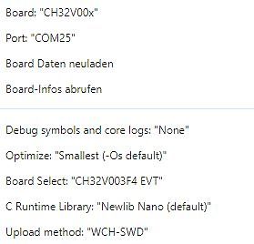
Board-Infos abrufen
Debug symbols and core logs: "None"
Optimize: "Smallest (-Os default)"
Board Select: "CH32V003 F4 EVT"
C Runtime Library: "Newlib Nano (default)"
Upload method: "WCH-SWD"
in
„CH32V003 will sich nicht programmieren lassen“
·
Mikrocontroller und Digitale Elektronik
·
21.07.2025 19:55
·
Screenshots
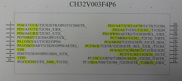
Bild
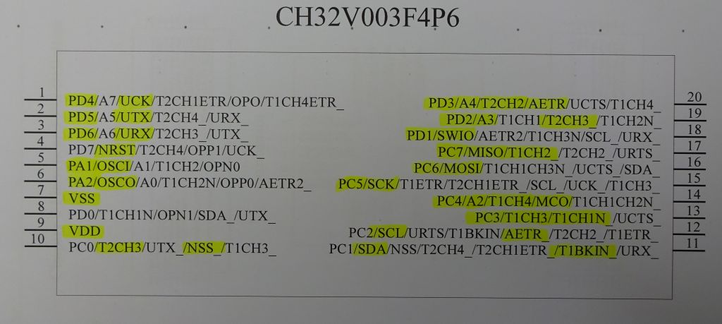
CH32V003 F4P6
1 PD4/A7/UCK/T2CH1ETR/OPO/T1CH4ETR_
2 PD5/A5/UTX/T2CH4_/URX_
3 PD6/A6/URX/T2CH3_/UTX_
4 PD7/NRST/T2CH4/OPP1/UCK_
5 PA1/OSCI/A1/T1CH2/OPN0
6 PA2/OSCO/A0/T1CH2N/OPP0/AETR2_
7 VSS
8 PD0/T1CH1N/OPN1
in
„CH32V003 - Experimente mit dem Zehn Cent-Mikrocontroller“
·
Mikrocontroller und Digitale Elektronik
·
25.07.2023 19:11
·
Screenshots

 Bild
Bild
 Bild
Bild
 Bild
Bild
 Bild
Bild
 Bild
Bild
 Bild
Bild
 Bild
Bild
 Bild
Bild
 Bild
Bild
 Bild
Bild
 Bild
Bild
 Bild
Bild
 Bild
Bild
 Bild
Bild
 Bild
Bild
 Bild
Bild
 Bild
Bild
 Bild
Bild
 Bild
Bild
 Bild
Bild
 Bild
Bild
 Bild
Bild
 Bild
Bild
 Bild
Bild
 Bild
Bild
 Bild
Bild
 Bild
Bild
 Bild
Bild
 Bild
Bild
 Bild
Bild