1.0.0 [ 59.170] ABI class: X.Org Server Extension, version 10.0 [ 59.170] (==) Matched ati as autoconfigured driver 0 [ 59.170] (==) Matched modesetting as autoconfigured driver 1 [ 59.170] (==) Matched fbdev as autoconfigured driver 2 [ 59.170] (==) Matched vesa as autoconfigured
, ATI Radeon HD 2600 Pro, ATI Gemini RV630, ATI Gemini Mobility Radeon HD 2600 XT, ATI FireGL V5600, ATI FireGL V3600, ATI Radeon HD 2600 LE, ATI Mobility FireGL Graphics Processor, ATI Radeon HD 3470, ATI Mobility Radeon HD 3430, ATI Mobility Radeon HD 3400 Series, ATI Radeon HD 3450,
dynamic power algorithm across 1024 nodes. Z-Wave SDK 8.0: Intelligent Network Behavior Under Load As networks grow, static assumptions begin to limit performance. SDK 8.0 introduces a more intelligent approach to throughput management, with network-composition-aware dynamic speed selection that improves
affected, including our public APIs and Device Hub. This may impact device activation, device management, as well as OS and application updates. [/c] ### Tindie: Stellungnahme der neuen Eigentümer Die „Aufregung“ um die Offlinenahme von Tindie führte nun zu einer Reaktion. Die neuen Käufer schickten
convertor. ; _ This impedance matching also applies to the input of the trigger level comparator, as otherwise itwould draw current from the signal. 15 1.3.4.3, Active filter A Filters placed in feedback loops around an amplifier stage are referred to as active filters.They have sharper transition between
regulation accuracy, the BQ2057 uses the feedback on the BAT pin. Externally, this pin should be connected as close to the battery cell terminals as possible. For additional safety, a 10-kΩ internal pullup resistor is connected between the VSENSE and OUT pins. 12.1.4 Enable (TS) The TS pin can be used as charge-inhibit
Beitrag #8020687: > langsam drehende (<100 U/min) Motore. Getriebemotore mit On-Axis Encoder. Siehe AS5600 Ich würde wohl der Einfachheit halber bei DC Bürstenmotor mit H-Brücke und PWM bleiben. Ein Referenz Motor bei fester Drehzahl und der andere wird geregelt. Schrittmotor ist Overkill und bringt
microcontroller to Wiring. Then they forked (or copied) the Wiring source code and started running it as a separate project, called Arduino. [/code] https://arduinohistory.github.io/#the-formation-of-arduino
Dinge mit einbindet, dass der Speicherbedarf bei Verwendung dieser delayMicroseconds um mehr als 5600 Byte angestiegen ist (was bei einem gesamten Flashspeicher von 16 kByte enorm ist). Also gibt es bei mir, wenn es genauer sein soll, hier eine Verzögerung, die mittels Timer2 realisiert wird und
the operation, the housing becomes very hot. Do not switch the device on and off in short intervals as this would reduce the lamp’s life. 18/55 00020552.DOC, Version 1.5 HEALTH!HAZARD! Never!look!directly!into!the!light!source,!as!sensitive!persons!may!suffer!an epileptic!shock!(especially!meant!for!epileptics
Fig.4 Overall signal gain as a function of feedback resistors R2 and R3 (R1 = 150 k ). Fig.5 Stereo blend characteristic (SNC). 1996 Sep 02 9 Philips Semiconductors Product specification PLL stereo decoder and noise blanker TDA1591
abnormality which has occurred previously can be defined moment when the protection function worked as long as the backup data has been stored. (Reference voltage: 3.3 V=255) For details, refer to“T4. PROTECTIONDETECTION” menu. TMP1: Heatsink TMP3: Bridge diode 2-3. 電源部の電圧異常によりプロテクションが働いた 原因: 2-6. スピーカー
optical instruments with this product will increase eye hazard. Repair handling should take place as much as possible with a disc loaded inside the player WARNING LOCATION: INSIDE ON LASER COVERSHIELD CAUTION VISIBLE AND INVISIBLE LASER RADIATION WHEN OPEN AVOID EXPOSURE TO BEAM ADVARSEL SYNLIG OG USYNLIG
is LOW. // Define input PB1 #define PB1 1 // Define output PB0 #define PB0 0 // Set PB1 as input with internal pullup pinMode(PB1, INPUT_PULLUP); // Set PB0 as output pinMode(PB0, OUTPUT); // Check if input is LOW if(digitalRead(PB1) == LOW) { // Activate buzzer on output tone
Aber es kann auch anders kommen. Zu Deiner Ausgabefrequenz: [pre] (2800µs EIN + 2800µs AUS) = 5600µs Periodendauer [/pre] Frequenz wäre demnach: [pre] 1 / 5600E-6 = 178.5 Hertz [/pre] weit weg von 3200 Hz Dauer des Tones: [pre] (2800µs EIN + 2800µs AUS) * 10 = 0.056 = 56ms [/pre] Zu
und den 12V Lüfter (über 5 x 1N4001 in Reihe..). ich denk auch die ganzen Elkos 10Elkos (63V / 5600µF) machen keine Sinn, 6 davon hängen direkt auf der 24V Spannung, 2 nach dem 15V Regler, die andern 3 sind so ein "Puffer" zwischen 24V Batteriespannung und der Versorgung des 15V Reglers, wischen
eine Axt nicht. Die Spannung wird unterbrochen. "The name is derived from having the same effect as throwing a crowbar over exposed power supply terminals to short the output."
Ich habe mich bei der Bestellung der Sensoren für ein Projekt verschaut und versehentlich AS5600 anstatt AS5600L gekauft. Das bedeutet ich habe etliche Sensoren die alle mit der selben unveränderlichen Adresse am I2C Bus hängen. Klar könnte ich einen Busmultiplexer verwenden oder die richtigen
macht der AS5600 nicht und als Master kann er auch nicht agieren. Barny F. schrieb im Beitrag #7909999: > Das bedeutet ich habe etliche Sensoren die alle mit der selben > unveränderlichen Adresse am I2C Bus
ganze lowcost , da ich 15schalter habe Sehr preisgünstig sind magnetische Encoder auf der Basis des AS5600 oder MT6701. Beim Chinesen bekommst du die benötigten 15 Stück als fertige Module für weniger als 20 € (alle zusammen). Diese Encoder haben 12 oder 14 Bit Auslösung. Um auf die 35 Schritte zu
lowcost , da ich 15schalter habe > > Sehr preisgünstig sind magnetische Encoder auf der Basis des AS5600 oder > MT6701. Beim Chinesen bekommst du die benötigten 15 Stück als fertige > Module für weniger als 20 € (alle zusammen). > > Diese Encoder haben 12 oder 14 Bit Auslösung. Um auf die 35 Schritte
Backup-Medium zugelegt, einen CD2600. Der lief tatsächlich jahrelang... Ich habe hier noch eine HP J-5600 stehen, Baujahr ca. 2000. Mit 4 15000er SAS Platten (je 146 GB). Die funktioniert immer noch 1a und die Platten ebenfalls. Allerdings nutze ich die aus Gründen der Energieeffizienz heute nicht mehr
~/SMART# fgrep "Model" smart.2.txt Model Family: Seagate Archive HDD Device Model: ST8000AS0002-1NA17Z [/pre] Von den 6 Platten im RAID sind noch 2 Original (#5 und #8): [pre] root@zeta3:~/SMART# fgrep "Model" smart.5.txt Model Family: Western Digital Red Device Model: WDC WD60EFRX
musical data are stored in the 512 Mbit Nand Flash IC81 TC58DVM92A1TG00BBH. The Nand flash is treated as a virtual drive by means of a Disk Operative System. Before using it, it has to be formatted as a normal drive. The formatting also creates a directory needed for the functioning of the G-70. The data
musical data are stored in the 512 Mbit Nand Flash IC81 TC58DVM92A1TG00BBH. The Nand flash is treated as a virtual drive by means of a Disk Operative System. Before using it, it has to be formatted as a normal drive. The formatting also creates a directory needed for the functioning of the G-70. The data
connected. Applications All types of resistive, inductive and capacitive • General loads Suitable as LED driver – Inrush current active management by power limitation – Very low standby current Description – 3.0 V CMOS compatible inputs The VN5E016AH-E is a single channel high-side – Optimized electromagnetic
is HIGH is defined as the stop condition (P) (see Fig.5). may be initiated only when the bus is not busy. 6.3 System configuration 6.1 Bit transfer A device generating a message is a ÔtransmitterÕ, a device One data bit is
den ESP32 dann für 30 Minuten in den Tiefschlaf schicken. Also sammel ich hier mal - AAT001 - AS5600 - Board billig bei Ali zu bekommen (1,70 €), läuft mit 3,3 Volt. - AS5147
Hab jetzt mal für ~10€ sechs Stück von diesen AS5600 bestellt: https://www.aliexpress.com/item/1005006144589601.html Thema erledigt.
10 10 10 10 T(RMS) (A) p (s) α = conduction angle t ≤ 20 ms p Fig 2. Maximum on-state dissipation as a function of Fig 3. Maximum permissible non-repetitive peak RMS on-state current; typical values. on-state current as a function of pulse width for sinusoidal currents; typical values. 003aaa037 10
if there is outputted at Q001 D of +12V,If is not, Please change Q001,as figure 1-2. 1-3 No key function Symptom: No key function. Diagnostic procedure: Measure if there is operating wave for pin of tact sw, as figure 1-3. If it is not, please check tact sw. status. 1-4 Rotary
receivers, cassette pressing and holding the Input Selector and Mute Button simultane- decks and TVs, as well as The Bridge. ously to enter the Program mode.Then press the Set Button, and the It may help to think of the remote as a book with pages. Each page rep- LED will blink in the code sequence. One
must consist 2 GENERAL DESCRIPTION of an even number of bytes, the first byte will be referred to as P07 to P00 and the second byte as P17 to P10. ThePCF8575isasiliconCMOScircuit.Itprovidesgeneral purpose remote I/O expansion for most microcontroller The third will be referred to as P07 to P00 and so
Matsudo-shi, Chiba-ken, 270-2280 Japan Tel:81-47-384-9523 Fax:81-47-385-2026 (Sales Dept.) / S U - 0 2 0 R AS A OUTPUT: APPROX 0.02W~1.0W Metal-brush motors Typical Applications Toys and Models : Motorized Toy VOLTAGE NOLOAD ATMAXIMUMEFFICIENCY STALL MODEL OPERATING NOMINAL SPEED CURRENT SPEED CURRENT TORQUE
würde ich den optischen Encoder durch einen magnetischen Encoder mit hoher Winkelauflösung wie den AS5600 ersetzen. Diese Lösung könnte ich sehr schnell umsetzen .. ist jemand an so was interessiert?
sind über RC-Tiefpässe (10k,10nF) an die ADCs des Pipico angeschlossen. Der Winkel wird mit einem AS5600 Hallencoder gemessen und abhängig davon die Feldspule umgeschaltet. Die PWM-Frequenz für den L298 ist auf 1Khz eingestellt. Die Einstellungen für die Messung sind: [c] state = STATE_COMMUTEFIELD
Christoph M. schrieb im Beitrag #7646784: > Ich verwende einen Sensor, der dem AS5600 ähnlich ist Das ist ja nichtmal Salami, das sind Blutwurstscheiben. Die fake news wirst du selber essen müssen.
Sin/Cos-Ausgang. Christoph M. schrieb im Beitrag #7646784: > Ich verwende einen Sensor, der dem AS5600 ähnlich ist. Und der wäre ...?
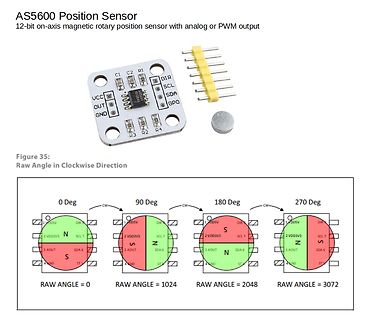
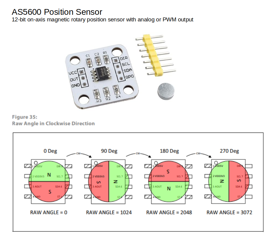
AS5600 Position Sensor
12-bit on-axis magnetic rotary position sensor with analog or PWM output
C1 C2 R1 DIR
UCC SCL
OUT SDA
GND GPO
R3 R2 R4
Figure 35:
Raw Angle in Clockwise Direction
0 Deg 90 Deg 180
arranged in four corners. • Do not press on the panel, edge of the frame strongly or electric shock as this will result in damage to the screen. • Do not scratch or press on the panel with any sharp objects, such as pencil or pen as this may result in damage to the panel. • Protect the module from the ESD as it may damage the electronic circuit (C-MOS). • Make certain that treatment person’s body are grounded through wrist band. • Do not leave the module in high temperature and in areas of high humidity
network for touch currents between each exposed metallic part on the set and a good earth ground such as a water pipe, as shown in Figure 1. 3. Use Leakage Current Tester (Simpson 228 or equivalent) to measure the potential across the measuring network. 4. Check each exposed metallic part, and measure the
pages allocated by Function 4 and Function 27 (Allocate Standard Pages subfunction) are referred to as pages and are 16K bytes long. Logical pages allocated by Function 27 (Allocate Raw Pages subfunction) are referred to as raw pages and might not be the same size as logical pages. CALLING PARAMETERS
Wie wäre es mit einem "magnetischen Drehpositionssensor", z.B.: AS5600 Anstelle der Scheibe einen kleinen Magneten auf die Drehachse setzen. Der Sensor kann sogar hinter Kunststoff wasserdicht verbaut werden und hindurch messen, hab ich selber schon probiert.
Max Unit Forward voltage I =200mA V 1 V F F Document Number 85608 www.vishay.de FaxBack +1-408-970-5600 Rev. 3, 01-Apr-99 1 (5) BZX85C... Vishay Telefunken Type VZnom ZT for V ZT and rzjT rzjk at ZK IR at VR TKVZ 1) BZX85C... V mA V W W mA mA V %/K 2V7 2.7 80 2.5 to 2.9 < 20 < 400 1 < 150 1 –0.08 to –
Max Unit Forward voltage I =200mA V 1 V F F Document Number 85608 www.vishay.de FaxBack +1-408-970-5600 Rev. 3, 01-Apr-99 1 (5) BZX85C... Vishay Telefunken Type VZnom ZT for V ZT and rzjT rzjk at ZK IR at VR TKVZ 1) BZX85C... V mA V W W mA mA V %/K 2V7 2.7 80 2.5 to 2.9 < 20 < 400 1 < 150 1 –0.08 to –
funktionierend aber leider ist die Datei verschwunden ò_Ò. Ich möchte derzeit erstmal nur den RAW Angle ausm AS5600 auslesen mit meinen PIC18f. Code übern MCC generiert weil ich weiß, dass es mal funktioniert hat. Aber es kommt nur komsiches Zeug bei raus. Ausgeben lasse ich es aufn einen kleinen OLED Display
option, the DIP 14 Series is a relay package that allows for automatic insertion directly on PCBs as well as insertion into standard 14 Pin DIP sockets. FEATURES RATINGS (@ 25˚ C) All position mercury contacts on some models Parameter Min Typ Max Unit Stable contact resistance over life 4000 Vac input-output
vertically mounting high perform- ance MH4 contact. There is a choice between plastic and metal covers, as well as non-encapsulated types for lower capacitance.The CUPV models offer high input to output isolation and are BS EN 60950 approved. FEATURES RATINGS (@ 25˚ C) Standard nominal coil voltages include
>AS5600 https://www.mouser.de/new/ams-osram/ams-as5600-potuino-arduino-shield/ https://www.mouser.de/datasheet/2/588/AS5600_AB-POT_UG000378_1-00-1513605.pdf allerdings 51,32 € Es gibt auch immer noch
Christoph db1uq K. schrieb im Beitrag #7359665: >>AS5600 > https://www.mouser.de/new/ams-osram/ams-as5600-potuino-arduino-shield/ > https://www.mouser.de/datasheet/2/588/AS5600_AB-POT_UG000378_1-00-1513605.pdf > allerdings 51,32 € https://www.mouser.de
Shelf life (at 85 C) After 1000 hours no load test, leakage current, capacitance and tan are same as load life value. The measurement shall be performed at 20 C by the KS C IEC 60384 - 4 DRAWING Unit : mm D 40 PC Board Terminal Insulating sleeve Mounting Holes Terminal 0.8 0.1 0 0.8 .1 1 . 0 0. a 2
imOriginal: ,,sheer policy" MOVED TO 48 KHz THE WORLD WOULD AGREE TOMORROW AND 2 ebenda; im Origina.As for his choice of 44,1 kHz Doi, so far, has never THE EVOLUTION OF THE ALL DIGITAL STUDIO WOULD BEGIN IN presented truly cogent technical facts, and as Philips as CD-system owner A TIDY FASHION." have
kommunizieren 87/2/8 Patos „informiert" 87/14/17 PC-Software von Franzis 87/9/75 Pentagon braucht GaAs 87/12/18 Philips-Bilanz 1986 87/8/22 Philips-Geschäftsbericht '86 (PKI) 87/14/7 Philips in der CSSR 87/12/12 Philips: 60 Jahre in Deutschland 87/3/14 Pkw-Armaturen über der Motorhaube 87/15/12 Post testet
module = 2 mm; pitch diameter = 100 mm. V CC= 12 V;tf = 2 kHz; module = 2 mm. Fig.7 Sensing distance as a function of positional Fig.8 Sensing distance as a function of positional tolerance in the y-axis; typical values. tolerance; typical values. MRA982 MRA962 handbook, halfpage handbook, halfpage d d
option, the DIP 14 Series is a relay package that allows for automatic insertion directly on PCBs as well as insertion into standard 14 Pin DIP sockets. FEATURES RATINGS (@ 25˚ C) All position mercury contacts on some models Parameter Min Typ Max Unit Stable contact resistance over life 4000 Vac input-output

 Bild
Bild
 Bild
Bild