Sericll- Die Fernbedienung basiert auf dem Sy Wandler lator stem ,,IR 60“ . Die vom Fernsteuersender BAS-Signal SDA 2008 ausgesendeten IR-Befehle werden von der Empfängerfotodiode in Bild 59. Signalverarbeitung in einem Datensichtgerät und Ansteuerung durch den Mi elektronische Signale umgewandelt und
Format: <freq>,<leader_mark>,<leader_space>,<mark>,<space>,<mark>,<space>,... z. B. "38000,342,171,21,21,21,64,..." Zeiten in Einheiten von ~26.3 us (1/38kHz-naher Tick), Trägerfrequenz 38 kHz. Das Script extrahiert alle IR-Codes, dekodiert das NEC-Protokoll (Adresse, Kommando samt Prüfbytes) und ordnet
temperature ranges available: l Powerful 16-bit compare/capture unit 0 to 70 C (T1) (CCU) with up to 21 high-speed or PWM – 40 to 85 C (T3) o output channels and 5 capture inputs – 40 to 110C (T4) l Versatile "fail-safe" provisions l Plastic packages: P-LCC-84, l Fast 32-bit division, 16-bit multiplication
Ursache dafür ist, dass die anonymisierten Antworten zentralisiert gesammelt werden. Diese Knowledge Base dient dann erstens zur Beantwortung weiterer Fragen und zweitens zur Weiterentwicklung der Produkte und der Applikationsliteratur. ### Trumpf TruPlasma – Plasmagenerator mit EtherCAT-Interface Am
Signalgeneratoren, die nun wie in der Abbildung gezeigt bis zu 40 GHz erreichen. 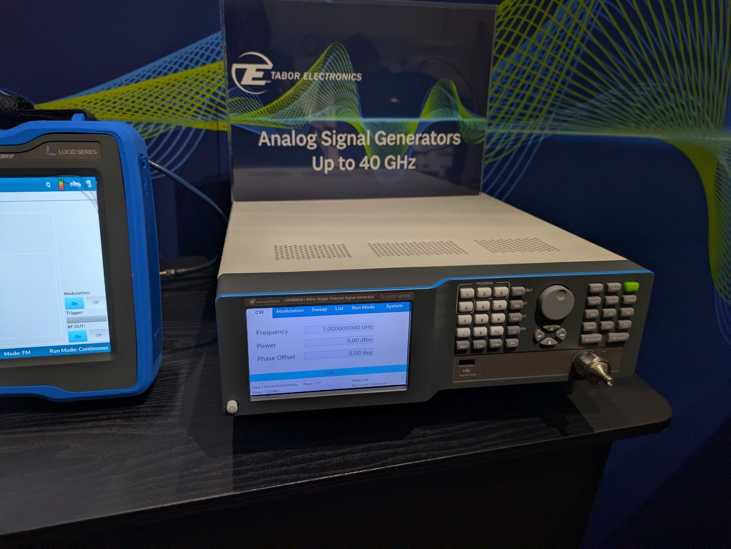 ### Rigol RSA7500 – neuer Spektrumanalysator in Prototypform Im Hause Rigol ist man – offensichtlich – in Sachen RF-Testgeräten auf den Geschmack gekommen. Mit dem Rigol RSA7500 zeigt man nun
706114/1.png) Bildquelle: Infineon. ### Microchip EVB-LAN8670-USB-D bzw EV62B92A – USB-zu-10BASE-T1S-Konverter Microchip bietet mit dem LAN8670 seit einiger Zeit einen PHY an, der ein Ethernet-Interface für 10BASE-T1S zur Verfügung stellt. Mit dem EVB-LAN8670-USB-D gibt es ein Evaluationsboard
Weitere Informationen zu den Leistungsdaten finden sich in der Tabelle. 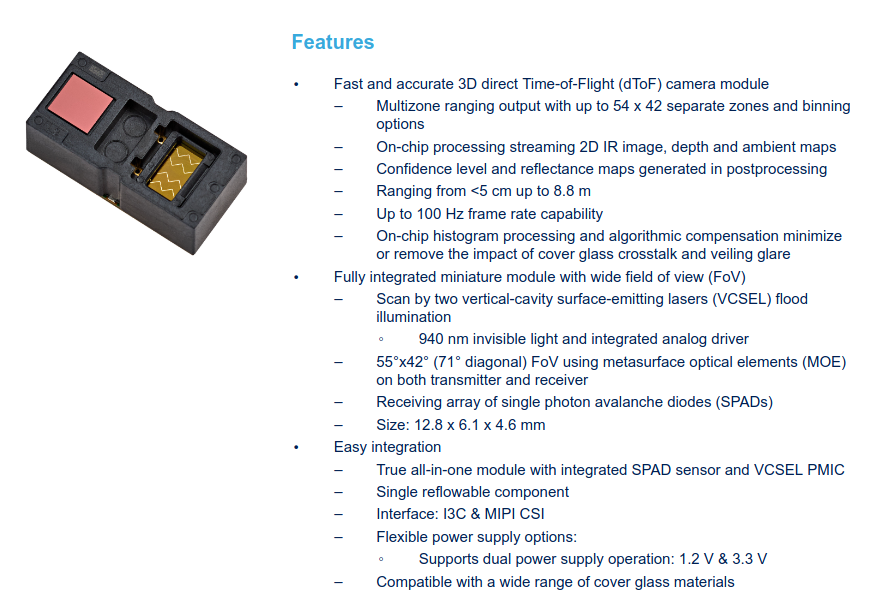 Bildquelle: STMicro Zur Erinnerung hier noch eine Beispielausgabe – man beachte, dass die Farben den Abstand des jeweiligen Objekts zum Sensor beschreiben. 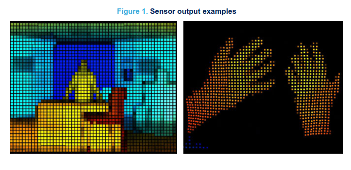
17 Optical control check 18 Temperature buttons 19 Fixed temperature display 20 Special functions 21 Funnel insert 22 Soldering tip compartment 23 Cleaning element WD 1 (M) / WD 1000 (M) 3-18 E Contents D N 1 About these instructions ............................................................3 2 For
Akku Keeppower P2160TC, geschuetzter 21700 mit Type-C Nennspannung 3.6 V Kapazitaet 6000 mAh / ca. 21.6 Wh Abmessungen ca. 21.8 x 76.8-77 mm Max. kontinuierliche Entladung 10 A USB-C Ladestrom ca. 1.5 A Hersteller-Ladezeit ca. 4 h Standardwert Projektziel 4-5 h Laden; 7-8 h Betrieb Feuerhand Beat Lantern
/1714] Building C object esp-idf/esp_wifi/CMakeFiles/__idf_esp_wifi.dir/src/smartconfig_ack.c.obj [21/1714] Building C object esp-idf/wpa_supplicant/CMakeFiles/__idf_wpa_supplicant.dir/port/os_xtensa.c.obj [22/1714] Building C object esp-idf/esp_wifi/CMakeFiles/__idf_esp_wifi.dir/esp32s3/esp_adapter.c.obj
device, ULN2003AI device, and ULQ2003A devices, V IH = 3 V‹ S12: ›The ULN2003A device has a series base resistor to each Darlington pair, thus allowing operation directly with TTL or CMOS operating at supply voltages of 5 V or 3.3 V.‹
ULN2003AI device, > and ULQ2003A devices, V IH = 3 V‹ > S12: ›The ULN2003A device has a series base resistor to each Darlington > pair, > thus allowing operation directly with TTL or CMOS operating at supply > voltages of 5 V or 3.3 V.‹ Man könnte natürlich auch einfach jedem Leistungsausgang
All USB registers are 16 bit width but they must be accessed with 32 bit instructions. #define USB_BASE 0x40005C00 #define USB_EpRegs(x) (*(volatile uint32_t *)(0x40005C00 + 4*(x))) #define USB_EP0R (*(volatile uint32_t *)(0x40005C00)) #define USB_EP1R (*(volatile uint32_t *)(0x40005C04)) #define USB_EP2R
EpTable` lives in the USB **packet memory / buffer descriptor table (BTABLE)**: - USB register base: `0x40005C00` (`EP0R=+0x00`, `CNTR=+0x40`, `ISTR=+0x44`, `DADDR=+0x4C`, `BTABLE=+0x50`) → the STM32-style USB FS device peripheral. - Packet memory base: `0x40006000`, with `USB_BTABLE = EpTableOffset
des volatile kommt diese Warnung: ``` ../Src/usb.c: In function 'DoGetStatus': ../Src/usb.c:1004:21: warning: storing the address of local variable 'Buf' in 'CMD.TransferPtr' [-Wdangling-pointer=] 1004 | CMD.TransferPtr = Buf; | ~~~~~~~~~~~~~~~~^~~~~ ../Src/usb.c:927:13: note: 'Buf
Text hat um die 60kB. Ein krasses Mißverhältnis von 25:1. Keks F. (keksliebhaber) 04.08.2026 21:16 #8082157 > Man kann leider nicht mehr sehen WER den letzten Beitrag verfasst hat. Wo sieht man in der Thread-Übersicht, wer den letzten Beitrag eines Threads schrieb? DAS wäre mal eine wichtige
the scale on its side to disassemble and mount the display unit. Unfasten the Allen screws on the base plate and remove the base plate. Remove the fastening screws. 1–16 Remove the screws on the retainer plate. Then set the scale back upright. Remove the screws on the base (7). Lay the support arm along with the base and the display unit on a table. Remove the plugs from the long side of the scale (insert them in the holes on the short side). Loosely attach the display unit with the support arm and base to the long
plugin/quectel] could not grab port ttyUSB0: Cannot add port 'tty/ttyUSB0', unhandled port type Aug 03 21:42:30 chupi ModemManager[973]: <msg> [base-manager] modem for device '/sys/devices/platform/axi/1000120000.pcie/1f00300000.usb/xhci-hcd.1/usb3/3-1' successfully created Aug 03 21:42:30 chupi ModemManager[973]: <msg> [base-manager] running setup for device '/sys/devices/platform/axi/1000120000.pcie/1f00300000.usb/xhci-hcd.1/usb3/3-1'... Aug 03 21:42:31 chupi ModemManager[973]: <msg> [modem1] state changed (unknown ->
Bild von mir entgegen zu kommen: nix Whatsapp (*) :) *: Aber Threema, Foto, Fahrplan, Knowledge Base, KI uvam.
H. H. schrieb im Beitrag #8107638: >> 24.10.2026 21:57 >> Was sind denn diese blauen 27 C9 - Neosid lässt mich eine Induktät >> vermuten? > > 24.10.2026 22:00 > 27µH Spulen, Baureihe Sd75. C9 ist der Datecode, September 1992. Erst nach drei Minuten
. Æ Use the Y-axis tensioning keys to pre-tension the toothed belt. Æ Install the component table base plate, secure the fastening screws with loctite and assemble the component table guidance. Æ Secure the screws of the component table base plate with loctite. Æ Install the cutter and the empty-table
0xAA. This register is read/write. Memory Space Configuration Register Name Index Definition Memory base address 0x40 Read/write value indicating the selected memory base address bits[23:16] for bits[23:16] descriptor 0 memory descriptor 0. This is the Boot Prom Space. Memory base address 0x41 Read/write
Bandwidth (IN position). 20. CH I: 1 mV/div Y-Amplifier Bandwidth – All other pushbuttons (Out Position!). 21. CH II: 1 mV/div Y-Amplifier Bandwidth – Rotate the three variable controls (TIME/DIV. and VOLTS/ 22. X-Magnification x1 DIV.) to their (calibrated) detent positions. 23. Time Base – Set TIME/DIV. switch
address and addressing mode of the exception or interruptfunction are defined bythe exception entry base address register mtvec. mtvec[31:2] defines the base address of the exception or interrupt function. mtvec[1:0] defines the addressing mode of the handler function, where mtvec[0] defines the entry
with Base series bases. To prevent damage to the device, do not stack Core2 v1.3 with any Base series expansion base. • When stacking Core2 v1.3 with M5 modules, you will need to remove the battery bottom
Protokolle: [c] ISO 14443A, ISO 14443B, FeliCa™, and ISO 15693 protocols [/c] ### Atomic Audio-3.5 Base Wer Sprachinformationen ein- oder ausgeben muss und dafür ein Audio-Frontend benötigt, wird von M5Stack mit der in der Abbildung gezeigten Atomic Audio-3.5 Base bedient. . The halted `pc=0x1c1a6` / `lr=0x1d495` both fall inside that application. `0x1B000` = 108 KB is the
DES COMPOSANTS 6. Mesurer la température finale de l’eau. (Exemple: La température finale est T2 = 21°C) 7. Calculer la puissance de sortie des micro-ondes P en Watts à l’aide de la formule ci-dessus. Températureinitiale ................................................................................
embedded servo information on the disk surface. Commonly, a servo writer uses a large, massive granite base to minimize the effects of vibration. The servo writer can also use precision fixtures to hold the target drive, a precision, laser-interferometer-based actuator arm positioning mecha nism to place
abfragen. [pre] ~# smartctl -t long /dev/sda smartctl 7.2 2020-12-30 r5155 [x86_64-linux-5.10.0-21-amd64] (local build) Copyright (C) 2002-20, Bruce Allen, Christian Franke, www.smartmontools.org === START OF OFFLINE IMMEDIATE AND SELF-TEST SECTION === Sending command: "Execute SMART Extended
200kHz-Wellenformen-Wiederaufladbarer/dp/B0GWQSPNL5?source=ps-sl-shoppingads-lpcontext&psc=1&smid=APPEGJJ21UU6W Notfalls noch ein Verstärker mit DIY > Antenne erweitern.
habe einen kleinen Test bezüglich LF Reichweite mit einem Atmel ATA5291 (PEPS Driver and Immobilizer Base Station) gemacht, der ist etwas neuer aber im Prinzip ähnlich dem weiter oben erwähnten Atmel ATA5279C. Die LF Antenne (Premo KGEA-BFCWX-B-0345J) ist dazu passend und wird so ähnlich auch in Fahrzeugen
E D A11 u PD4(T0/XCKPCINT20) 2 U N N P D D +5V 0 0 18 9 V V C C G V + 1 1 20 AVCC PD5(T1/OC0B/PCINT21) 10 2 2 2 2 2 2 n AREF PD6(AIN0/OC0A/PCINT22) 11 1 6 1 PD7(AIN1/PCINT23) C C 3 C PB0(ICP1/CLKO/PCINT0) 12 PB1(OC1A/PCINT1) 13 5 T6 21 AGND PB2(SS/OC1B/PCINT2) 14 + BSS123 2 4 PB3(MOSI/OC2A/PCINT3) 15
EGNOS designation WAAS designation MSAS designation Reference Base Station RIMS: Reference and WRS: Wide Area Base GMS: Ground Monitor Integrity Monitoring station Station Station Control Center MCC: Mission Control WMS: WAAS Master MCS: Master Control Center Station
extension called Walk-By/Drive-By Reading will enable LoRaWAN devices to efficiently connect to mobile base stations that might be mounted on vehicles, flown on drones, or carried by hand. This extension will be especially valuable in cases where devices fall outside the coverage of fixed network infrastructure
H.A. Westra ... 6-20 the existing range of elektor software service reader services. coming soon 6-21 mini counter Elsewhere in this issue a highly sophisticated 250 MHz counter isdescribed. The heart of that instrument is an LSI p. 6-20 counter 1C from Mostek, the MK 50398N. By using the same prove
Ratings Value Unit VCEO Collector-Emitter Voltage 45 V VEBO Collector-Emitter Voltage 45 V VCBO Emitter-Base Voltage 7 V VCEX Collector-Emitter Voltage VBE-1.5 V 50 V C Collector Current 15 A B Base Current 7 A PT Power Dissipation @ T C 25° 117 Watts TJ Junction Temperature -65 to +200 °C TS Storage Temperature
OUT terminal is in electrical D 0.001%/V Typical Input Voltage Regulation contact with the mounting base. D 76-dB Typical Ripple Rejectionegulation TO-220AB D Standard TO-220AB Package IO A description high-voltage regulator with an output range of capable of sourcing more than 700 mA. It isr e performance
VOUT Unlike older NPN-pass transistor designs, where the minimum dropout voltage is limited by the base-emitter • Input Voltage, IN voltage drop and collector-emitter saturation voltage, First, calculate the power dissipation of the regulator dropout performance of the PNP output of these from these numbers

 Bild
Bild