AMD PLD PAL16R8D/2 NONE No Need WPLD1 V5.10 AMD PLD PAL16R8H-10 NONE No Need WPLD1 V5.10 AMD PLD PAL20L8-10/2 NONE No Need WPLD1 V5.10 AMD PLD PAL20L8-4 NONE No Need WPLD1 V5.10 AMD PLD PAL20L8-5 NONE No Need WPLD1 V5.10
Anschlusses J1 die positive Spannung an und auf Pin 1 die negative, dann fließt der Strom durch R1 durch, da D1 sperrt. D2 lässt den Strom ungehindert passieren und über R2 fällt keine Spannung ab. Verwende ich statt RB einfach die Relaisspulen, funktioniert die Schaltung. Jeweils ein Relais zieht an, wenn ich
da ich dort schon eine Lösung für hatte. Natürlich wäre es sinnvoller, eine H-Brücke oder einen LM293D oder dergleichen zu verwenden. Vermutlich werde ich diesen Schritt auch gehen, doch diese Betrachtung ist für mich erstmal zweitrangig. Zuverlässiger Kontakt ist wichtiger! Axel S. schrieb im Beitrag
o a e f e n t e c a v p A c R R R R R R i t gn e g l e 6 2 4 6 s 5 2 5 2 5 2 c d l t i d 1 R 1 r r l re h d f A I s e 1 y ! i o i E i t A a t c t n D F 1 3 5 g h te a . o i t u S 1 i t i i e n c e l 3 A i u l m c s i h p 3 W s n h n e t t u a r t o l n
R V E E V E E X V I I I I V O O V D T T T T E B S P P P P D P P P P D L L D L L D A C C D D A D D A 2 1 0 9 8 7 6 5 4 3 2 1 0 9 8 7 6 5 4 3 2 1 0 9 8 7 6 5 4 3 2 1 0 3 3 3 2 2 2 2 2 2 2 2 2 2 1 1 1 1 1 1 1 1 1 1 0 0 0 0 0 0 0 0 0 0 1 1
0 3 0 R R 0 1 1 1 1 1 R 6 V 7 V RR K 5 2 L L L n 5 4 3 2 5 T X D X N K 72 7 2 1 R R R D D D E C C C C 1 u A o A G 3 65 3 4 4 4 2 L 4 3 2 D 8 7 7 2 0 I I I C C C s I u 1 L 3 6 5 4 3 D 1 1 8 5 2 / C C CC 1 1 1 1 a . m N E R 0 1 0 98 8 7 6 2 , C
bisherige Idee wäre ungefähr folgender Aufbau: Teensy 4.0 und einem PJRC Teensy Audio Adapter Board Rev D mit vorgelöteten Pins. Als Schallwandler hatte ich den Kemo L010 Ultraschall-Piezo-Lautsprecher im Blick. Mir ist aber unklar, ob dieser Aufbau für reproduzierbare Testsignale im Bereich von ca. 20–60
nötig. Für den TE böte sich ein Arduino UNO an, als Endstufe ein billiges Shield-Platinchen mit L293. Als Netzteil wird ein einfaches Steckernetzteil mit 12V reichen.
ausgedacht, gewöhnliche Schüler können da nicht mitreden. 1) https://en.wikipedia.org/wiki/David_L._Mills
steht. Ein vernünftiged Progrmm mit GUI hätte ein erklärendes Mouseover & Platz für Einheiten... :D Norbert schrieb im Beitrag #8060818: > die > können nämlich man-pages und RFCs lesen NEEEEEEERD
+3.0dB Power at receiver input -160dBW (-130dBm=100.0*10 W) -18 Table 6: L1 carrier link budget analysis modulated with the C/A code 14 Global Positioning System, Standard Positioning System Service,Signal
d S _ E I S A v B L T T T L e B C O U U R W e B C K K K T R D A C L L I P L T L C C _ D A Reset 0 0 0 0 0 0 0 0 0 0 0 0 0 0 0 0 S32K1xx Series Reference Manual, Rev. 13, 04/2020 170 NXP Semiconductors
7 85 m e s t 2 k H 2 1 SIGNA1L3 A L E P I N11 D1911 . LOGIC 0 . ' RE312KKZ S I G N A L 14 A L E PIN 11 D1904 . LOGIC 0 : L I S G k H z S I G N A1L5 A g P I N 2D I 9 0 8 : LOGIC 0 Ae7BkKHz 1 S I G N A L 16 . A l . PIN 5 D 1 9 0 6 LOGIC
P Y I ) I T -11 ( -8 EADCI 3 I E 10 T 10 10 I R N S R E E U 10 -12 R 10-9 102 S C U S R C U A K O D 10 -13 R 10-10 101 I E D DARK CURRENT M O L N -14 -11 0 E A 10 10 10 D T O E A L 10 -15 10-12 10-1 A 500 1000 1500 2000 I Q E SUPPLY VOLTAGE (V) THBV4_0445EA Figure 4-45: Example of EADCI THBV4_0445EA
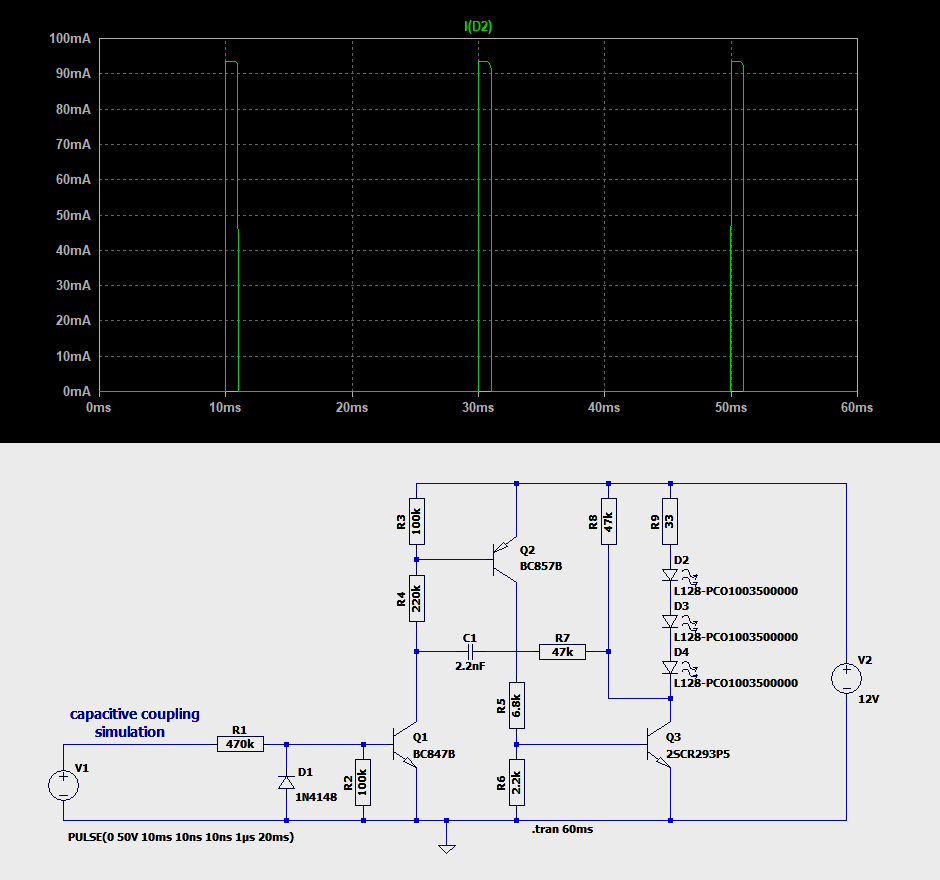
Dieter D. schrieb im Beitrag #8017667: > und misst Dieter D. schrieb im Beitrag #8017667: > misst So weit ich den Vorgang verstanden habe, wird beim TE nur innerhalb LTSpice simuliert und bisher noch
SK 04/100/SA 1.7 k/W und 180Ws/K -> 306s der ist aber auch mit dünneren Rippen, wie geschrieben d hat einen Einfluss oder ICK 6 8 L 83kW ~ 0.5Ws/K der wiegt 1/5000 vom SK47, aber die zeitkonstante ist mit 42s etwas weniger als 1/26 Wenn man jetzt die genannten Kühlkörper vergleicht sieht
NTCLE100E3 www.vishay.com Vishay BCcomponents PACKAGING TAPE SPECIFICATIONS Thermistors on tape P T D P H H 2 H3 d D0 H 1 L H W 0 A W 1 W W 2 P0 P1 F Direction of unreeling t Taped according to IEC 60286-2 (cover tape may differ from shown) 1E pitch NTCLE100E3...T1 detail A DIMENSIONS in millimeters
xxxxxxxxxxxxxxxxxxxxxxxxxxxxxxxxxxxxxxxxxxxxxxxxxx xxxxxxxx C P M xxxxxxxxxxxxxxxxxxxxxxxxx xxxxxxxxxxxxxxxxxxxx xxx N O r R M d 5 X P u 2 P N t S Y a ADDRESS DATA e P a m U s RX L e SA A0 A1 A2 A3 A4 A5 (1)R/W SO SA D0 D1 D2 D3 D4 D5 D6 D7 SO c C e o t n d u c o r ADDRESS s TX SA A0 A1 A2 A3 A4 A5 (1) R/W SO l f m o R p e v . d MX . n — s 1 o DTRQ 1 7 m 001aak589 9 A n S p s a l b (1) Reserved. n 2 c d 1 o Fig 10. UART write data timing diagram a 6 g d d p l Remark: The data byte can be sent directly after the address byte
meet all of the desired operating conditions www.controltechniques.com 7 t io n fl e x i b i lit y d e a s y in t e g r a e S P , fa s t a n U n id r iv Applications with PLC or Motion Functionality External Control SM-APPS-LITE-V2 SM-APPS-PLUS SM-REGISTER SM-EZMOTION 2000, XP, Vista 32 orgrammable
ID Palette Register (RK, GK, BK) CS* VSL PWM Grayscale G System Interface Circuit N RS - 16 bit 16 D Bit Operation E/WR*/SCL - 8 bit - Clock 16 synchoronized 16 RW/RD * - 12 G serial a DB0/SDI, s DB1/SDO, 16 L c L e Write da64 t e t m to DB15 Read data latch h s h e latch C l C t SEG1 to c c c d 48
NTCLE100E3 www.vishay.com Vishay BCcomponents PACKAGING TAPE SPECIFICATIONS Thermistors on tape P T D P H H 2 H3 d D0 H 1 L H W 0 A W 1 W W 2 P0 P1 F Direction of unreeling t Taped according to IEC 60286-2 (cover tape may differ from shown) 1E pitch NTCLE100E3...T1 detail A DIMENSIONS in millimeters
Wechselzyklus nicht ins Gewicht. Ich verwende sie u.a. auch in Heizkörperthermostaten, dort halten sie i.d.R. mehr als zwei Jahre.
Energizer Lithium korrelieren mit deren Datenblatt, sind also plausibel: http://data.energizer.com/pdfs/l92.pdf Wieviel Kapazität hast du bei den Varta Lithium AA gemessen und bei welchem Strom?
E S S _ S _ H V V P A B C _ C N C D + D C L C R I I L P H C T U H U O T D T B2 C2 D C257 C268 Y T K I W R H T T T L A Y F T T V T T T A C Y 2 1 D L L L S U O S T U T Z - 1 - G P D S O _ S 3 P I R S S _ Y P L O P P D & Y P H H C 4 4 I 2
H P C E R L L R W C A T O O O D C T _ 3 _ V C O D _ 2 V 1 _ D R D D R S C KEY&NFC WF11 E Y E . F E E . Y + Y 6 7 5 G 3 6 1 4 L 2 G 0 L L _ _ FRONT L K L 3 N R L 3 K A K + D D D D D D D E D D D E E L E CJP27GB116ZY
allem Motorleitungen, ist allerdings unterschiedlich. M1 und M2 sind Motoranschlüsse. U2 ist ein L293D H Brückentreiber. Controller ist ein ESP32. Bauteile sind vorgegeben und fix. Geht "nur" ums routing. Benötigt ihr noch andere Infos ? Bin gespannt was so kommen wird :)
Allerdings noch ohne Pull-Down 47k Ohm) Betriebsspannung sind 2 LiPo Akkus in Reihe, also ~7,4V für den l293d. Die 5V sind für die Sensoren und den ESP. Sind 2,2k Ohm nicht etwas zu niedrig für Pull Down?
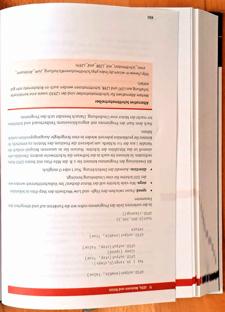
450
http://www.rn-wissen.de/index.php/Schrittmotoren_mit_L297_und_L297n
Weitere Alternativen für Schrittmotortreiber sind der L293D sowie eine kombinierte
Schaltung aus L297 und L298. Danach beendet sich das Programm.
Nach dem Start des Programms mit angeschlossenem
refroidir dents. un accumulateur • Chargez vos bat- chaud avant de teries uniquement à procéder au char- l‘intérieur d‘un local gement. car le chargeur n‘a • N‘ouvrez pas été conçu que pour l‘accumulateur et ce type d‘utilisation. évitez tout dom- • Pour réduire le mage mécanique risque d‘une dé- à l‘accumulateur
TOOL4COOL® applicable Electronic units (voltages & code numbers) Compressors Compressors r C r C D ) r V r V R134a V S v 4 v 4 H d C ( C o - o - i 0 Applications T D D D Code e D 1 d D 6 C 0 1 C 0 2 o D 0 A V V F B H N H H L numbers S 2 N p 2 N / 1 N / 1 N m V N F F F F F F F K F F C C 0 0 0 0 l 2
PORT - I/O Pin Configuration 16.2.1 Block Diagram Figure 16-1. PORT Block Diagram Pull-up Enable DIRn D Q R Peripheral Override OUTn D Q Pxn Peripheral Override R Invert Enable Synchronizer INn Synchronous Input Q D Q D R R Sense Configuration Interrupt Interrupt Generator Asynchronous Input/Event Input
1 3 3 3 D 2 1 1 74HC08 IC7B D D 4 6 5 74HC08 116 117 Feb.2005 G-70 CIRCUIT DIAGRAM (LEFT CONTROL 4/6) 8 8 8 8 8 8 8 D D D D D D D L L L L L L L D83 D84 D85 D86 D87 D88 D89 SLR-343EBT3F SLR-343EBT3F SLR-343EBT3F
D CH1 (111) 118 119 Downloaded from www.Manualslib.com manuals search engine Feb.2005 G-70 CIRCUIT DIAGRAM (LEFT CONTROL 5/6) 0 1 2 3 4 5 6 D D D D D D D L L L L L L L D90 D91 D92 D93 D94 D95 D96 SLI-343URC3F
Metravolt 10 D Spannungsprüfer ISO 42,22 6808 Metrawatt Metravolt 5 Spannungsprüfer ISO 42,22 6809 Metrawatt Metrawid 2 Analogmultimeter ISO 56,70 6797 Metrawatt Metrawid L Widerstandsmessgerät ISO 56,70 6799 Metrawatt
L D A P APPLICATION NOTE 6 0 E V 0 PulsedOver-CurrentDrivingofXLampLEDs: Information and Cautions INTRODUCTION The applications support team at 2. Repetitive pulsing (e.g. pulse- current” situation (that
capacitance and tan are same as load life value. R E T DRAWING Unit : mm Y P E S Insulating sleeve d 0.05 Tinned copper-ply wire x D 5 6.3 8 10 12.5 16 18 22 25.4 m P 2.0 2.5 3.5 5.0 5.0 7.5 7.5 10.0 12.5 . P 0.5 0 d 0.5 0.5 0.6 0.6 0.6 0.8 0.8 1.0 1.0 D 0.5 1.0 L max. 15 min. 4 min. 1.5 2.0 Safety
ww.st.com. ECOPACK is an ST trademark. 2.1 SMB package information Figure 13. SMB package outline E1 D E A1 C A2 L b Table 3. SMB package mechanical data Dimensions (1) Ref. Millimeters Inches Min. Max. Min. Max. A1 1.90 2.45 0.0748 0.0965 A2 0.05 0.20 0.0020 0.0079 b 1.95 2.20 0.0768 0.0867 c 0.15 0.40 0.0059 0.0157 D 3.30 3.95 0.1299 0.1556 E 5.10 5.60 0.2008 0.2205 E1 4.05 4.60 0.1594 0.1811 L 0.75 1.50 0.0295 0.0591 1. Values in inches are converted from mm DS0684 - Rev 14 page 6/12 SM6TxxA, SM6TxxCA Package information
is omitted due to 1 same as L-ch. +2.5V VDDI T N T O IN K +3.3V P S C A S R M D D C L VDDE G B H H X P H H H 68 56 36 32 2 113 35 33 34 Q1601 INV. 95 96 97 98 94 100 1 2 3 4 5 6 7 18 19 20 8 9 10 12 13 TUNER/ L C D O L T A P S C
als Beispiel einen 75HC4411 als Open Source Halbleiter umsetzen. Der SN754411 ist ein verbesserter L293, aber immer noch TTL. Ich fände es schön, wenn es eine 1:1 austauschbare CMOS-Variante davon gäbe. Das ist doch eigentlich ein relativ einfaches IC. Das sollte man problemlos selbst entwerfen können
Beispiel einen 75HC4411 als Open Source Halbleiter > umsetzen. Der SN754411 ist ein verbesserter L293 Warum sollte man diesen alten Schrott nachbauen wollen. Mir sind die L293 und L298 regelmäßig abgebrannt. Es sind haufenweise fertige Treiber in MOS und mit Schutzschaltungen verfügbar. Such

 Bild
Bild
 Bild
Bild
 Bild
Bild
 Bild
Bild
 Bild
Bild
 Bild
Bild
 Bild
Bild