. #define USB_IRQ_NUMBER 20 // Buffer for sending characters, txLen must be 4, 8, 16, 32, 64, 128, 256, 512, 1024, 2048, ... #define USB_TXLEN 256 // Buffer for received characters, rxLen must be 128, 256, 512, 1024, 2048, ... #define USB_RXLEN 256 // Vendor and product ID of the USB device #define VID
Tagen. Der Vorschlag von Mani (Rauf-Runterzählen) klingt gut. Die zu messende Differenz könnte auf max. 2 Stellen (99 Sekunden) begrenzt sein. Mehr als 10 Sekunden wären ohnehin eine Katastrophe. Grüße Bernd
6.5536 ms Der Tick-tock interval ist maximal 7.1 Minuten (16 bit). Der Tock Intervall ist maximal 256 x Tick-tock Derzeit maximal 14 reload Timer mit 15bit Wertebereich.
may differ. 3.2 Electrical Characteristics (VDD+5V±5%, GND=0V, T=+25°Ca Item Symbol Condition Min Max Unit Notes s Operating Volatge V DD 4.5 5.5 V Input voltage "H" V V -2.2 V V 1, 3 IH DD DD "L" V IL 0 0.8 V 1, 2, 3 Output voltage "H" V OH V DD.3 V DD V 3 "L" V 0 0.3 V 3 OL Output Resistance "H" R
4 6 8 10 12 14 16 4 8 12 16 20 24 28 32 V−DOTS 16 32 48 64 80 96 112 128 32 64 96 128 160 192 224 256 1 SCREEN 2 SCREENS MD2 H L H L MD2 Input Pins for selection of number of columns MD3 H H L L MD3 Columns 32 40 64 80 FS0 H L H L FS0 FS1 H H L L FS1 Input Pins for selection of font Font 5 × 8 6 × 8
ketten mitdoppelter Aufzeichnungsdichte Betrieb zunehmend an Bedeutung ge stimmten Sektoradresse 256 Informatio und 5.25"-Floppys für High-Density-Auf- winnt, wollenwir diese Stellungnahme un zeichnung. Beide können beispielsweise seren Lesern nichtvorenthalten. mit16 Sektoren zu 256 Bytes in 79
Save-Schaltfläche. Die automatische Helligkeitssteuerung verwendet dann bei einer Helligkeitsmessung diese Min-/Max-Werte zum Vergleich. Somit kann der Helligkeitsbereich bei der automatischen Helligkeitssteuerung komplett ausgenutzt werden. Hinweis: Es ist nicht sinnvoll, bei der Max-Messung einfach eine Taschenlampe
bestimmten Anzeigemodi. Bugfix SK6812: Rot und Grün vertauscht. Bugfix LDR: Nach dem Setzen eines neuen LDR-Max-Wertes wurde dieser nicht zurück an das Web-Interface übertragen und deshalb dort (bis zum nächsten Reboot) ein alter Max-Wert angezeigt. STM32 Version 2.1.0. Auslagerung des HTML-Codegenerators auf
Everything runs off the 32.768 kHz ULP oscillator (20 MHz osc stays off). * PWM: TCA0 with PER = 127 -> 256 Hz, 128 levels. While the LED is off the CPU * sits in POWER-DOWN (~0.1 uA, wake on PA1 edge), while on in IDLE so the PWM * keeps running. The PIT (7.8 ms tick, CYC256 of 32.768 kHz) only runs while
7.2.9 Replacing the Complete Lifting Table Cylinder [00358703-xx] . . . . . . . . . . . . . . . . 256 7.2.10 Replacing the Stepping Motor of the Width Adjustment System [00367174-xx]. . 258 7.2.11 Replacing the Limit Switch for the End Position Width Adjustment System [00365108-xx] 260 7.2.12 Replacing
128er 2,5" SSD reicht für Linux oder WIN11 und ist bei Kleinanzeigen ab 10€ zu bekommen (besser eine 256er SSD, die gehen bei 20€ los). Eine 256GB Speicherkarte zum Datenlagern ist immer wieder für 10€ zu bekommen. Ein einzelnes 8GB PC3 SODIMM gibt es ab 15€. Mit dann 10 oder 12 statt 4GB kommt man
Wolf17 schrieb im Beitrag #8081746: > Eine 256GB Speicherkarte zum Datenlagern ist immer wieder für 10€ zu > bekommen. Backup bereithalten: Billige Speicherkarten halten Daten ohne Strom eher nicht so gut. Wolf17 schrieb im Beitrag #8081746
Recommendations Following is the recommendation for manual 300 soldering with a soldering iron. 260°C 2+3seconds max 250 First Wave Second Wave Recommended Soldering Temperature 400 )00 ( ∆ T < 150°C 350 r Cooling t C r50 Preheating ca. 2°C/second e 300 p ca. 3.5°C/second typical t e ca. 5°C/second e 250 100 T preheat
25 C both polariti1s Q (PNP)2& Q (NPN), unless otherwise noted) G = Pb-Free Package Rating Symbol Max Unit (Note: Microdot may be in either location) Collector-Base Voltage VCBO 50 Vdc *Date Code orientation may vary depending up- on manufacturing location. Collector-Emitter Voltage VCEO 50 Vdc Collector
Number of cores</small></td><td valign="center"><small><font color="#0000A0">6 (max 6)</font></small></td></tr> <tr valign="top" bgcolor="#FFFFFF"><td width="300"><small> Number of threads</small></td><td valign="center"><small><font color="#0000A0">12 (max
a peripheral device specially designed for I/O type MCU used to expand the display capability. The max. Display segment of the device are 256 patterns (32×8). The ET6622 is a memory mapping and multi-function LCD controller. Features ⚫ Operating voltage: 2.7V~5.2V ⚫ Built-in 32 kHz RC oscillator ⚫ 1/4bias, 1/8duty, frame frequency is 64Hz ⚫ Max.32×8 patterns, 8 commons, 32 segments ⚫ Built-in internal resistor type bias generator ⚫ 3-wire serial interface ⚫ 8 kinds of time base/WDT selection ⚫ Time base or WDT over flow output ⚫ Built-in LCD
UART als Dump schickt. Ich habe selbst mal, weil ich zu faul war eine PC-App zu programmieren den MAX7456 OSD Chip so programmiert: Ein PIC16F59 (Baseline-Core, kann fast nichts, hat viele I/Os) hat auf dem Steckbrett ein EPROM (27C128 oder 27C256) ausgelesen und via Bitbang-SPI-Kommandos an den MAX7456 schickte. Das EPROM enthielt den Inhalt des .MCM-Files als konvertierte Binärdaten.
) über diese Bereiche und du hast den gleichen Effekt. Du kannst auch von beiden Dateien ein sha256 hash erzeugen und die werden identisch sein.
SEEK_HOLE / SEEK_DATA springen da nicht an den selben ort. > Du kannst auch von beiden Dateien ein sha256 hash erzeugen und die > werden identisch sein. Ja, die prüfen die Löcher auch nicht.
at: www.st.com. Figure 56. HiQUAD-64 mechanical data and package dimensions mm inch DIM. MIN. TYP. MAX. MIN. TYP. MAX. OUTLINE AND MECHANICAL DATA A 3.15 0.124 A1 0 0.25 0 0.010 A2 2.50 2.90 0.10 0.114 A3 0 0.10 0 0.004 b 0.22 0.38 0.008 0.015 c 0.23 0.32 0.009 0.012 D 17.00 17.40 0.669 0.685 D1 (1)
können (Blackfin CPLB). Das wären die interessanten Details gewesen, neben klassischer Angaben wie f_max, BogoMIPS, usw. Dann typische Entwickler-Fragen: - Debugging: Kernel-Debugging, oder debugbare Simulationsmodelle vorliegend? (wie Renode-Cosimulation) - Board-Supply-Package: Support vom Hersteller
Linux mit X11 aehnlich schnell und brauchbar wie ein Interactive Unix auf einem 486/33. Natuerlich nur 256 Farben... .-) Interessant fuer Embeddedbetrachtungen sind aber Sharp Zaurus. Die hatten anfang der 2000er einen Intel Xscale mit 400Mhz und 640x400pixel. Da lief eine eigene Grafikoberflaeche Qtopia
da haben, das kann der > Ralph gerne haben. AMD K6 mit Multimediaerweiterung 233 MHz CPU Takt 256 MB RAM. Sowas in der Art. USB-Hub Schnittstellenkarte. Netzwerkkarte, Grafikkarte ATI, COM/LPT Schnittstellenkarte. Western Digital Caviar 2 Gigabyte ciao gustav
@ 24 VDC Digital Input Channels 2 Digital Inputs +13 to +30 V for state 1 -30 to +3 V for state 0 Max. input current: 8 mA Ethernet Interface 10/100BaseT(X) Ports (RJ45 connector) EDS-508A Series: 8 EDS-508A-MM/SS Series: 6 All models support: Auto negotiation speed Full/Half duplex mode Auto MDI/MDI-X
Server/Client, SNTP EDS-405A-PTP models: IEEE 1588v2 PTP (hardware-based) Switch Properties IGMP Groups 256 MAC Table Size EDS-405A, EDS-405A-EIP/MM-SC/MM-ST/PN/SS-SC models: 2 K EDS-405A-PTP models: 8 K Max. No. of VLANs 64 Packet Buffer Size 1 Mbits Priority Queues 4 VLAN ID Range VID 1 to 4094 Serial Interface
Oder BCV62, der geht aber auch nur bis max. 100mA.
einen 8-Bit DAC für die Feineinstellung. Ja, das kostet einen µC mit I2C oder SPI (es gibt beides, ..256A bzw. ..256B). Der Chip verträgt 40 Volt und braucht weniger als 1 V zum Regeln (typ. 300 mV @ 20 mA). 8 LEDs in Reihe sind also kein Problem und für die 16 Gruppen reicht dann ein Chip, ein µC und
Specifications: in the region of 2 kHz. s e n s i t i v i t y : 1 V peak The input signal is fed via the input max. input v o l t a g e :± 5 V peak stage T1 to the clock input of the input i m p e d a n c e :min. 4k7 max. measurement range : 1 MHz counter; diode D6 protects this input against large negative voltages
, 16K) Write Modes Serial EEPROM • Partial Page Writes Are Allowed • Self-Timed Write Cycle (10 ms max) 1K (128 x 8) • High Reliability – Endurance: 1 Million Write Cycles 2K (256 x 8) – Data Retention: 100 Years – ESD Protection: >3000V 4K (512 x 8) • Automotive Grade and Extended Temperature Devices
gleich vom Start weg halbwegs richtig geht. Normalerweise geht der ntpd davon aus, dass die Uhr um max. 128 ms falsch geht, sonst ist die wohl defekt.
DCF ???: t.b.d. diverse Pull-Down: 1.2 mA ALS SFH5711: ca. 0.5 mA RS-232 MAX3223E: < 1.3 mA ohne Last RS-485 MAX3079E: < 1.5 mA unterminiert 4x LDO MIC5236: < 0.12 mA 3x Referenz REF3433: < 0.3 mA OP INA186A1Q: ca. 0.2 mA was-ich-noch-vergaß: ?[/pre]
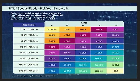
® Speeds/Feeds - Pick Your Bandwidth
• Flexible to meet needs from handheld/client to server/HPC
• Max Total Bandwidth = Max RX bandwidth + Max TX bandwidth
• 35 Permutations yielding 11 unique bandwidth profiles
• Encoding overhead and header efficiency not included
Specifications | Lanes
x1 | x2 |
5V ± 10%; VPPP = VCC ) M2tCe001 Symbol Alt Parameter Test -55 (2) l-70 -80 -90 Unit Condition o Min Max s Min Max Min Max Min Max t t 55 70 80 90 ns AVQV ACC to Outputalid G = VIL - O Valid IL ) ( s ELQV tCE Chip Enable c = VIL 55 70 80 90 ns Valido Outputu o d GLQV tOE OutputEnable E = VIL 30 35 40 40
Nico schrieb im Beitrag #8045926: > 256 Kanal PWM an seine Grenzen Dir ist schzon klar, dass ein LED-Treiber mit einer höheren Ausflösung ein anderes, längeres Protokoll erfordert, oder?
im Beitrag #8045926: > Der kommt aber vorallem beim faden der Glühbirnensimulation mit seiner > 256 Kanal PWM an seine Grenzen. Die Stufen sind vorallem beim auf oder > nachglimmen eindeutig erkennbar. Das ist so nicht akzeptabel.
]+-----------------------------------------------------------------------------+ | NVIDIA-SMI 470.256.02 Driver Version: 470.256.02 CUDA Version: 11.4 | |-------------------------------+----------------------+----------------------+ | GPU Name Persistence-M| Bus-Id Disp.A |
Max schrieb im Beitrag #8038997: > Sagen wir mal 10W weniger, das sind 24/7 keine 30€ im Jahr. > Ne 5050 kostet >250€. Das amortisiert sich also in 8 Jahren. Ok, stell > die 3080 bei Ebay rein, dann
the counter is full (therefore the counter is also presettable for the DOWN-phase to get a defined max. DOWN-timing in case of a fault). When the DOWN-phase is ready, the contents of the counter is transferred to the output shiftregister and the AZ-phase is started. The timing of the AZ~phase is done
routine examines the Rdown and Rup bits in the range control status register. Ifthe range > range max. then the instrument must range up. Ifthe range < range min. then the instrument must range down. Italso ensures that in the TRIGGER LEVEL function only manual ranging isallowed. 1.4.1.4. M e a s u
button “zero set on/off” 1.6. D C C U R R E N T M E A S U R E M E N T S Ranges :20mA,20mA,2.4,208 (max, input current in highest range) #10 A (20 A for max, 20 sec.) Resolution 510HAin20mArange Number of representation units £2200 Acuracy ++(0.5%ofreading+0.1%offulscale) Temperature coefficient +0.05%
measure anode luminous sensitivity) VOLTAGE 0 V ON LIGHT LEVEL OFF 5 6 7 8 9 (minutes) 1 µA ANODE I max. OUTPUT Ii I min. OR Ii I max. I min. 5 6 7 8 9 (minutes) WARM-UP PERIOD (5 minutes or more) THBV4_0440EA Figure 4-40: Light hysteresis In light hysteresis test, the photomultiplier tube is operated
jedoch etwas > Programmieraufwand treiben, ihn voll zu nutzen. Schreibvorgänge > verwenden immer 256 Byte 'pages' Ganze Pages zu schreiben ist beim W25Q möglich, aber nicht Pflicht. Aus dem Datenblatt: 9.2.13 Page Program (02h) The Page Program instruction allows from one byte to 256 bytes
und nach befüllen. Programmieren/Beschreiben: …kann man immer nur in Größen von 1 Byte bis max 256 Byte. Das ist eine /page/ Löschen: Da muss man mindestens einen /sector/ (16 pages) 4KiB löschen. Oder einen /block/ à 32 KiB. Oder einen /block/ à 64 KiB. Oder den ganzen Chip. Nemopuk

 Bild
Bild