-
 Bild
Bild
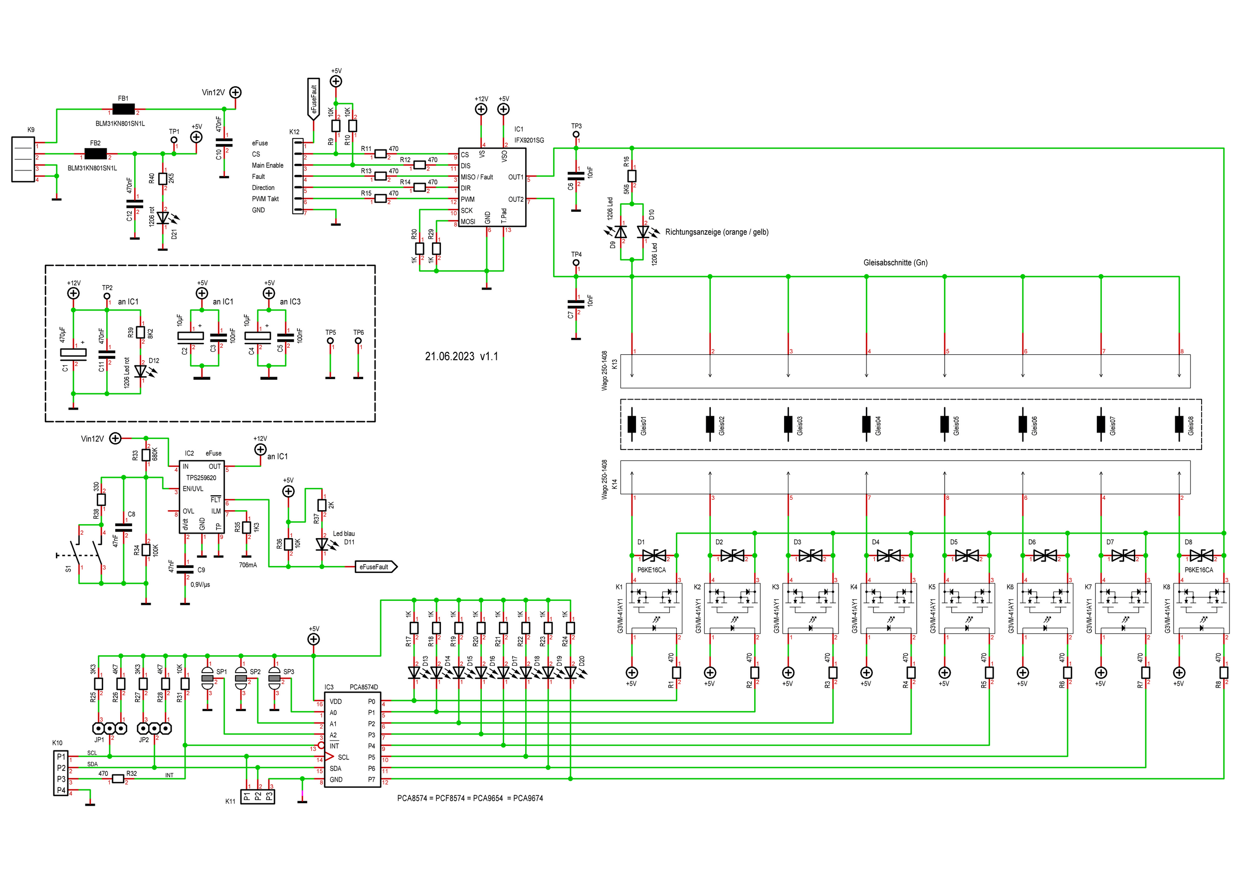
Elektronischer Schaltplan mit Leistungsteil und PCA8574 I2C-Erweiterer
Vin12V, K6, BLM31PG101SL, F5, C2, C3, R11, R12, R13, R14, R15, R17, IC3, MISO, Fault, Out1, Out2, GND, +5V, +12V, C5, C6, C7, C8, C9, C10, C11, C12, C13, C14, C15, C16, C17, C18, C19, C20, C21, C22, C23, C24, C25, C26, C27, C28, C29, C30, C31, C32, C33, C34, C35, C36, C37, C38, C39, C40, C41, C42, C43, C44, C45, C46, C47, C48, C49, C50, C51, C52, C53, C54, C55, C56, C57, C58, C59, C60, C61, C62, C63, C64, C65, C66, C67, C68, C69, C70, C71, C72, C73, C74, C75, C76, C77, C78, C79, C80, C81, C82, C83, C84, C85, C86, C87, C88, C89, C90, C91, C92, C93, C94, C95, C96, C97, C98, C99, C100, C101, C102,
in „Schaltung so funktional? MosFET Modellbahn“ · Analoge Elektronik und Schaltungstechnik · · Schaltpläne
-
PDF
PCA8574-rev03.pdf
PCA8574; PCA8574A Remote 8-bit I/O expander for I C-bus with interrupt Rev. 3 — 3 June 2013 Product data sheet 1. General description The PCA8574/74A provides general-purpose remote I/O expansion via the
in „NXP PCA8574 hat Phänomen mit 2 Adressen“ · Mikrocontroller und Digitale Elektronik ·
-
PDF
PCA8574-rev02.pdf
number Topside Package mark Name Description Version PCA8574D PCA8574D SO16 plastic small outline package; 16 leads; body width 7.5 mSOT162-1 PCA8574AD PCA8574AD PCA8574N PCA8574N DIP16 plastic dual in-line package; 16 leads (300 mil); long boSOT38-1 PCA8574AN PCA8574AN PCA8574PW PCA8574 TSSOP16 plastic thin shrink small outline package; 16 leads; SOT403-1 body width 4.4 mm PCA8574APW PA8574A PCA8574TS PCA8574 SSOP20 plastic shrink small outline package; 20 leads
in „NXP PCA8574 hat Phänomen mit 2 Adressen“ · Mikrocontroller und Digitale Elektronik ·
-
Datei
i2c_test.c
(PCF8574_I2C_ADR)) { PORTC |= (1<<PC5); // error while(1); // stop } // PCA9536 P0-P2 auf OUTPUT umstellen, P3 Input PCA9536_Write(PCA9536_I2C_ADR, PCA9536_CONFIG_REG, 0x08); while(1) { // Hauptschleife PCF8574
in „Denkfehler mit PCA9536 (Problem)“ · Mikrocontroller und Digitale Elektronik ·
-
Datei
i2c_test.c
(PCF8574_I2C_ADR)) { PORTC |= (1<<PC5); // error while(1); // stop } // PCA9536 P0-P2 auf OUTPUT umstellen, P3 Input PCA9536_Write(PCA9536_I2C_ADR, PCA9536_CONFIG_REG, 0x08); while(1) { // Hauptschleife PCF8574
in „Denkfehler mit PCA9536 (Problem)“ · Mikrocontroller und Digitale Elektronik ·
-
Datei
Compiling.txt
library "AVRxDB_TCAn" Compiling library "TypeTraits" Compiling library "MyToolbox" Compiling library "MyPCA8574" Zuvor kompilierte Datei wird verwendet: C:\Users\Worker\AppData\Local\Temp\arduino_build_389122\libraries\MyPCA8574\MyPCA8574.cpp.o Compiling library "MyPCF8574" Zuvor kompilierte Datei wird verwendet
in „BFD DWARF Error - avr-gcc 13.2 & binutils 2.41“ · Mikrocontroller und Digitale Elektronik ·
-
Datei
Programm_Option_-Wl-v_Ausgabe_.txt
Worker\\AppData\\Local\\Temp\\arduino_build_164294\\sketch\\Modellbahn_TestEncoderInterfacePCF8575_PCA9685_FRAM_016.ino.cpp" -o nul Alternatives for MyPCA8574.h: [MyPCA8574@0.1.0] ResolveLibrary(MyPCA8574.h) -> candidates: [MyPCA8574@0.1.0] "C:\\avrToolchain\\avr-gcc-8.5.0_mingw32_binutils2.42_avrLibc2.2GitHub
in „GCC v14 Release“ · Mikrocontroller und Digitale Elektronik ·
-
PDF
I2C-Bus_Adressliste__Elektronik-Magazin.pdf
page/i2c-bus-adressliste-23 PCF8574 PCF8574 PCF8574 PCF8574 PCF8574 PCF8574 PCF8574 PCF8574 20.12.2010 TDA8444 TDA8444 TDA8444 TDA8444 TDA8444 TDA8444 TDA8444 TDA8444 heidi 0101 User (0) 0110 0111 PCF8576 PCF8576 PCF8577 PCF8577A PCF8578 PCF8566 PCF8566 11.10.2010 SAA1064 SAA1064 SAA1064 SAA1064 PCF8579 PCF8574A PCF8574A PCF8574A PCF8574A PCF8574A PCF8574A PCF8574A peterjo 1000 TEA6320 TDA8424 TDA8425 User (0) TEA6330 TDA8425 TDA8415 TDA8426 TDA8416 TDA8420 TDA8420 TDA8440 TDA8421 TDA8421 TDA8940 31.08.2010
in „PCF8574/PCF8574A Adressierung“ · Mikrocontroller und Digitale Elektronik ·
-
PDF
Elektronik_Sortimente.pdf
and calendar with 240 x 8-bit RAM (PCF8583) 5-10x 16-channel, 12-bit PWM Fm+ I2C-bus LED controller (PCA9685) 5x 16 CHANNEL LED DRIVER WITH DOT CORRECTION AND GRAYSCALE PWM CONTROL (TLC5940NT) 5x 8-bit I/O expander for I2C-bus (PCF8574, PCA8574, PCA8574A) 5x 16-Bit I/O Expander with Serial Interface (MCP23017
in „Einkaufsliste für die Einrichtung eines Elektronik-Labors“ · Mikrocontroller und Digitale Elektronik ·
-
PDF
AVR_Roboter_Dokumentation.pdf
Technology Infrastructure, Lab Service, Lehrer Workshop Januar 2009 I²C Adresstabelle Motoransteuerung PCA9533D01 0xC4 oder PCA9533D02 0xC6 Speichererweiterung EEPROM 24C64 0xA0 Uhr PCF2128 0xA2 RC5 Fernbedienung PCA8574AN 0x38 oder PCA8574 0x40 Shared Technology Infrastructure, Lab Service, Lehrer Workshop
in „Anfängerprobleme“ · Mikrocontroller und Digitale Elektronik ·
-
Datei
HBRIDGE.h
/* Platine mit H-Bridge IFX9201SG und PCA8574D */ #pragma once #include <MyPCA8574.h> #include <AVRxDB_Pin.h> #include <AVRxDB_TCAn_FreqGen.h> class HBridge { private: OutputPin <pinPB0> pwmTakt; // PB0 TCA1 WO0 OutputPin <pinPB1> direction
in „Cast "verstecken" wenn möglich?“ · Mikrocontroller und Digitale Elektronik ·
-
Datei
i2c.h
/////////////////////////////////////////////////////////////////////////////////////////////// // PCA9554 (Remote 8-bit I/O expander) /////////////////////////////////////////////////////////////////////////////////////////////////// #define I2C_ADDR_PCA9554 0x20 // 00100AAA #define PCA9554_CMD_INPUT 0x00 #define PCA9554_CMD_OUTPUT 0x01 #define PCA9554_CMD_POLARITY 0x02 #define PCA9554_CMD_CONFIG 0x03 #define CHANNEL_1 0x01 #define CHANNEL_2 0x02 #define CHANNEL_3 0x04 #define CHANNEL_4 0x08 #define RING_E1 0x10
in „MSP430F2370 I2C“ · Mikrocontroller und Digitale Elektronik ·
-
Datei
i2c.h
/////////////////////////////////////////////////////////////////////////////////////////////// // PCA9554 (Remote 8-bit I/O expander) /////////////////////////////////////////////////////////////////////////////////////////////////// #define I2C_ADDR_PCA9554 0x20 // 00100AAA #define PCA9554_CMD_INPUT 0x00 #define PCA9554_CMD_OUTPUT 0x01 #define PCA9554_CMD_POLARITY 0x02 #define PCA9554_CMD_CONFIG 0x03 #define CHANNEL_1 0x01 #define CHANNEL_2 0x02 #define CHANNEL_3 0x04 #define CHANNEL_4 0x08 #define RING_E1 0x10
in „I2C Ansteuerung von PCA9685 mit MSP430“ · Mikrocontroller und Digitale Elektronik ·
-
Datei
I2C_TWI0_Address_and_Frequency_Scanner.ino
Address Scanning... 7Bit 7Bit 8Bit I2C device found at address 0x26 = B0010.0110 = B0100.110x ... U6: PCA8574D (Portexpander) I2C device found at address 0x48 = B0100.1000 = B1001.000x ... U8: TMP101 I2C device found at address 0x50 = B0101.0000 = B1010.000x ... U9: FM24W256 (256K FRAM) I2C device found
in „NXP PCA8574 hat Phänomen mit 2 Adressen“ · Mikrocontroller und Digitale Elektronik ·
-
Datei
i2c.c
///////////////////////////////////////////////////////////////////////////////////// /*! * \brief PCA9554 initialisieren. * \return TRUE bei Erfolg, FALSE bei Fehler */ unsigned char init_PCA9554 (void) { unsigned char data[2]; // Befehl bauen data[0] = PCA9554_CMD_OUTPUT; data[1] = 0x00; // Ausgaenge alle low if (!i2c_write_bytes(I2C_ADDR_PCA9554, 2, &data[0])) return FALSE; // Befehl bauen data[0] = PCA9554_CMD_CONFIG; data[1] = 0x00; // Alles Output if (!i2c_write_bytes(I2C_ADDR_PCA9554, 2, &data[0])) return FALSE; return TRUE; } /////
in „MSP430F2370 I2C“ · Mikrocontroller und Digitale Elektronik ·
-
Datei
i2c.c
///////////////////////////////////////////////////////////////////////////////////// /*! * \brief PCA9554 initialisieren. * \return TRUE bei Erfolg, FALSE bei Fehler */ unsigned char init_PCA9554 (void) { unsigned char data[2]; // Befehl bauen data[0] = PCA9554_CMD_OUTPUT; data[1] = 0x00; // Ausgaenge alle low if (!i2c_write_bytes(I2C_ADDR_PCA9554, 2, &data[0])) return FALSE; // Befehl bauen data[0] = PCA9554_CMD_CONFIG; data[1] = 0x00; // Alles Output if (!i2c_write_bytes(I2C_ADDR_PCA9554, 2, &data[0])) return FALSE; return TRUE; } /////
in „I2C Ansteuerung von PCA9685 mit MSP430“ · Mikrocontroller und Digitale Elektronik ·
-
PDF
I2CselectionGUIDE.pdf
TDA9177 YUV transient improvement processor 0 0 0 TDA9178 YUV transient improvement processor 0 0 A0 PCA1070 Programmable speech transmission IC 0 A1 A0 PCF8575 Remote 16-bit I/O expander 0 A1 A0 PCF8575C Remote 16-bit I/O expander 0 A1 A0 SAA1300 Tuner switch circuit A2 A1 A0 TDA8444 Octuple 6-bit DAC A2 A1 A0 PCF8574 8-bit remote I/O port (I C-bus to parallel converter) 1 0 A0 PCD3311C DTMF/modem/musical tone generator 1 0 A0 PCD3312C DTMF/modem/musical tone generator 1 1 1 PCD5002 Pager decoder 1999 Aug 24 16 Philips
in „Übersicht I2C-Adressen“ · Mikrocontroller und Digitale Elektronik ·
-
PDF
AN10216.pdf
Sub • system energy Interrupt address Slide 121 decoder conservation • time and date stamp The PCF8574 and PCA8575 are well known general for point of sales terminals or bank purpose I/O expanders. The PCA9500 is a combination DesignCon 2003 TecForum I C Bus Overview machines 119 of the PCF8574 with
in „AVR TWI: Hängt nach dem Flaschen“ · Mikrocontroller und Digitale Elektronik ·
-
PDF
notes_82b96.pdf
to either one (or none) of the outgoing busses. Philips Semiconductors Which Buffer ?? Application PCA9515 PCA9516 P82B96 P82B715 Data sheet supply voltage range Vcc 3.0 – 3.6 V 3.0 – 3.6 V 2 – 15 V 4.5 – 12 V Nominal logic levels supported (range) Vcc to 5.5 V Vcc to 5.5 V Vcc to 15 V Equal/less than
in „18 x SHT11 an welchem Mikrocontroller“ · Mikrocontroller und Digitale Elektronik ·
-
PDF
notes_82b96.pdf
to either one (or none) of the outgoing busses. Philips Semiconductors Which Buffer ?? Application PCA9515 PCA9516 P82B96 P82B715 Data sheet supply voltage range Vcc 3.0 – 3.6 V 3.0 – 3.6 V 2 – 15 V 4.5 – 12 V Nominal logic levels supported (range) Vcc to 5.5 V Vcc to 5.5 V Vcc to 15 V Equal/less than
in „I²C galvanisch trennen“ · Mikrocontroller und Digitale Elektronik ·
-
PDF
PCA9533.pdf
LED on and off as is currently done when using normal I/O expanders like the NXP Semiconductors PCF8574 or PCA9554. Any bits not used for controlling the LEDs can be used for General Purpose parallel Input/Output (GPIO) expansion, which provides a simple solution when additional I/O is needed for ACPI
in „[V] 20St 4-Bit I2C LED PWN Treiber NXP PCA9533 (SO8) (1€/St)“ · Markt ·
-
PDF
PCA9533.pdf
LED on and off as is currently done when using normal I/O expanders like the NXP Semiconductors PCF8574 or PCA9554. Any bits not used for controlling the LEDs can be used for General Purpose parallel Input/Output (GPIO) expansion, which provides a simple solution when additional I/O is needed for ACPI
in „[V] einige 4 Bit I2C LED PWN Treiber NXP PCA9533 (SO8)“ · Markt ·
-
PDF
PCA9533.pdf
LED on and off as is currently done when using normal I/O expanders like the NXP Semiconductors PCF8574 or PCA9554. Any bits not used for controlling the LEDs can be used for General Purpose parallel Input/Output (GPIO) expansion, which provides a simple solution when additional I/O is needed for ACPI
in „[V] 4-Bit I2C LED PWN Treiber NXP PCA9533 (TSSOP-8) (1€/St)“ · Markt ·
-
PDF
PCA9533.pdf
LED on and off as is currently done when using normal I/O expanders like the NXP Semiconductors PCF8574 or PCA9554. Any bits not used for controlling the LEDs can be used for General Purpose parallel Input/Output (GPIO) expansion, which provides a simple solution when additional I/O is needed for ACPI
in „[V] 4-Bit I2C LED PWN Treiber NXP PCA9533 (TSSOP-8) (12€ / 20St)“ · Markt ·
-
PDF
PCA9533.pdf
LED on and off as is currently done when using normal I/O expanders like the NXP Semiconductors PCF8574 or PCA9554. Any bits not used for controlling the LEDs can be used for General Purpose parallel Input/Output (GPIO) expansion, which provides a simple solution when additional I/O is needed for ACPI
in „[V] nochmal 4-Bit I2C LED PWN Treiber NXP PCA9533 (TSSOP-8) (12€ / 20St)“ · Markt ·
-
PDF
PCA9533.pdf
LED on and off as is currently done when using normal I/O expanders like the NXP Semiconductors PCF8574 or PCA9554. Any bits not used for controlling the LEDs can be used for General Purpose parallel Input/Output (GPIO) expansion, which provides a simple solution when additional I/O is needed for ACPI
in „[V] 4-Bit I2C LED PWN Treiber NXP PCA9533 (TSSOP-8) (12€ / 20St)“ · Markt ·
-
PDF
PCA9533.pdf
LED on and off as is currently done when using normal I/O expanders like the NXP Semiconductors PCF8574 or PCA9554. Any bits not used for controlling the LEDs can be used for General Purpose parallel Input/Output (GPIO) expansion, which provides a simple solution when additional I/O is needed for ACPI
in „[V] 4-Bit I2C LED PWN Treiber NXP PCA9533 (TSSOP-8) (30St/17€)“ · Markt ·
-
PDF
PCA9533.pdf
LED on and off as is currently done when using normal I/O expanders like the NXP Semiconductors PCF8574 or PCA9554. Any bits not used for controlling the LEDs can be used for General Purpose parallel Input/Output (GPIO) expansion, which provides a simple solution when additional I/O is needed for ACPI
in „[V] 4-Bit I2C LED PWN Treiber NXP PCA9533 (TSSOP-8) (30St/12€)“ · Markt ·
-
PDF
PCA9533.pdf
LED on and off as is currently done when using normal I/O expanders like the NXP Semiconductors PCF8574 or PCA9554. Any bits not used for controlling the LEDs can be used for General Purpose parallel Input/Output (GPIO) expansion, which provides a simple solution when additional I/O is needed for ACPI
in „[V] 4-Bit I2C LED PWN Treiber NXP PCA9533 (TSSOP-8) (30St/12€)“ · Markt ·
-
PDF
PCA9531_5-181573.pdf
LED on and off as is currently done when using normal I/O expanders like the NXP Semiconductors PCF8574 or PCA9554. Any bits not used for controlling the LEDs can be used for General Purpose parallel Input/Output (GPIO) expansion, which provides a simple solution when additional I/O is needed for ACPI
in „[V] 3St. SMD 8-bit I2C LED Treiber NXP PCA9531D (SO16)“ · Markt ·
-
PDF
I2C_Sheet.pdf
VCC VCC VCC VCC VCC VCC zum Controller 6 C50 USER TWI LEDS 1 0u1 R70 R71 R72 R73 PA3 R32 R33 VCC U6 PCA8574 2K7 2K7 4K7 4K7 PA2 0100 A2 A1 A0 LEDS B7-B0 3K3 3K3 c TWI-0 1K R26 LED8 LED7- 12 V 15 A2 A1 A0 1K R25 LED7 LED6- 11 P7 SDA 14 4 2 4 2 SCL_BUS 3 JP11 4 2 JP12 1 J39 TWI-0 0 0 0 0x20 1K R24 LED6
in „NXP PCA8574 hat Phänomen mit 2 Adressen“ · Mikrocontroller und Digitale Elektronik ·
-
PDF
Ausgangsstufen_Logic_IC.pdf
aufgenommen werden. Bei HIGH können nur sehr geringe Ströme entnommen werden, siehe Port-Expander PCF8574. Der Widerstandswertes des Pull-up-Widerstands darf nicht zu groß gewählt werden, da sonst zusammen mit Eingangs- und parasitären Kapazitäten die Signale verschleifen und im Extremfall nicht mehr korrekt
in „Wittig(welec) DSO W20xxA Open Source Firmware (Teil3)“ · Mikrocontroller und Digitale Elektronik ·
-
PDF
AN255_I2C__SMBus_REPEATERS_HUBS_AND_EXPANDERS.pdf
INTEGRATED CIRCUITS APPLICATION NOTE AN255-02 I²C / SMBus REPEATERS, HUBS AND EXPANDERS PCA9511, PCA9512, PCA9513, PCA9514, PCA9515, PCA9516, PCA9518, P82B96, P82B715 that discusses device operation, maximum cable length and frequency calculations and typical applications.te Phil Tracy – Senior
in „SPI oder TWI“ · Mikrocontroller und Digitale Elektronik ·
-
PDF
AN255.pdf
INTEGRATED CIRCUITS APPLICATION NOTE AN255-02 I²C / SMBus REPEATERS, HUBS AND EXPANDERS PCA9511, PCA9512, PCA9513, PCA9514, PCA9515, PCA9516, PCA9518, P82B96, P82B715 that discusses device operation, maximum cable length and frequency calculations and typical applications.te Phil Tracy – Senior
in „50 X LM75 an ATMEGA16?“ · Mikrocontroller und Digitale Elektronik ·
-
PDF
AVRnDxBoard.pdf
SCL 2 2 3 3K3 3K3 3K3 3K3 BSS138 BSS138 VDD OUT JP18 R42 R43 4 SDA U3 2 4 2 4 C 1 3K3 3K3 VCC C I2C PCA8574 1 JP12 JP13 V5V/3V3 SEL 2 C17 100n 1 3 1 3 3 1K R24 D13 C 12 P7 V A0 1 1K R23 D12 11 2 1K R22 D11 P6 A1 10 P5 A2 3 VCC VCC VCC 1K R21 D10 9 1K R20 D9 P4 7 P3 ~{INT}3 1K R19 D8 6 R44 R45 1K R18 D7
-
Datei
Values.txt
r9 2 PWR 2 PV8251 2 PR1003 2 Power Out 2 POWER 2 PIN3F061.120 2 PIC16F877P 2 PIC16F874P 2 PG203J 2 PCA82C250 2 P6KE200A 2 OPA2333 2 OPA1632 2 OP11P 2 Netz 2 NE567 2 NE555N 2 NE5532 2 MT48LC8M16A2 2 MSTBV3 2 MOSFET-P-4D-FDC604P 2 MOC3021 2 ML10 2 MEGA8L-P 2 MEGA323-A 2 MCP41010 2 MAX3232CPE 2 MAX1626
in „[KiCad] Bibliotheksaufbau - Konzeptideen gesucht“ · Platinen ·
-
PDF
Aeternum_Sheet.pdf
I2C 3.3V - Bus A SCL/1.3A SCL/3.6B A SDA/1.3A SDA/3.6B +3V3 7 6 5 3 D1 3 IC2 SC16IS750 U$2IC$1 PCF8574P BAT43 D2 + R8 13 4 BAT43 T L A /INT P0 GPIO_0 I S D 4 VDD RESET 1 1k +3V3 P1 5 GPIO_1 8 C I O S P 1 A0 P2 6 GPIO_2 V C C 5 10 23 TX 2 7 GPIO_3 V + 1 S S 0 F 6 SDA-VSS TX 24 RX 3 A1 P3 9 GPIO_4 3 G
in „CP/M auf ATmega88“ · Mikrocontroller und Digitale Elektronik ·
-
Datei
I2COpenCm3.c
i2c_read_old(i2c_cmd_t *f_pCmd) { int rc = 0; u32 timeout = 0xFF; switch (f_pCmd->usbCmd) { case I2C_SGL://pca9548a {/* |HWADDR|*/ // apiRc = WriteFile(g_i2c_CommHandle, &f_pCmd->usbCmd, 2, &n, NULL); // if (n != 2) // { // rc = GetLastError(); // ETRACE1("ReadFile() failed with %d",rc); // rc = ERROR_I2C_READ_FAILED
in „STM32 i2c error recovery Problem“ · Mikrocontroller und Digitale Elektronik ·
-
PDF
Aeternum_V1.pdf
I2C 3.3V - Bus A SCL/1.3A SCL/3.6B A SDA/1.3A SDA/3.6B +3V3 7 6 5 D1 NOTE: Crystal speed IC9IC$1 PCF8574P BAT43 D2 $ P3 allows for common 13 4 BAT43 6 5 T L A baud rates between 18pF 18pF /INT P0 GPIO_0 I F I S D 9600 and 921600. P1 5 GPIO_1 8 C P I O S V C17 R7 C18 1 A0 P2 6 GPIO_2 Z V C C + IC8 SC16IS740
in „CP/M auf ATmega88“ · Mikrocontroller und Digitale Elektronik ·
-
Datei
Devices.txt
1X7 2 PINHD-1X2/90 2 PINHD-1X1_2.54 2 PINHD-1X12 2 PIN3F061.120 2 PIC16F877P 2 PIC16F874P 2 PG203J 2 PCA82C250 2 PC817 2 OSZILLATOR 2 OPA2333 2 OPA1632 2 OP11P 2 NPN-TRANSISTOR_SOT23W 2 -NPN-TO92-ECB 2 -NPN-TO225AA 2 NPNSOT89 2 NPNSOT323 2 N-MOSFET-SO8 2 NE567 2 NE555N 2 MYSPECIAL_CERA-DIODE 2 MTA02-156
in „[KiCad] Bibliotheksaufbau - Konzeptideen gesucht“ · Platinen ·
-
Datei
880eed3fe10373c0a5d4ca8d0892cc67.txt
I2C_DS1631_SUPPORT is not set # I2C_DS13X7_SUPPORT is not set # I2C_TSL2550_SUPPORT is not set # I2C_PCA9531_SUPPORT is not set # I2C_PCF8574X_SUPPORT is not set # I2C_MAX7311_SUPPORT is not set # I2C_UDP_SUPPORT is not set # DEBUG_I2C is not set # CAMERA_SUPPORT is not set # DC3840_SUPPORT is not set
in „Ethersex will nicht so richtig“ · Mikrocontroller und Digitale Elektronik ·
-
Datei
Configuration.h
ULTIPANEL #endif #if defined(RA_CONTROL_PANEL) #define ULTIPANEL #define NEWPANEL #define LCD_I2C_TYPE_PCA8574 #define LCD_I2C_ADDRESS 0x27 // I2C Address of the port expander #endif //I2C PANELS //#define LCD_I2C_SAINSMART_YWROBOT #ifdef LCD_I2C_SAINSMART_YWROBOT // This uses the LiquidCrystal_I2C library
-
Datei
config-mod-LK511-mt7623n-BPiR2.txt
CONFIG_I2C_ARB_GPIO_CHALLENGE=m CONFIG_I2C_MUX_GPIO=m CONFIG_I2C_MUX_GPMUX=m CONFIG_I2C_MUX_LTC4306=m CONFIG_I2C_MUX_PCA9541=m CONFIG_I2C_MUX_PCA954x=m CONFIG_I2C_MUX_PINCTRL=m CONFIG_I2C_MUX_REG=m CONFIG_I2C_DEMUX_PINCTRL=m # CONFIG_I2C_MUX_MLXCPLD is not set CONFIG_I2C_HELPER_AUTO=y CONFIG_I2C_SMBUS=m CONFIG_I2C_ALGOBIT
in „Linux Kernel 5.1.1. auf dem BPi-R2“ · PC Hard- und Software ·
-
Datei
linux-2.6.27.grasshopper.1.patch
Chip support +# +# CONFIG_DS1682 is not set +# CONFIG_SENSORS_EEPROM is not set +# CONFIG_SENSORS_PCF8574 is not set +# CONFIG_PCF8575 is not set +# CONFIG_SENSORS_PCF8591 is not set +# CONFIG_TPS65010 is not set +# CONFIG_SENSORS_MAX6875 is not set +# CONFIG_SENSORS_TSL2550 is not set +# CONFIG_I2C_DEBUG_CORE
in „AVR32 grasshopper patch für ATMEL buildroot 2.2.1“ · Mikrocontroller und Digitale Elektronik ·
-
PDF
kicad_8450_dcm_liste_neu_v3.pdf
MSP430F2955, 40pin QFN, 56KB Flash Memory, 4KB RAM nordicsemi NRF8001 BLE chip from Nordic Semiconductor nxp PCA9536D 4-bit I2C-bus and SMBus IO port, SOIC8 package PCA9536DP 4-bit I2C-bus and SMBus IO port, TSSOP8 package PCA9544AD 4-channel I2C-bus multiplexer with interrupt logic, SOIC20 package PCA9544APW
in „KiCAD Eeschema, Bibliotheksdokumentation *.dcm als PDF-Datei“ · Platinen ·
-
Datei
All.txt
SOIC8 2-wire serial EEPROM 1 IC3 SED1335F SED1335F QFP5 1 IC3 PDI-E832 PDI-E832 PDI-E832 1 IC3 PCF8574P Tastenfeld PCF8574P DIL16 I2C-Bus I/O DEVICE 1 IC3 PCA82C250 PCA82C250 DIL08 CAN CONTROLLER INTERFACE 1 IC3 OPA627P OPA627P DIL08 Difet(R) Operational Amplifiers 1 IC3 OPA2134U OPA2134U SO08 Operational
in „[KiCad] Bibliotheksaufbau - Konzeptideen gesucht“ · Platinen ·
-
PDF
311_Schaltungen.pdf
kompati- Den Kern der Schaltungen bildet der bles LCD und eine Ziffern-Tastatur ver- I/O-Expander PCF8574 [1] (Hinweis, es wenden den I2C-Bus, der nur zwei Port- gibt den PCF8574 in zwei funktionsglei- pins des Controllers belegt – SCL und chen Versionen, die einen unterschiedli- SDA. Beide Schaltungen
in „[S] Sammlung von elektr. Schaltungen“ · Mikrocontroller und Digitale Elektronik ·