Video Input Level – – 1.5 V D CVBS Video Input Current – 50 200 nA A Peak White Clip (Note 1) 108 112 116 % B Video Input Impedance Measured at 1.0 kHz (at Pin 13) – 500/4 – k /pF D Video S/N – Figure 6 Figure 6 dB C See Note 2 Differential Phase Figure 7 Figure 7 Figure 7 ⋅ C Differentical Gain On
157.0277ms prompt eval count: 17 token(s) prompt eval duration: 151.5652ms prompt eval rate: 112.16 tokens/s eval count: 11 token(s) eval duration: 201.5275ms eval rate: 54.58 tokens/s Bei den Wiederholungen gab es: Hello again! How are you doing? 😊 total
gerade darueber nach 400Euro fuer eine RX9060 mit 16Gig rauszuhauen. In dem Zusammenhang mal einen Tip. Ich habe aktuell eine 7-8Jahre alte RX550 mit 8GB Vram. Mein Rechner lief immer bombenstabil! Aber mit den KIs ist er gerne mal voll brutal mit merkwuerdig blinkenden Grafikbildschirm verreckt wenn
isprovided by R101//C106, C10,, C108 switched by relay K101; — x200 attenuationby R101//C109,C110,C111, C112,C113,switched .y relayK102; The preset capacity trimmers allow calibration ofthe different ranges. R A N G EATTENUATION AC INPUT R A RELAY 220Vv 2 110VV (RNGA) 20 V 20 1 Vv K101 ReA , . 200 V 200 1
Pin 16) 0 – –10 mA Sync, Blanking Level (DC level between pulses, see Figure 9e) 1.7 – 8.2 Vdc Sync Tip Level (see Figure 9e) –0.5 0 0.9 Sync Pulse Width (see Figure 9e) 2.5 – 5.2 s R, G, B Input (Amplitude) – 1.0 – V pp R, G, B Peak Levels for DC Coupled Inputs, with Respect to Ground 2.2 – 4.4 V Chrominance
1-390172-4 c , center barb .112 .365 e A Standard, with 3.18 10.92 s , center barb .125 .430 390175-5 c Standard, with 1.96 9.27 i center barb .077 .365 1-390175-5 n r Scenter barbth .112 .280 2-390175-5 n Sync DRAM a Reverse, with
directly on to avoid parallax errors and use a small blunt pointed scribe, such as a pencil eraser tip, to produce the best accuracy for the calibration. Touch the screen directly over the first dot. The dot in the next corner then lights. Touch the second dot, then the third dot to finish the calibration
O EC H/W blinking 120 WR# SPI_SI O 38 CLKRUN# N.C O Reserved 93 GPIO55 SCRL_LED# O EC H/W controls 112 XCLKI 32KXCLKI I 39 KSO0 KSO0 O For Keyboard interface 95 GPIO56 PWR4G_SW# I * 123 XCLKO 32KXCLKO O 40 KSO1 KSO1 O For Keyboard interface 97 GPXOA00 SPI_MODE# O "HW Strap for SPI Flash d124 V18R K_V18R
Der Analysator war mehrere Monate im Standby, hat davor aber perfekt funktioniert. Hat jemand einen Tip, wo ich die Fehlersuche beginnen sollte? Betriebsspannung? EEPROM/gepuffertes RAM? Oder etwas ganz anderes? Jochen DH6FAZ
> Option 010 Rack Mount Slide Kit. > [...] the weight of the > HP 8566B, approximately 50 kg > (112 lb), the use of this option > is recommended. Oha 🤣 Heb' dir keinen Bruch! mfg mf
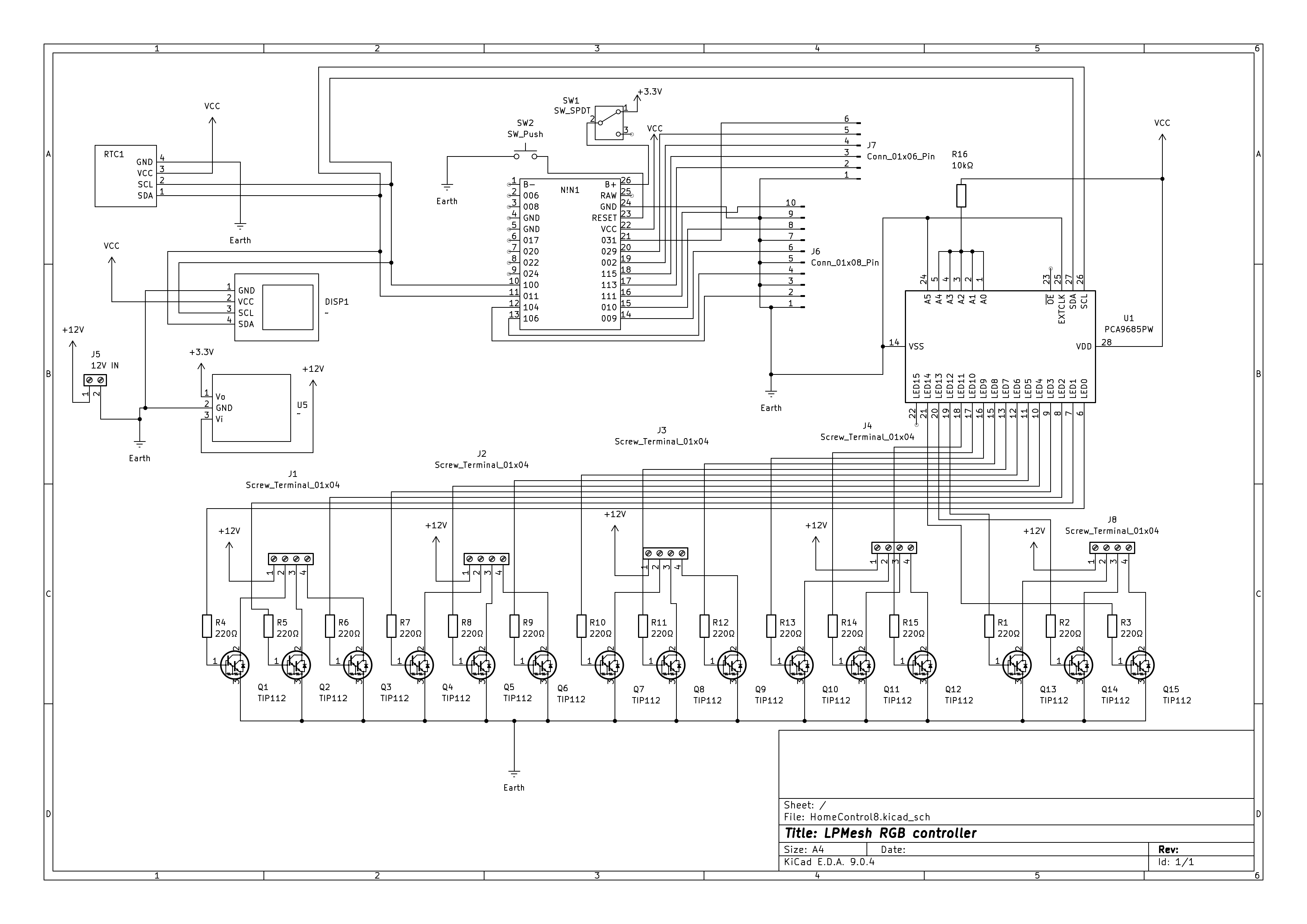
machen kann, aber da hört es aber auch auf. Kurz zur Schaltung: ein PCA9685 (VCC 3,3V) schaltet qua TIP112-Transistoren die 12V der LED-Strips; ich rechne nicht mit Strömen >0,5A. Der PCA9685 kann pro Kanal 25mA liefern, da sollten die 220Ohm bei 3,3V eigentlich passen. Die PWM-Frequenz würde ich
Danke erstmal - das ein MOSFET sinnvoller ist, ist mir bekannt; ich hatte damals die TIP112 genommen, weil ich so ca. 64 Stück brauchte, und AliExpress noch kein Ding war... und die alternativen MOSFETs hätten damals an die 100€ gekostet. Ein Preisbereich bis sagen wir mal 0,40€ pro
! • To remove the Wireless LAN Antenna Connector, use the special MHF Connector Remover. Hook the tip of this tool on the cover of the Wireless LAN Antenna Connector and pull it straight in the direction of the engaging axis of the Wireless LAN Black Antenna Connector. ࠇ Special removing tool CABLE
recipientul colector pentru praf, > „Golirea nuată de aspirare (fig. 10/ 3 ). 3 Apăsaţi butonul periei tip tambur, pentru a conecta şi deconecta pe- recipientului colector pentru praf”la pagina 124. ria tip tambur (fig. 10/ 2 ). 4 Aspiraţi. 2 Rotiţi capacul filtrului în sens contrar acelor de ceas (fig.
atmosphere, do not allow flux to enter inside. ▼ Manual soldering ☉Raise the temperature of the soldering tip between 260 and 300°C/500 and 572°F (30 W) and solder within 5 seconds. ☉The sensor output may vary if the load is applied on the terminal during soldering. ☉Keep the soldering tip clean. ▼DIP soldering
atmosphere, do not allow flux to enter inside. ▼ Manual soldering ☉Raise the temperature of the soldering tip between 260 and 300°C/500 and 572°F (30 W) and solder within 5 seconds. ☉The sensor output may vary if the load is applied on the terminal during soldering. ☉Keep the soldering tip clean. ▼DIP soldering
einen Einzelpreis von DM 26,- in Erinnerung. Ich habe hier noch einen alten Halbleiter-Katalog Nr. 112 von Strixner & Holzinger. Der muss so von ca. 1990 sein. Darin ist der µA726 mit DM 88,92,- gelistet.
und funktioniert trotzdem" Tastatur: richtig teuer, und zu schmal. Löter: damals hatte man Ersa Tip 260, 16W Damit spielen: höchstens 6 Monate dann war man ihn leid :-) Diese Doppeltransistoren mit schönem Gleichlauf waren damals wegen der üblichen Herstelltoleranzen gut selektierte Dinge und
terminated with a banana plug with retractable sheath on each end. Model 8606 High Performance Probe Tip Kit: Consists of two spade lugs, two alligator clips, and two spring hook test probes. (The spade lugs and alligator clips are rated at 30V RMS, 42.4V peak; the test probes are rated at 1000V.) These
Gate Control Bit Access Symbol Description [7] R/W Agc_gate_vsync_coarse This bit forces coarse sync-tip and backporch gates to be used during vsync when VCRs are detected Default = 1. [6] R/W Agc_gate_vsync_stip This bit forces sync-tip clamping during vsync. Default = 0. [5:4] R/W Agc_gate_kill_mode These bits determine the method that sync-tip and backporch gates are suppressed: 00 = off 01 = enabled – if sync-tip gate is killed, kill backporch gate 10 = enabled – if sync-tip gate is killed, kill backporch gate, 资料收藏: except during vsync
Wir (ich) kann aber nicht in deinen Kopf schauen... Wenn ja (freiwillige Feuerwehr): Mit der 112 erreicht man immer nur allgemeine Leitstellen, welche sich für solche Anfragen "bedanken" werden, nicht jeder lebt im Örtchen, wo eine freiwillige Feuerwehr mit dazu gehört usw. Details und Namen
die örtliche Freiwillige Feuerwehr meinst? Wer lesen kann (siehe PS) ist klar im Vorteil. Die 112 ist eine NOTRUF-Nummer! Über die ILS kann eine Türöffnung (z.B. Kleinkind eingeschlossen) angefordert werden. Jedoch kommt da neben FW, POL auch ein RTW. Sowie im Nachgang eine fette Rechnung.
Call Subroutine (Address xxxx) > 0A 0x xx x0 -> Jump always (Address xxxx) > [/code] Sehr guter Tip! Nach sowas habe ich gesucht. Demnach stimmt etwas an meinem Disassembler (Aufruf?) nicht: [code] 0124 0x08200000 NOP 0280 0x0a200720 .word 0x0a200720 0334 0x0a000bf0 .word 0x0a000bf0 [/code
exakt auf OMAP_ABE_STACK_ADDR [code] 0000: 1600200f const 0x0200,r15 # OMAP_ABE_STACK_ADDR[112] 0004: 0a000910 jmp 0x0244 [/code] Weitere solche im Code verstreute ld-Befehle laden die Adressen von anderen Parametern aus abe_dm_linux.h und machen anschließend einen unidentifizierten Befehl
> Ich bin total begeistert von diesem Setup, das Löten auch von Bauteilen Noch ein Tip. Es lohnt sich da unten vor das Objektiv einen UV-Filter vor zu schrauben. Nicht weil man UV-Filter braucht, aber das ist die billigste Art eine Glasscheibe zu bekommen die man abschrauben kann um da
vision-objektiv-meo-006sl-fuer-mantis-elite-6x-slwd.html Das "slwd" steht für "Super Long Working Distance", hier 112 mm.
Beitrag #7782207: > Ich würde sagen, ändere einfach den Partitionstyp. Das ist der schlechteste Tip den man geben kann. Änderungen an der Partitionstabelle macht man nur wenn man weis man tut und da wäre ich mir bei alv nicht so sicher. Wenn das dumm läuft ist am Ende die komplette Partitionstabelle
Windof-Platte ist. Steht im Sektor 1 (2. Sektor der HDD): Sektor 1 (Parent: WDC WD3200BEKT-60V5T112.01A12 Datensatz: 64) 202: 4E 00 54 00 4C 00 - 44 00 52 00 N.T.L.D.R. dann ist es warscheinlich eine Windows Partition.
G. K. schrieb im Beitrag #7784203: > klare Wahlempfehlung 112
H. H. schrieb im Beitrag #7784216: > G. K. schrieb: >> klare Wahlempfehlung > > 112 112? Wie langweilige! Ruf doch besser 0190-994996 oder 0190-988098 an!
fully charged at the end of the automatic mode. Loop filling: support, 1-9 cycles adjustable Status Tip: Support Stop discharge voltage: 2.5V, 2.6V, 2.7V, 2.8V, 2.9V, 3.0V, 3.1V, 3.2V, 11 adjustable 3.3V, 3.4V, 3.5V Discharge current: max. 1Acurrent, not adjustable, does not support self-improvement Cooling
perform the following operations: • Press SIM card holder ejector with a sharp object (for example, the tip of a pen). • Insert the SIM card in the holder. • Verify the SIM card fits in the holder properly. • Insert the holder in the M1306B. • Connect the antenna to the SMA connector. • Connect both sides
foil, to prevent electrostatic charge build-up or exposure of the assembly. 3. Use only a grounded-tip soldering iron to solder or unsolder ES devices. 4. Use only an anti-static solder removal device. Some solder removal devices not classified as "anti-static" can generate electrical charges sufficient
der Broschüre Schal tungen sowjetischer ·und tschechoslowakischer Transistorrund funkgeräte (Band 112 der Reihe electronica)beschrieben. 10 2. Reiseempfänger 2.1. Almas (AJIMA3) Der Reiseempfänger Almas ist für die BereichM und L aus gelegt. Die Empfindlichkeit wird mit 0,6 . .. 1,5 mVjm im Mittelwellenbereich
Nimm doch erstmal die billigen Wattestäbchen a la Q-Tip und stochere/reibe den Russ weg, ohne jeden Einsatz von Chemie. Dabei sieht/spürt man schon, welche Bauteile überhaupt mechanisch beschädigt sind. Im Schaltplan ist die rückseitige Klemmleiste mit
einfach eine der anderen BAW62 zum Vergleich nehmen. Im Bereich des D102 sitzen auch 2 Stück davon, V112 bzw. V115. Die sollen auch im eingebauten Zustand messbar sein. Einfach mit dem Multimeter im Diodentest messen. Der Minusanschluss des Messgerätes liegt an der Kathode, wenn die Diode in Durchlassrichtung
Gehäuse EHSOP5 aber nur vier Pins auf einer Seite https://www.silan.com.c n/en/index.php/product/index/112.html die Lücke in c n entfernen, "könnte Spam enthalten" Tausendfüssler mit Holzbein, ein Pin weggelassen: https://datasheet.lcsc.com/lcsc/2209161700_Hangzhou-Silan-Microelectronics-SD6822STR_C601587
%22+%226+drain%22+%227+gnd%22+filetype:pdf+site:datasheet.lcsc.com Danke an Matthias S. für den Tip mit den 1,5 Ohm, damit fand ich heraus, dass das Pin 3 CS (Current Sense) heißen muss. Benjamin, wie heißt die Paulmann-Lampe genau? Wo gekauft?
strobe (sheet 3, TDS 520B Mod CM Component Service Manual 1–7 Detailed Circuit Description JP1400, pin 112 and sheet 5, JP1200, pin 112) is strobed to latch the gain and bandwidth bits into Ch1 and Ch3. This strobe pin comes from sheet 21, U1050, pin 17. Next, 16 more bits are shifted in and again only the
teilweise muss man sogar mehrere Lötstellen öffnen, um an das MainBoard ran zu kommen (Manual ab PDF-Seite 112)
#7602264: > bezog ich mich natürlich jaja, was hat das immer noch mit dem Titel zu tun? Der Tip mit dem Magnetkabel ist nicht per se schlecht bloß hier absolut falsch.
foil, to prevent electrostatic charge buildup or exposure of the assembly. 3. Use only a grounded-tip soldering iron to solder or unsolder ES devices. 4. Use only an anti-static solder removal device. Some solder removal devices not classified as [anti-static (ESD protected)] can generate electrical
Jag X61 Standard 2.5mm Audio connector for Headphone and Microphone. Signal assignment from ring to tip: GND, MIC1, HPR, HPL 3.2.5 Battery Pack X12 Connector for Li-ion or Li-polymer single cell battery. Pin# Signal Name 1 PACK+ 2 PACK+ 3 TS 4 GND 5 CELL- 6 CELL- Manufacturer: Molex Manufacturer reference

 Bild
Bild