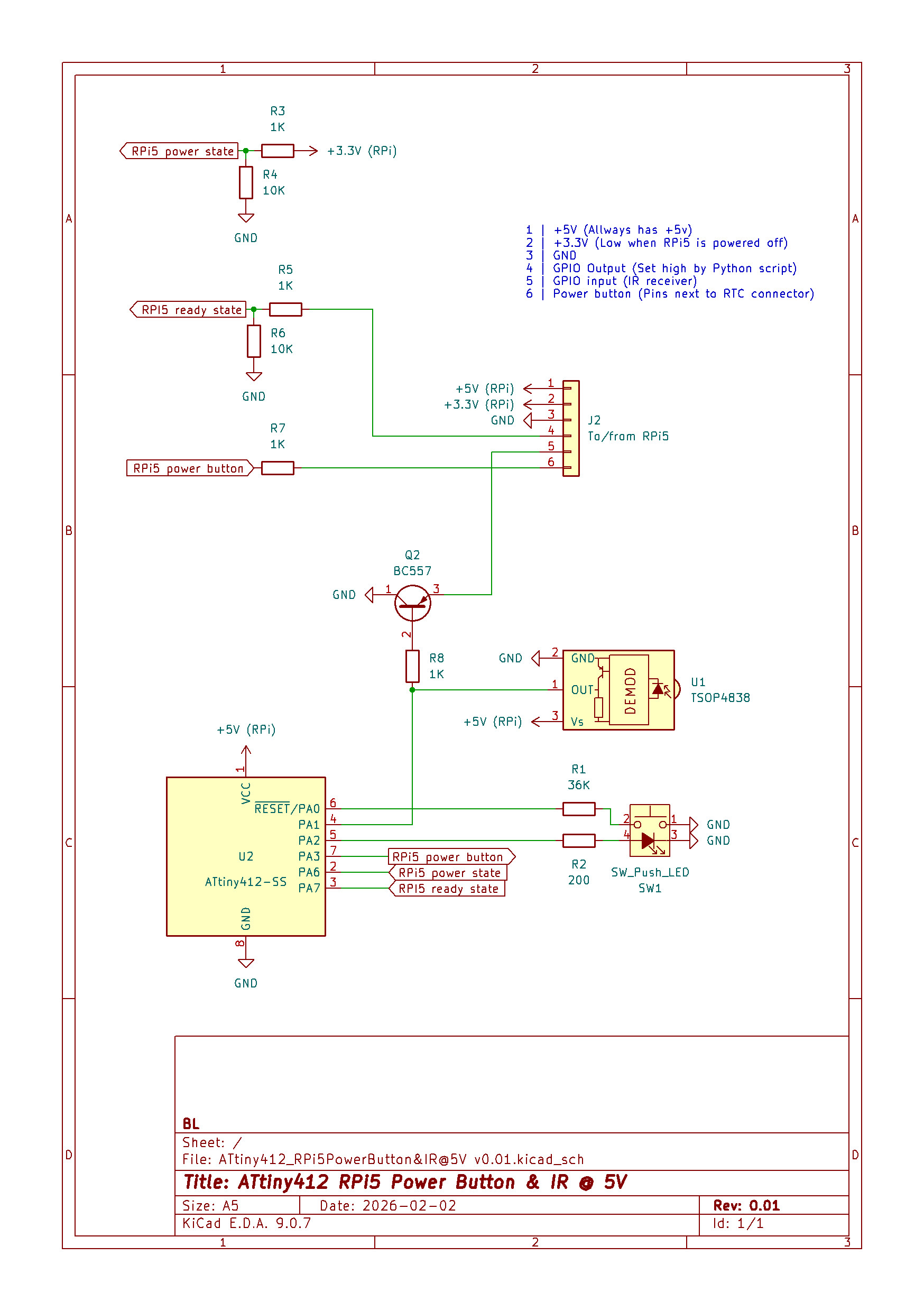
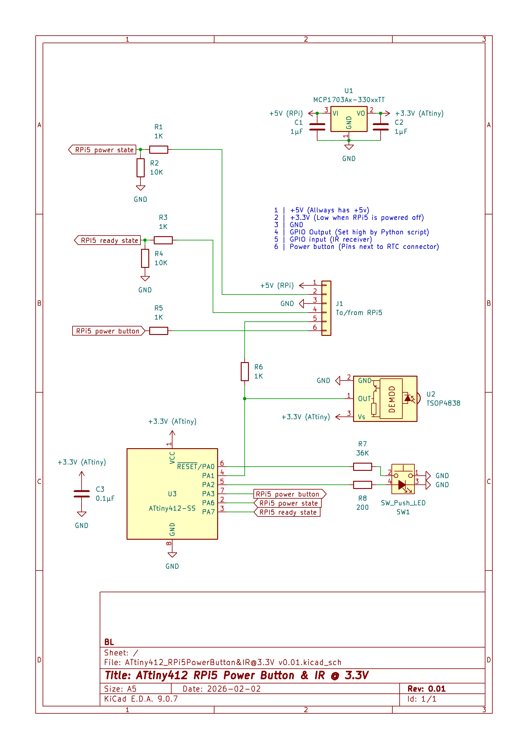
const int irLedPin = 3; // Pin für die IR-LED const int irSensorPin = 7; // Pin für den IR-Sensor (TSOP4838) IRsend irsend(irLedPin); // Erstelle ein IRsend-Objekt void setup() { Serial.begin(9600); // Serielle Kommunikation initialisieren pinMode(irSensorPin, INPUT); // Setze den Pin für den IR-Sensor
// Pin für die IR-LED definieren const int irSensorPin = 7; // Pin für den IR-Sensor (TSOP4838) void setup() { Serial.begin(9600); // Serielle Kommunikation initialisieren pinMode(irSensorPin, INPUT); // Setze den Pin für den IR-Sensor als Eingang enableIRModulation(); // Starte die 38-kHz-Modulation
unterstützt PWM-Ausgabe (wichtig für Timer) const int irSensorPin = 7; // Pin für den IR-Sensor (TSOP4838) void setup() { pinMode(irLedPin, OUTPUT); // Setze den Pin für die IR-LED als Ausgang pinMode(irSensorPin, INPUT); // Setze den Pin für den IR-Sensor als Eingang Serial.begin(9600); // Initialisiere
TSOP48.. VISHAY Vishay Semiconductors IR Receiver Modules for Remote Control Systems Description The TSOP48.. - series are miniaturized receivers for infrared remote control systems. PIN diode and preamplifier
C1 D1 10K 3 GND J2 B 100n BZX55C3V3 Ready 4 To/from RPi5 B IR-Data 5 Power-Button 6 GND U1 GND D2 TSOP4838 1N4148 3 +3.3V Vs O 1 M OUT E D GND 2 GND +3.3V +3.3V R5 1 R1 C 10K 36K C ~{RESET}/PA06 4 2 1 PA1 GND PA2 5 4 3 GND C 7 C U2 PA3 2 R2 PA6 SW_Push_LED ATtiny412-SS PA7 3 200 SW1 D N G 8 GND BL Sheet
f 901 E Seg. f 18 D E E PI 12 Seg. f to CN2 +5V R1 R2 Seg. g 109 F Seg. g 17 D1F F PI 7 Seg. g P1TSOP4838 PID401 G C C PD D1G C C G PI D 1 PItCN2NIR 200 200 PID405 DP C C PD 4 D0DP C C DP PI 9 D 2 PItCN22R P1 PR1 3 PItCN23 GND GND P0PD P6 P6 4 PItCN24 1 1 PItCN25D2 5 PItCN26D3 P0 6 PItCN27eg. a !D4
Comment Name Number 1 7-Segment U1 A-3C4G Displays Messages Or, equivalent part Remocon Sensor U2 TSOP4838 Receives RCU signal Or, equivalent part TTL U3, U4 74HCT164 Interface front board with Or, equivalent part main board Connector J1 5267-7A Front board and main board interface 7 3. Block Diagram
38kHz modulation of the IR signal and suitable receivers tuned to this frequency include the Vishay TSOP4838, Jaycar ZD1952 and Altronics Z1611A. Note that the I/O pins on the PicoMite are only 3.3V tolerant and so the receiver must be powered by a maximum of 3.3V. Sony remotes use a 40kHz modulation but
38kHz modulation of the IR signal and suitable receivers tuned to this frequency include the Vishay TSOP4838, Jaycar ZD1952 and Altronics Z1611A. Note that the I/O pins on the PicoMite are only 3.3V tolerant and so the receiver must be powered by a maximum of 3.3V. Sony remotes use a 40kHz modulation but

 Bild
Bild
 Bild
Bild