-
PDF
UDN2981.pdf
im- proved thermal characteristics. Output Voltage Range, V CE (UDN2981A, UDN2982A, The UDN2982A, UDN2982LW, A2982SLW, UDN2984A, UDN2982LW, and A2982SLW) . . 5 V to 50 V UDN2984LW, and A2984SLW drivers are also available for operation over (UDN2983A, UDN2984A, an extended
in „Treiber ICs (Datenblatt verstehen)“ · Mikrocontroller und Digitale Elektronik ·
-
PDF
2981.pdf
im- proved thermal characteristics. Output Voltage Range, V CE (UDN2981A, UDN2982A, The UDN2982A, UDN2982LW, A2982SLW, UDN2984A, UDN2982LW, and A2982SLW) . . 5 V to 50 V UDN2984LW, and A2984SLW drivers are also available for operation over (UDN2983A, UDN2984A, an extended
in „100mm 7 Segment Anzeige“ · Mikrocontroller und Digitale Elektronik ·
-
PDF
029-02463-1-UDN2981A.pdf
im- proved thermal characteristics. Output Voltage Range, V CE (UDN2981A, UDN2982A, The UDN2982A, UDN2982LW, A2982SLW, UDN2984A, UDN2982LW, and A2982SLW) . . 5 V to 50 V UDN2984LW, and A2984SLW drivers are also available for operation over (UDN2983A, UDN2984A, an extended
in „ULN2003 Soll Spannung Schalten“ · Mikrocontroller und Digitale Elektronik ·
-
PDF
UDN2981.pdf
SOIC package (UDN2981A, UDN2982A, with improved thermal characteristics. UDN2982LW, and A2982SLW) . . 5 V to 50 V The UDN2982A, UDN2982LW, A2982SLW, UDN2984A, (UDN2983A, UDN2984A, UDN2984LW, and A2984SLW drivers are
in „Gegentakt-Transistor Array“ · Analoge Elektronik und Schaltungstechnik ·
-
PDF
A2981.pdf
SOIC package (UDN2981A, UDN2982A, with improved thermal characteristics. UDN2982LW, and A2982SLW) . . 5 V to 50 V The UDN2982A, UDN2982LW, A2982SLW, UDN2984A, (UDN2983A, UDN2984A, UDN2984LW, and A2984SLW drivers are
in „UDN2981A : maximaler Ausgangsstrom?“ · Mikrocontroller und Digitale Elektronik ·
-
PDF
UDN2981A.pdf
SOIC package (UDN2981A, UDN2982A, with improved thermal characteristics. UDN2982LW, and A2982SLW) . . 5 V to 50 V The UDN2982A, UDN2982LW, A2982SLW, UDN2984A, (UDN2983A, UDN2984A, UDN2984LW, and A2984SLW drivers are
in „LED-Matrix mit Transistoren - Widerstände richtig berechnet?“ · Mikrocontroller und Digitale Elektronik ·
-
PDF
UDN2981A.pdf
LEDs. 3 16 All devices may be used with 5 V logic systems — TTL, Schottky TTL, DTL, and 5 V CMOS. The UDN2981A, UDN2982A, and 4 15 A2982SLW are electrically interchangeable, will withstand a maximum 5 output OFF voltage of 50 V, and operate to a minimum of 5 V; the 14 6 13 UDN2983A, UDN2984A, and A2984SLW
in „uC: wie 24V 1mA schalten“ · Mikrocontroller und Digitale Elektronik ·
-
 Bild
Schaltplan einer Darlington-Transistor-Schaltung mit Tabelle
VBB 30K gesperrt leitend T3 gesperrt leitend T4 T5 27K 15K OUTPUT 125K RIN INPUT 0V 2.4V .. 15V RB T2 gesperrt leitend T1 Re GND RECOMMENDED OPERATING CONDITIONS Limits Characteristic Symbol Test Conditions Min. Typ. Max. Units Supply Voltage VBB — 5.0 70 V Input ON Voltage VIN — 2.4 15 V Output ON Current IOUT — — -25 mA
in „LED-Uhr mit Attiny26“ · Mikrocontroller und Digitale Elektronik · · Schaltpläne

-
PDF
UDN2916B_MotorTreiber.pdf
2 D 3 a 1 a 2916 . S 0 h C e * t DUAL FULL-BRIDGE PWM MOTOR DRIVER The UDN2916B, UDN2916EB, and UDN2916LB motor drivers are UDN2916B (DIP) designed to drive both windings of a bipolar stepper motor or bidirectionally control two dc motors. Both bridges are capable of VBB LOAD
in „Steppermotor“ · Mikrocontroller und Digitale Elektronik ·
-
 Bild
Schaltplan UDN6118 Innenbeschaltung
UDN6118 Innenbeschaltung +20V 30k T3 +5V 10k T2 27k T5 4k 15k 125k 1.063 V 30k T1 0.569 V 35k Re 18.912 V
in „LED-Uhr mit Attiny26“ · Mikrocontroller und Digitale Elektronik · · Schaltpläne

-
 Bild
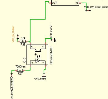
Schaltplan eines Optokopplers
OE/R VS VCC_24V_Outputsicher 10 GND_OUPUT 3 E 10k R38 2 1 4 C PC357N1TJ00F IC10 A K 1 2 7000Ohm R37 2 1 ON_ENABLE_INVERT GND_Board
in „Peaks bei powerup mit UDN2987“ · Mikrocontroller und Digitale Elektronik · · Schaltpläne
-
Datei
twi_test.c
///////////////////////////////////////////////////// // der bus sendet die addresse kriegt in ack udn // //sendet dan das register udn kriegt ein ack // // // // // //kriegt in ack udn sendet dan das register udn kriegt // //ein ack und kriegt ein ack // // // // // /////////////////////////////////
in „TWI/I2c Master läst Slave keine Datan senden“ · Mikrocontroller und Digitale Elektronik ·
-
PDF
VFD_Treiber_ic_6116.pdf
those used for handling MOS devices should be employed. Always order by complete part number, e.g., UDN6118A . 6118 VACUUM FLUORESCENT DISPLAY DRIVER UDN6118A PARTIAL SCHEMATIC ONE DRIVER (ALL TYPES) 1 18 VBB 30K 17 2 3 16 27K 4 15 RIN 14 INPUT 15K 5 OUTPUT R 6 13 B 125K 7 12 GND 8 11 Dwg. No. A-10,592C
in „Böse Vakuum-Fluoreszenz Anzeige“ · Analoge Elektronik und Schaltungstechnik ·
-
PDF
Wordclock-schmal.pdf
OUTPUT OUT0 C6 C3 100NF 100NF 100NF OUTR 100NF +12V VS GND GND KL2 47µF 100NF 47µF VCC RES\ SEROUT UDN2981A T1 OUTR 100NF R5 74HCT595N PWMR IRLU2905 GND GND GND GND GND GND GND GND GND GND GND GND IC5 82 OUTG IC9 R8 SERIN Q0 BQ0 BQ7 INPUT OUTPUT OUT15 SCK CLK Q1 BQ1 BQ6 INPUT OUTPUT OUT14 OUTB 10K SS
in „Wordclock V1.1 läuft nicht“ · Mikrocontroller und Digitale Elektronik ·
-
PDF
Blockschaltbild_der_RGB_Matrix_1.pdf
Verteilung der Portpins sowie die Struktur der Hardware Panel Drive ULN2804 8WIDARR 8WIDARR 8WIDARR CD4051 UDN2981 UDN2981 UDN2981 Control +B + PortA (0…7) PortC (0…7) PortD (0…7) +G PortB (0)1,2) ATmega162 +R @16Mhz +5V PRG GND Hardware Panel Drive Control Testaufbau mit 3 Stromquellen: Folgende Daten haben
in „RGB 8x8 LED Matrix 100HZ 8Bit PWM“ · Mikrocontroller und Digitale Elektronik ·
-
 Bild
Schaltplan mit ADuM1402ARW und PC357N1TJ00F
GND 10000 VCC_5V R22 700Ohm IC3 A C K E PC357N1TJ00F R21 10k SPIADUMENABLE_5V GND ADuM1402ARW GND1 VOD VOD2 VOD3 VOD4 GND1 VDD1 VDD2 GND2 VIB1 VIB2 SPI1_MISC SPI2_MISC SPI1_READY_5V SPI2_READY_5V SPI1_READY_5V SPI2_READY_5V SPI1_MISC SPI2_MISC SPI1_READY_5V SPI2_READY_5V C31 100nF VCC_3.3 C30 100nF GND VCC_5V
in „Peaks bei powerup mit UDN2987“ · Mikrocontroller und Digitale Elektronik · · Schaltpläne
-
PDF
tanke2.pdf
O5 I5 O5 6 I6 O6 11 6 I6 O6 13 7 I7 O7 10 7 I7 O7 12 8 GND CD+ 9 8 I8 O8 11 9 VS GND 10 ULN2003AN UDN2981A GND IC10 IC12 7 D0 Q 9 6 D1 Q0 3 5 D2 Q1 2 4 D3 Q2 4 3 D4 Q3 7 2 D5 Q4 10 1 14 1 15 D6 CLK Q5 5 14 D7 Q6 6 13 D8 Q7 9 re 12 D9 13 Q8 11 pS 11 D10 ENA Q9 re GND D11 1S0 15 RES CO 12 D - 10 O/E 3
in „Daten zu Ferranti-Display/Tanksäulenanzeige gesucht“ · Mikrocontroller und Digitale Elektronik ·
-
 Bild
Schaltplan mit 74HC595 und UDN2981
100n SRCLK SRCLR DE QA QB QC QD QE QG QH VCC GND IN1 IN2 IN3 IN4 IN5 IN6 IN7 IN8 OUT1 bis OUT7 GND U2 UDN2981 J3 VS_24V GND J4 SEG_A bis SEG_G
in „Schieberegister mit UDN2981A an Raspberry PI“ · Mikrocontroller und Digitale Elektronik · · Schaltpläne

-
PDF
tanke_bus_5.pdf
E 6 I6 O6 11 C 6 I6 O6 13 C 7 I7 O7 10 D 7 I7 O7 12 D 8 GND CD+ 9 8 I8 O8 11 9 VS GND 10 ULN2003AN UDN2981A GND IC10 7 D0 Q 9 IC12 6 3 5 D1 Q0 2 4 D2 Q1 4 3 D3 Q2 7 2 D4 Q3 10 D5 Q4 1 D6 14 CLK Q5 1 15 D7 Q6 5 14 D8 Q7 6 13 D9 Q8 9 cd 12 D10 13 ENA Q9 11 S 11 Oe GND D11 15 12 1S 0 10 RES CO D 5 O/E +
in „Daten zu Ferranti-Display/Tanksäulenanzeige gesucht“ · Mikrocontroller und Digitale Elektronik ·
-
PDF
tanke_bus_6.pdf
E 6 I6 O6 11 C 6 I6 O6 13 C 7 10 D 7 12 D 8 I7 O7 9 8 I7 O7 11 GND CD+ 9 I8 O8 10 VS GND ULN2003AN UDN2981A GND IC10 7 9 IC12 D0 Q 6 D1 Q0 3 5 D2 Q1 2 4 D3 Q2 4 3 D4 Q3 7 2 10 1 D5 14 Q4 1 15 D6 CLK Q5 5 14 D7 Q6 6 13 D8 Q7 9 e D9 Q8 Si 12 D10 13 ENA Q9 11 re GND 11 D11 p 15 RES CO 12 D 1 10 O/E 5 4017N
in „Daten zu Ferranti-Display/Tanksäulenanzeige gesucht“ · Mikrocontroller und Digitale Elektronik ·
-
PDF
tanke_bus_7.pdf
E 6 I6 O6 11 C 6 I6 O6 13 C 7 10 D 7 12 D 8 I7 O7 9 8 I7 O7 11 GND CD+ 9 I8 O8 10 VS GND ULN2003AN UDN2981A GND IC10 7 9 IC12 D0 Q 6 D1 Q0 3 5 D2 Q1 2 4 D3 Q2 4 3 D4 Q3 7 2 10 1 D5 14 Q4 1 15 D6 CLK Q5 5 14 D7 Q6 6 13 D8 Q7 9 e D9 Q8 Si 12 D10 13 ENA Q9 11 re GND 11 D11 p 15 RES CO 12 D 1 10 O/E 5 4017N
in „Daten zu Ferranti-Display/Tanksäulenanzeige gesucht“ · Mikrocontroller und Digitale Elektronik ·
-
PDF
tanke_bus_9.pdf
6 I5 O5 13 7 I6 O6 10 C 7 I6 O6 12 C I7 O7 D I7 O7 D 8 GND CD+ 9 8 I8 O8 11 9 VS GND 10 ULN2003AN UDN2981A 5 + 0 8 0 R 2 ICA3 ICB3 7 D0 Q 9 5 6 D1 Q0 3 GND 5 D2 Q1 2 5 4 D3 Q2 4 + 3 D4 Q3 7 2 D5 Q4 10 9 1 1 D6 14 CLK Q5 1 6 G 15 5 4 6 I 14 D7 Q6 6 13 D8 Q7 9 12 D9 13 Q8 11 11 D10 ENA Q9 D11 15 12 RES
in „Daten zu Ferranti-Display/Tanksäulenanzeige gesucht“ · Mikrocontroller und Digitale Elektronik ·
-
PDF
tanke_bus_10.pdf
6 I5 O5 13 7 I6 O6 10 C 7 I6 O6 12 C I7 O7 D I7 O7 D 8 GND CD+ 9 8 I8 O8 11 9 VS GND 10 ULN2003AN UDN2981A 5 + 0 8 0 R 2 ICA3 ICB3 7 D0 Q 9 5 6 D1 Q0 3 GND 5 D2 Q1 2 5 4 D3 Q2 4 + 3 D4 Q3 7 2 D5 Q4 10 9 1 1 D6 14 CLK Q5 1 6 G 15 5 4 6 I 14 D7 Q6 6 13 D8 Q7 9 12 D9 13 Q8 11 11 D10 ENA Q9 D11 15 12 RES
in „Daten zu Ferranti-Display/Tanksäulenanzeige gesucht“ · Mikrocontroller und Digitale Elektronik ·
-
PDF
V01.pdf
7 R5 QG 7 R6 R R6 8 I7 O7 11 11 O7 I7 8 R6 QH I 9 I8 O8 10 10 O8 I8 9 13 G QH* 9 VS GND CD+ GND Q8 UDN2981A ULN2803A IRLZ35N 10K B 74HC595N K 3 GND B GND 1 R GND R2 High-Side-Treiber Low-Side-Treiber +UB GND B IC7 IC8 A 1 18 18 1 14 15 C0 2 I1 O1 17 17 O1 I1 2 C0 SER QA 1 C0 C1 3 I2 O2 16 16 O2 I2 3
in „Ansteuerung einer Flip-Dot Matrix“ · Mikrocontroller und Digitale Elektronik ·
-
PDF
irlz24n.pdf
e 3Sw nC 1 DSFDFLL1 "gd rate-to-VdainF) qiGGed MFCyad±e PS° 1 GSFDF°S51 FkeeFli±SF2FanfF83F d(on) =udn-+nFVeGaOF=ibe wS8 1 DDFDFIP1 r RiseF=ibe wL ns @DFDF88m d(off) =udn-+00FVeGaOF=ibe I5 R GDF8IΩ, 1 FDF°S51 GS f laGGF=ibe IQ R DDFISLΩ, keeFli±SF85F µetpeenFGeaf D gD @ntednaGFVdainF@nfuctance LS° 2bbF
in „IR2127 Beschaltung als Low Side Schalter + Mosfet“ · Mikrocontroller und Digitale Elektronik ·
-
PDF
UDK2559B.pdf
2559 . Sh 4 e A t PROTECTED QUAD POWER DRIVER Providing improved output current limiting, the UDK, UDN, and UDx2559LB UDQ2559B, EB, and LB quad power drivers combine AND logic gates and high-current bipolar outputs with complete output protection. 1 16 Each of the four outputs will sink 700 mA in the
in „Suche UDK2559B Ersatz oder ähnliche Treiber ICs“ · Mikrocontroller und Digitale Elektronik ·
-
PDF
8x8_cubo.pdf
GND1 4 GND2 5 SV26 VIN 10 9 8 7 0 6 1 GND 5 4 2 3 3 1 2 4 2 JP3 1 5 3 1 6 7 1 DIGITAL_0_7 SV24 ULN-UDN_UD 2 9 3 1 2 8 VS GND I8 O8 4 3 4 7 I7 O7 5 8 5 6 6 I6 O6 6 9 7 8 5 I5 O5 7 10 9 10 4 I4 O4 8 11 11 12 3 I3 O3 9 12 13 14 2 I2 O2 10 13 15 16 1 I1 O1 GND 17 18 SV25 AREF IC1 SV23 DIGITAL_8_13 1 2 3
in „Led Cube 8x8x8 inventieren“ · Mikrocontroller und Digitale Elektronik ·
-
PDF
_Dokumentation_V1.0_Stand_22.03.2012.pdf
Säulen verbinden und alle Kathoden (- der LED) zu den Ebenen verbinden, entschied ich mich für den UDN2981A der den Latches nachgeschaltet wird. Danach noch die Vorwiderstände der LED’s…und fertig wäre der Säulen-Teil. Als Ebenentreiber wollte ich eigentlich einen (also 10, für jede Ebene einen) Transistor
in „Tutorial 10x10x10 LED-Cube“ · Mikrocontroller und Digitale Elektronik ·
-
PDF
eine-ebene.pdf
GND GND GND GND GND 13 9 + VS GND GREEN P$2 GREEN P$2 GREEN P$2 GREEN P$2 GREEN P$2 G QH* 4 9 1 1 2 UDN2983A L BLUE P$1 L BLUE P$1 L BLUE P$1 L BLUE P$1 L BLUE P$1 74HC595N IC7 14 15 1 18 GREEN_E4 P$4 P$4 P$4 P$4 P$4 SER QA 1 2 I1 O1 17 GREEN_E5 RED RED RED RED RED 11 QB 2 3 I2 O2 16 GND P$3 GND P$3 GND
in „Cube Schaltung verifizieren“ · Mikrocontroller und Digitale Elektronik ·
-
PDF
_Dokumentation_V1.2_Stand_29.03.2012.pdf
Säulen verbinden und alle Kathoden (- der LED) zu den Ebenen verbinden, entschied ich mich für den UDN2981A der den Latches nachgeschaltet wird. Danach nochdie Vorwiderständeder LED’s…undfertig wäre der Säulen-Teil. Als Ebenentreiber wollte ich eigentlich einen (also 10, für jede Ebene einen) Transistor
in „Tutorial 10x10x10 LED-Cube“ · Mikrocontroller und Digitale Elektronik ·
-
PDF
_Dokumentation_V1.6_Stand_04.08.2012.pdf
€ eBay hatte ich µC (ATMega) 1 Quarz 16MHz 1 hatte ich Latch (SN74HC573) 13 hatte ich LED-Treiber (UDN2981A) 13x á 1,50 € 15,00 € Reichelt Mosfets (IRLU024N) 10x á 0,42€ 4,20 € Reichelt IC-Sockel 43 hatte ich Verzinnter Kupferdraht 0,91mm², 86m 2 Rollen á 23,56 € 47,12 € Mercateo Artikelnummer: 139A-
in „Tutorial 10x10x10 LED-Cube“ · Mikrocontroller und Digitale Elektronik ·
-
PDF
MIC2981_82_8fach_Highside_Treiber.pdf
or PMOS logic outputs. Micrel’s • Relay and solenoid switching dual-marked device replaces either UDN2981 or UDN2982 • Stepping motor devices. • LED and incandescent displays The MIC2981/82 is available in the 18-pin plastic DIP and 18-lead wide SOP package. Both devices operate in the industrial temperature
in „Treiber Pendant zu ULN2803“ · Mikrocontroller und Digitale Elektronik ·
-
PDF
_Dokumentation_V1.7_Stand_27.02.2013.pdf
⃝ Quarz 16Mhz 1 „Reichelt Elektronik“ ⃝ „Reichelt Elektronik“ Latch (SN74HC573) 13 ⃝ LED Treiber (UDN2981A) 13 „Reichelt Elektronik“ ⃝ Mosfets (IRLU024N) 10 „Reichelt Elektronik“ ⃝ „Reichelt Elektronik“ 3 zu 8 Decoder (74HC238) 4 ⃝ IC Sockel 20-polig 13 „Reichelt Elektronik“ ⃝ IC Sockel 18-polig 13
in „Tutorial 10x10x10 LED-Cube“ · Mikrocontroller und Digitale Elektronik ·
-
PDF
_Dokumentation_V1.8_Stand_27.03.2013.pdf
⃝ Quarz 16Mhz 1 „Reichelt Elektronik“ ⃝ „Reichelt Elektronik“ Latch (SN74HC573) 13 ⃝ LED Treiber (UDN2981A) 13 „Reichelt Elektronik“ ⃝ Mosfets (IRLU024N) 10 „Reichelt Elektronik“ ⃝ „Reichelt Elektronik“ 3 zu 8 Decoder (74HC238) 4 ⃝ IC Sockel 20-polig 13 „Reichelt Elektronik“ ⃝ IC Sockel 18-polig 13
in „Tutorial 10x10x10 LED-Cube“ · Mikrocontroller und Digitale Elektronik ·
-
PDF
_Dokumentation_V1.9_Stand_23.09.2013.pdf
⃝ Quarz 16Mhz 1 „Reichelt Elektronik“ ⃝ „Reichelt Elektronik“ Latch (SN74HC573) 13 ⃝ LED Treiber (UDN2981A) 13 „Reichelt Elektronik“ ⃝ Mosfets (IRLU024N) 10 „Reichelt Elektronik“ ⃝ „Reichelt Elektronik“ 3 zu 8 Decoder (74HC238) 4 ⃝ IC Sockel 20-polig 13 „Reichelt Elektronik“ ⃝ IC Sockel 18-polig 13
in „Tutorial 10x10x10 LED-Cube“ · Mikrocontroller und Digitale Elektronik ·
-
 Bild
Schaltplan mit ICs, Dioden und Relais
IC3, IC2, UDN2981A, D1, D4, D10, D11, D12, RE1, RE2, RE3, RE4, RE5, RE6, RE7, RE8, RE9, RE10, RE11, RE12, 100NF, 1N4007
in „MCP23017 und UDN2981A“ · Mikrocontroller und Digitale Elektronik · · Schaltpläne

-
 Bild
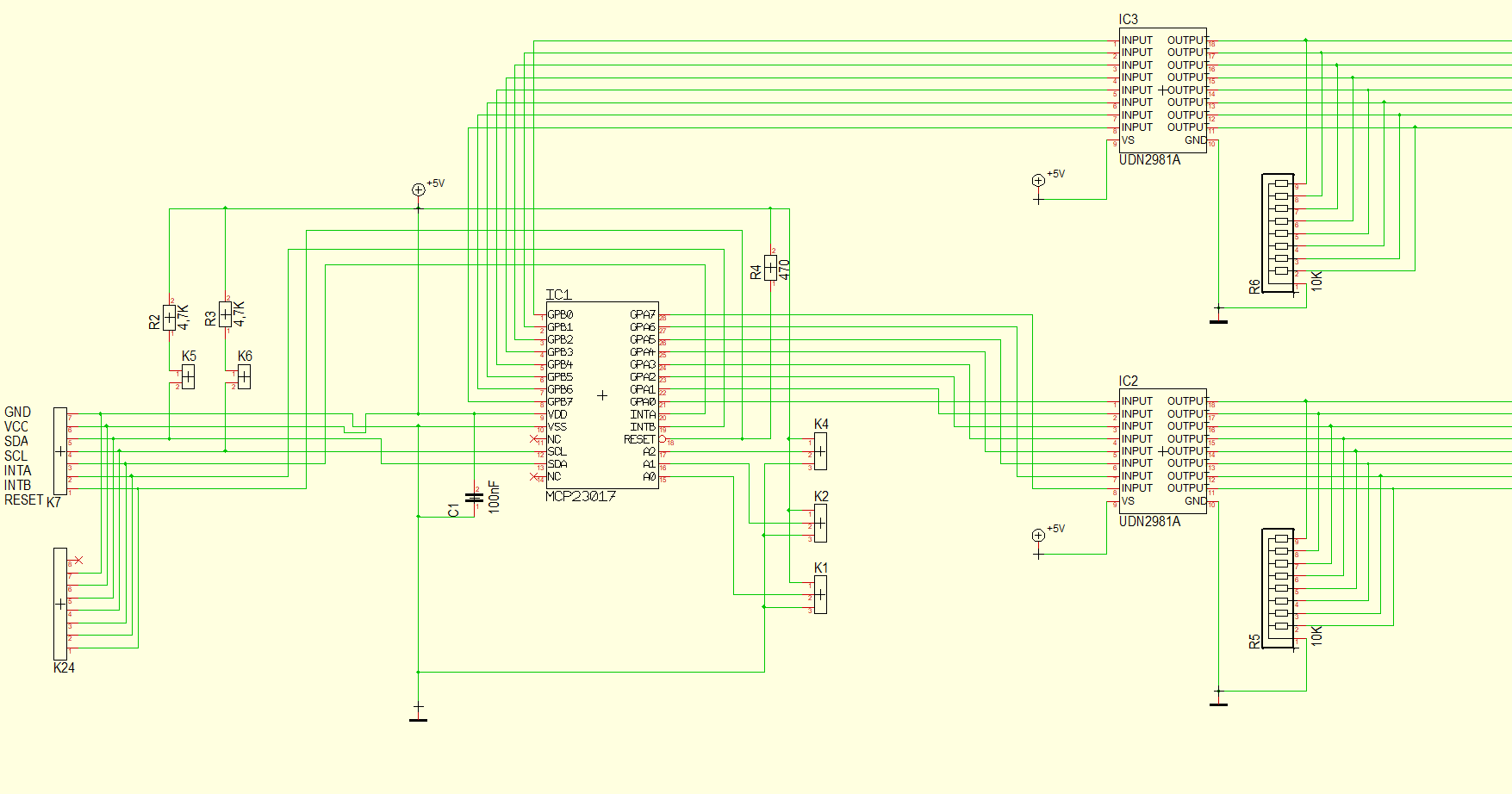
Schaltplan mit Mikrocontroller und Treiberchips
GPB0 bis GPB7 GPA0 bis GPA7 VDD VSS INTB RESET SCL SDA A0 A1 A2 F8 K1 K2 K4 R4 470 C1 100nF +5V IC2 UDN281A INPUT OUTPUT V5 GND R6 10K R5 10K
in „MCP23017 und UDN2981A“ · Mikrocontroller und Digitale Elektronik · · Schaltpläne
-
PDF
Elkoturm.pdf
Taltll'bat"/ocU Ge4"noh / wu/- r ,6 Gnun/ fla"u *'l A,o/ro/,soQ. 4i* LoT 6rQ'ts f" ka"d *uacta/ b udn r' /8"'' UoaL* "f g;aan'/'V qril 2h090' tL4''.1uün ä 0t Dnb w,e/ /'- Etko Tut'n /;'ttu ztgn> /19"' t^'/- onr,/f h*0 ,^ / r )/r,-r
in „Umrechnung MWh in F“ · Offtopic ·
-
PDF
LED_Anzeige_4x7_v03.pdf
c d e f g P 1 2 3 4 4 4 4 4 4 4 4 4 18 17 16 15 14 13 12 11 10 18 17 16 15 14 13 12 11 GND ULN2803 UDN2981A 1 2 3 4 5 6 7 8 GND 1 2 3 4 5 6 7 8 VCC 10 k RESET VCC 5V PD0 PB7 0V PD1 PB6 9V PA1 PB5 3 PA0 1 PB4 2 Ein/ y i Aus PD2 t PB3 A PD3 PB2 PD4 PB1 PD5 PB0 OUT 0V 5V GND PD6 9V Reset 0V
in „4x7 LED-Anzeige mit ULN2803 und UDN2981A - Berechnung Widerstände“ · Mikrocontroller und Digitale Elektronik ·
-
PDF
LED_Anzeige_4x7_v02.pdf
1 b 2 2 2 2 R R R R R R R R R R R R 18 17 16 15 14 13 12 11 10 18 17 16 15 14 13 12 11 GND ULN2803 UDN2981A 1 2 3 4 5 6 7 8 VSS 1 2 3 4 5 6 7 8 GND b R R R R R R R 3 R R R R R 10 k RESET VCC PD0 PB7 PD1 PB6 PA1 PB5 3 PA0 3 PB4 2 y i PD2 T PB3 A PD3 PB2 PD4 PB1 PD5 PB0 GND PD6 Reset 9V 0V 5V Ein/Aus +
in „4x7 LED-Anzeige mit ULN2803 und UDN2981A - Berechnung Widerstände“ · Mikrocontroller und Digitale Elektronik ·
-
PDF
Bauteile.pdf
RS232 Treiber max471CPA 1 DIP 5,00 € 74HCT138N 5 DIP 0,50 € AD8402 1 DIP 5,00 € ULN2803A 6 DIP 0,50 € UDN2981A 2 DIP 0,50 € LM358N 1 DIP 0,20 € CD74HC158 9 DIP MAX038CPP 2 DIP 5,00 € MM74HC595M 10 SO‐16 0,20 € A2982SLW‐T 19 SOIC‐20 1,50 € TLC5951DAP 5 HTSOP 2,50 € TLC59401PWP 10 HTSOP 2,50 € TBA2800 10
in „[V] diverse ICs“ · Markt ·
-
PDF
Bauteile.pdf
RS232 Treiber max471CPA 1 DIP 5,00 € 74HCT138N 5 DIP 0,50 € AD8402 1 DIP 5,00 € ULN2803A 6 DIP 0,50 € UDN2981A 2 DIP 0,50 € LM358N 1 DIP 0,20 € CD74HC158 9 DIP MAX038CPP 2 DIP 5,00 € MM74HC595M 10 SO‐16 0,20 € A2982SLW‐T 19 SOIC‐20 1,50 € TLC5951DAP 5 HTSOP 2,50 € TLC59401PWP 10 HTSOP 2,50 € TBA2800 10
in „[V] diverse ICs“ · Markt ·
-
PDF
IO-Schnittstellen.pdf
MC1)4049 150K R5 17 2A0 2Y0 3 2K2 15 2A1 2Y1 5 24 Ausgänge über TDE1798 13 7 2A2 2Y2 8 Ausgänge per UDN2982 11 2A3 2Y3 9 GND GND 1 1OE D 19 2OE G 0 1 B B J2 Ausgang 24V 1 +24V D1 D2 1N4007 1N4007 D3 1N5350 (13V) TDE1798 GND C 2 5 6 9 1 1 1 1 C 0 1 2 3 4 5 6 7 Q Q Q Q Q Q Q Q 20 10 U3 VCC GND 74LS273 0
in „Beispiele robuster Ein-/Ausgabe aus der Industrie“ · Mikrocontroller und Digitale Elektronik ·
-
PDF
pm55l048.pdf
Drive Voltage 24[V] 24[V] Current/Phase 800[mA] Coil Resistance/Phase 30[Ω] 5.5[Ω] Drive IC 2SC3346 UDN2916B-V PM Motor Magnet Material Ferrite plastic magnet (MSPL) Polar anisotropy ferrite sintered magnet (MS50) PM Type Nd-Fe-B bonded magnet (MS70) Insulation Resistance 100M[Ω] MIN Applications Dielectric
in „Frage zu Schrittmotor“ · Mikrocontroller und Digitale Elektronik ·
-
PDF
pm55l-048.pdf
Drive Voltage 24[V] 24[V] Current/Phase 800[mA] Coil Resistance/Phase 30[ ♣] 5.5[♣] Drive IC 2SC3346 UDN2916B-V Magnet Material Ferrite plastic magnet (MSPL) PM Motor Polar anisotropy ferrite sintered magnet (MS50) Nd-Fe-Bbonded magnet (MS70) PM Type Insulation Resistance 100M[♣] MIN Applications Dielectric
in „5-Pin Schrittmotor“ · Mikrocontroller und Digitale Elektronik ·
-
PDF
PM55L-048-E.pdf
Voltage 24[V] 24[V] Current / Phase 600[mA] Coil Resistance / Phase 30[ ] 6[ ] Drive I C SMDT-002 UDN2916B-V Magnet Material Ferrite plastic magnet Polar anisotropy ferrite sintered magnet Nd-Fe-B bonded magnet Insulation Resistance 100M[ ] MIN Dielectric Strength AC 500[V] 1[min] Class of Insulation
in „Welcher Schrittmotor für Drehpodest?“ · Mikrocontroller und Digitale Elektronik ·
-
Datei
efr.py
byte = 0 parity = 0 else: if t >= sample_time: # auf Abtastzeitpunkt warten if bitno < 9: # Daten udn Paritätsbit behandeln if bitno < 8: # Datenbit behandeln if b == 1: byte += 2**bitno parity ^= 1 else: # Paritätsbit behandeln parity ^= b sample_time += bit_time bitno += 1 else: # Stopbit behandeln
in „IQ demodulieren, was ist mit der Phase“ · Digitale Signalverarbeitung / DSP / Machine Learning ·
-
PDF
01.pdf
P$14 15 6 I5 O5 13 8 P$7 P$15 16 2 15 7 I6 O6 12 P$8 P$16 I7 O7 8 I8 O8 11 PC847 9 VS GND 10 3 14 UDN2981A IC4 4 13 IO+ 9 21 VDD GPA0 22 OK2C GPA1 PC847 18 RESET GPA2 23 5 12 OUT IN GPA3 24 20 INTA GPA4 25 6 11 GND 19 26 IC2 INTB GPA5 27 PC847 3,3V IO_GND 11 GPA6 28 7 10 12 CS GPA7 SCK 13 SI GPB0 1
in „IOs von externer Steuerung (SPS, Raspberry) zu µC“ · Mikrocontroller und Digitale Elektronik ·
-
PDF
tanke.pdf
I5 O5 14 6 I6 O6 11 6 I6 O6 13 7 I7 O7 10 7 I7 O7 12 8 GND CD+ 9 8 I8 O8 11 9 VS GND 10 ULN2003AN UDN2981A 06.07.2014 17:06:11 f=0.90 C:\Users\holger\Documents\eagle\Neues_Projekt\tanke.sch (Sheet: 1/1)
in „Daten zu Ferranti-Display/Tanksäulenanzeige gesucht“ · Mikrocontroller und Digitale Elektronik ·
-
Datei
ports.h
Funktionsbekanntgabe + Taster ///////// ///////////////////////////////////////////////////// //LED udn AUSGANG #define LEDDDR DDRB #define LEDPORT PORTB #define LED1 PB1 //Relais #define RELAISDDR DDRB #define RELAISPORT PORTB #define RELAISPIN PINB #define RELAIS PB7 //Taster #define TASTERDDR DDRD
in „Atmega8 PB7 als Ausgang für Relais“ · Mikrocontroller und Digitale Elektronik ·