OK I has been done with UNO based on code from Tadej, I think it's same
with NANO setup.
I only change in serial setup from serial2 to serial0.
I has been followed this topic since November 2013 and beginning to try
again a few month ago.

Thank you for everything.
I'm sorry for the late reply. Did you manage to make it work? If not I
can also post code for the UNO/Nano version.
I made it work with a Nano (MEGA328) and 5 i2c PWM output expanders. I
have been testing this slave for 3 months now with no profibus errors.
It works great but only goes up to 45.45k speed
Anyway those 5 PWM expander provide 48 PWM outputs!
Hallo,
It is great. I also test with DS18B20 temperature sensor.
Now I still test to ATMega32 based arduino MIGHTYCORE but not success
yet.
@Tadej if you have code is wellcome.

Regards
Michael schrieb:> Dear mr. Jörg S!> Many thanks for such an excellent implementation of the Profibus DP> software slave. With minor changes, on the Cortex-M0 I achieved a stable> exchange rate of 3Mb / sec. Thanks again for such a wonderful job!> Best Regards, Michael.
Michael, can you share the code?
Tadej S. schrieb:> Hello!>> I would like to share my adaption of your software to Arduino MEGA2560> Hope it helps someone!
Hello TadyTheFish,
I use a Controllino Mega and would like to use your implementation.
https://www.controllino.biz/wp-content/uploads/2018/10/CONTROLLINO-MEGA-Pinout.pdf
In the Controllino is an SN65HVD08, which should actually work the same
way.
Your code contains a lot of assembler, which I cannot.
Can you rewrite me your code that I can work with RX3-TX3 instead of
RX2-TX2.
Thanks.
Ridchi
If still use the same controller with Arduino mega maybe you just change
the register related serial3 and also consider the working clock for the
CPU. In uno / nano I just change the register serial2 to serial0 from
Tadej's code. You can read the Atmega2560 datasheet to find the
register.
Hello

Sorry for the late reply. I have editedd the programs and made 3
versions.

Mega2560 UART2
Mega2560 UART3
Mega328

I have not tested the UART3 version so please if it works leave reply or
if it dos not :)

EDIT: Whoops.. both attachements are the same :D
Sorry I don't. I work with arduino IDE and those chips are not included
by default and I never had a need for them. You could addopt the code to
work with those chips but you need to find the registers for UART and
Timer and change them to suite those chips
Tadej S. schrieb:> Hello>> Sorry for the late reply. I have editedd the programs and made 3> versions.>> Mega2560 UART2> Mega2560 UART3> Mega328>> I have not tested the UART3 version so please if it works leave reply or> if it dos not :)>> EDIT: Whoops.. both attachements are the same :D
Hello Tadej,
i have test the Mega2560 UART3.
You have forgotten to change in row 853:
1
UCSR2B|=_BV(UDRIE2);// <<< AVR Version
into
1
UCSR3B|=_BV(UDRIE3);// <<< AVR Version
then it works.


But I get a lot of warnings when compiling.
The Problem is the conversion from unsigned char* into char*

for example:
Hmm thank you for your input.. Maybe you could upload the corrected
version?
I'm sorry so much things to do and so little time. I remember this
problem the IDE was failing to compile the original version when I was
"porting" the code.
Anyway the mega328 version is running on my friends test bench for 3
months and 2 day till today...
Maybe I forgot to change this in the mega2560 code I don't know I didn't
really gave much attention since it works for my friend
But it works with 45.45k. I can't remember seeing the baudrate you have
specified in WinCC or TIA portal.. But I am not really the PLC
programming guy. I just helped my friend that is a Simatic guru ?
I just found out that why the code compiled properly on my IDE..
Compiler warnings were turned off :) thabk you so much.

I have corrected the registers that you have pointed out. Yes I have
changed on the bottom and I missed the TX routine that needed changing ?

As I said its been 3 month since I last saw the code ?

The +5 is not an offset i expanded the buffer because I had problems and
I couldn't find what was wrong. The program was crashin so I tought that
maybe the program goes out of bounds somwhere but in the end there was a
problem with a poor profibus connection.. You can remove the +5 it
should work the same.. Or you can leave it there is more than enough
space
Tadej S. schrieb:> Sorry I don't. I work with arduino IDE and those chips are not included> by default and I never had a need for them. You could addopt the code to> work with those chips but you need to find the registers for UART and> Timer and change them to suite those chips
Maybe you can try to add the hardware ATmega16 or 32 from mightycore
https://github.com/MCUdude/MightyCore
I just have problem in how to compile from your code (Arduino mega) to
mega32 controller. It's many error that I do not understand. If you can
compile without error I can try to the my hardware hardware.
M@tti@ schrieb:> Hi at all, anybody have an example to read an digital input on the> Arduino and write in the PLC and viceversa?>> Many thanks at all>> M@tti@
Tadej's code have io access.
you must write for correctly syntax

if (checksum((char*)&uart_buffer[1], 3) != FCS_data) break;

!!!!!!!!

The same with the other line with Checksum ()

Ridchi
The errors you posted should actually be warnings.
The problem is with registers. Mega32 uses completely different
registers then a meva328 or 2560 uses. The code needs alot of adapting
to run on an mega32.

Why don't you upgrade to a different MCU?
Hi @Amigo I., and many thanks for the reply.
I tried the Tadej S. code, but without result, in the PC i don't see the
state of the digital input (for example Arduino pin 4) change.
How is mapped this digital input (pin 4) of Arduino in the PLC?
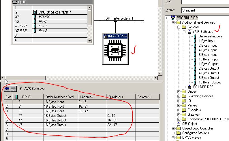
In the Hardware Configuration (Step7) i have make for first an Universal
Module, for second 1 byte Input and for third 1 byte Output. It's ok
this configuration?
Do you have an example or a screenshot of your project that works?
Thank you very much
M @ TTI @
You must Write the state of Pin4 as Bit0 in data_out_register[0] then
you can used this in PLC I1.0 ect... The input Adress is this who
configured it in Hardwareconfig.
Tadej S. schrieb:> The errors you posted should actually be warnings.> The problem is with registers. Mega32 uses completely different> registers then a meva328 or 2560 uses. The code needs alot of adapting> to run on an mega32.>
Hi Tadej,
I already change the Mega32 register, no error found related register.
Only the error: invalid conversion from 'unsigned char*'
to 'char*' [-fpermissive] too many appear. I thing it's not hardware
setting but about format to write. I not to much familiar with C.
> Why don't you upgrade to a different MCU?
Because I have few of Mega16 / Mega32 :)
thank
M@tti@ schrieb:> Hi @Amigo I., and many thanks for the reply.> I tried the Tadej S. code, but without result, in the PC i don't see the> state of the digital input (for example Arduino pin 4) change.> How is mapped this digital input (pin 4) of Arduino in the PLC?> In the Hardware Configuration (Step7) i have make for first an Universal> Module, for second 1 byte Input and for third 1 byte Output. It's ok> this configuration?> Do you have an example or a screenshot of your project that works?>> Thank you very much>> M @ TTI @
You can play the variable "data_in_register" and "data_out_register"
related the I/O in "doit" routine.
In Simatic you can see in variable table.
Michael schrieb:> Dear mr. Jörg S!> Many thanks for such an excellent implementation of the Profibus DP> software slave. With minor changes, on the Cortex-M0 I achieved a stable> exchange rate of 3Mb / sec. Thanks again for such a wonderful job!> Best Regards, Michael.
and what RS485-UART chip did you get in contact with at 1.5Mb/s?
Peter F. schrieb:> Hello,>> I changed code from project AVRSoftBus for atXmega32A4U. It's run on> 48Mhz. I tested both speed 187500 and 1M5, everything work. In> profibus.h need change UART_BAUD and DELAY_TBIT. I used USART D0. I> believe this code is usable for someone.
Hello, and what RS485-UART chip did you get in contact with at 1.5Mb /
s?
Yes and we have all of you to thank! I ported the code to arduino and
now i ported it to STM32F405. I got a stable connection at 6Mbits
Only now that i have worked with your code I understand the bus. So
thank you again
Hallo,
es ist zwar schon etwas älter hoffe aber trotzdem auf Hilfe.
Ich beschäftige mich gerade mit diesem Thema und habe da ein paar
„kleine“ Probleme bei diesem Programm.
Zum Einsatz kommt eine S7-315-2DP und einen Atmega16
Die Dateien in meinem Programm sind vom 28.4.2010 (hoffe das es die
aktuellste Version ist)

Die Funktion
1
slave_addr=get_Address();
Gibt es diese oder muss man die wenn nötig selbst erstellen?
Die Auskommentierten Zeilen sind nicht in der .c bzw .h Datei enthalten,
werden diese Benötigt?

Wie genau kann ich jetzt dann Daten Senden oder Empfangen… stehe
irgendwie gerade auf dem Schlauch.
Hallo,
die Funktion "get_Address()" muss man sich schon selber schreiben.
Es weiß ja sonst keiner wo und wie die Adresseingabe erfolgt.
Ich habe bei einem Prokekt über ein 74HC166 eingelesen, bei einem
anderen Projekt direkt über die GPIOs.
>Die Auskommentierten Zeilen sind nicht in der .c bzw .h Datei enthalten,>werden diese Benötigt?
Deine GPIOs, UARTs, Timer, etc musst du schon initialisieren.
Je nach MCU verschieden.
>Kann ich hiermit Daten schon senden wenn sie im uart_buffer stehen??
Ich würde sagen ja.
Tipp:
Bau dir einen RS485->RS232 Sniffer, dann kannst du mit hterm die Daten
in Hex ansehen. Hat mir öfters geholfen.
Hallo,

dank für die Antwort.
Dann habe ich das soweit verstanden und werde mal schauen das ich das
jetzt zum Laufen bekommen.

Das mit dem Sniffer ist kein schlechter Vorschlag, wird ich mich mal
einen Bauen.
Hello, nice job!
I'm using this code to play with industrial items,
everything works until i add "liquidcrystal" library,
it does the setup, but when in the "loop"
the LCD goes back to reset.
Does Timer or Uart affects its usage?
Thank you
Hallo,

ich beschäftig ich jetzt schon etwas länger mit dem Thema und bekomme
das nicht zum laufen... habe einen sehr einfachen Code genommen soll nur
etwas Senden.

Als Vorlage habe ich die Bibliothek verwende wo schon vorhanden ist
(9.2009 (Aktueller Stand)).
Als Übertragungsgeschwindigkeit habe ich auf dem Mikrocontroller sowie
im TIA Portal 45,45 kBit/s eingestllet (Im TIA Portal bringt er bei den
anderen Fehlermeldungen.
In der SPS Hardware Config zeigt er mir auch Teilnehmer nicht
erreichbar.

Habe ich hier in dem Programm noch etwas vergessen. In der Bibliothek
habe ich nichts verändert.
Du kannst nicht einfach was an einen Master senden.

Der Master macht eine zyklische Anfrage, dann muss eine definierte
Wartezeit eingehalten werden, erst dann erfolgt die Antwort.

Google mal nach "Profibus Felser" dort findest du eine gute Erklärung
mit allen Abläufen.

Wenn du einen Frame erhalten hast startest du einen Timer mit 33
Bitzeiten.
Wenn der Timer abgelaufen ist sendest du die Antwort.

.. und vergiss nicht die Richtung am RS485 Tranceiver umzuschalten.
Hallo,
ich weiß, dass der Thread schon fast zwei Jahre her ist.. Ist das
Projekt noch aktiv und wird noch daran gearbeitet?
Ich schätze diese Arbeit sehr und finde kaum andere Lösungen als diese
hier. Die, die ich finde, sind diesem Code sehr ähnlich.

Mit freundlichen Grüßen
Mathias Shabo
Mathias Shabo schrieb:> Ist das Projekt noch aktiv und wird noch daran gearbeitet?
Am Ursprungsprojekt wird nicht weiter gearbeitet. Updates wird es da
also nicht geben.