Hi Leute

Ich brauche einen gängigen Touchscreen Controller für einen 4-Wire
resistiven Touch auf einem 5,7" TFT Display.

Er sollte SPI Interface und IRQ Ausgang bieten.
Das Gehäuse am liebsten SO oder TSOP.
ADC Auflösung 12-Bit.

Kennt jemand ein gut erhältliches Teil?

Im Voraus besten Dank...
Perfekt, danke schön...

Der MXB7846 von Maxim ist evt. sogar kompatibel.
Ich habe bei meinem Touch übrigens unübliche Bezeichnungen.
Vielleicht kann mir da auch jemand Gewissheit geben...

YU = Y+
XL = X+
YD = Y-
XR = X-

stimmt das so?
Hallo,
Andreas Häusler schrieb:
> YU = Y+
> XL = X+
> YD = Y-
> XR = X-

Hab mir spontan folgendes gedacht:

YU = Y_up
YD = Y_down

XL = X_left
XR = X_right

mfg mf
Danke Jo...

Ja, hab ich mir auch gedacht, aber stimmt demzufolge meine Definition:

YU = Y+
XL = X+
YD = Y-
XR = X-
Andreas Häusler schrieb:
> Der MXB7846 von Maxim ist evt. sogar kompatibel.

Nicht nur eventuell, der TSC2046E ist sogar Pin kompatibel zu dem 7846.
Ich würde, um den X Wert zu messen, an XL niedriges und an XR hohes
Potential applizieren. Damit kommt man je weiter man Rechts ist, an
höhere Spannungswerte für X.

Mit Y ist es so, dass das Koordinatensystem umgedreht zum
Matheunterricht der 6. Klasse ist, weil Bildschirme traditionell wie ein
Blatt Papier händisch mit Stift beschrieben werden. An YD müsste also
hohes, an YU niedriges Potential, um nach unten hin höhere AD-Werte zu
lesen.

Wie das der Touchcontroller macht, weiß ich nicht. Ich würde das einen
kleinen Atmel machen lassen.

mfg Jo
Andreas Häusler schrieb:
> Ja, hab ich mir auch gedacht, aber stimmt demzufolge meine Definition:

Nein.
So:
YU = Y+
XL = X-
YD = Y-
XR = X+
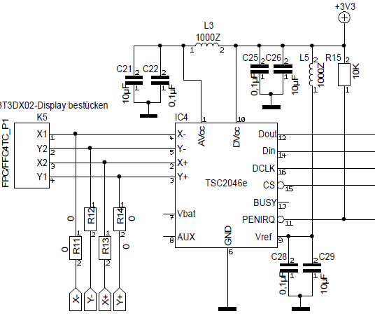
Danke für die Info!

Aber nach folgendem Auszug aus einer Freescale App, ergiebt sich:

YU = Y+
XL = X+
YD = Y-
XR = X-

-----------------------
1.1.1 Example of 4-Wire Touch Screen Measurement
Figure 1 shows an example of how measurements would be taken on a 4-wire
touch screen. The first step
is to get the x-axis coordinate. To do this X+/XL is biased to 3.3 V,
and X–/XR is biased to 0 V. At this
point there should be a consistent voltage ramp across the x-axis plane.
If the screen is touched in the
center, the mid-level voltage of 1.65 V is transferred to the y-axis
plane. The Y+/YU and Y–/YD points
are floating, so the entire plane should be at 1.65 V. This input
voltage is read from the Y+/YU connection
and used to determine that the x-axis coordinate of the touch point is
at 50% of the screen’s width.
The next step is to get the y-axis coordinate. This time Y+/YU is biased
to 3.3 V, and Y–/YD is biased to
0 V. This creates the consistent voltage ramp across the y-axis plane.
The pressure from the touch creates
a contact point between the two planes so that the x-axis plane goes to
1.65 V. The input voltage is read
from the X+/XL wire and used to determine that the y-axis coordinate of
the touch point is at 50% of the
screen’s height.
-----------------------

Verwende zur Zeit die Microchip Grafik Lib und steuere den Touch meines
Displays (Glyn:ET0350G0DH6) direkt über analoge- und digitale Ports an.
Hab jetzt das Problem, dass die Software nicht auf die Berührung des
Touches reagiert. Das original Truly- Display lief einwandfrei.
Hab gesehen, dass auf dem Original Display noch 2 Pullup Widerstände (je
100k) von X+ und Y+ auf 3,3V geschaltet sind.
Muss ich diese auch vorsehen?
Könnte es sein, dass trotzem jrgendwie X und Y vertauscht sind oder muss
ich den Treiber auf den neuen Touch anpassen?
Wieso nutzt du dann nicht auch den AR1020 oder AR1010?

Die linearisieren dir die Koordinaten wenigstens gleich :)
Bitte melde dich an um einen Beitrag zu schreiben. Anmeldung ist kostenlos und dauert nur eine Minute.
Bestehender Account
Schon ein Account bei Google/GoogleMail? Keine Anmeldung erforderlich!
Mit Google-Account einloggen
Mit Google-Account einloggen
Noch kein Account? Hier anmelden.