1 | The supply voltage limits the minimum value of resistor Rp due to the specified minimum sink current of 3 mA at VOLmax = 0.4 V for the output stages.
|
2 | VDD as a function of Rp min is shown in Fig.37.
|
3 | The required noise margin of 0.1VDD for the LOW level, limits the maximum value of Rs.
|
4 | Rs max as a function of Rp is shown in Fig.38.
|
5 | The bus capacitance is the total capacitance of wire, connections and pins. This capacitance limits the maximum value of Rp due to the specified rise
|
6 | time. Fig.39 shows Rp max as a function of bus capacitance.
|
7 |
|
8 | The maximum HIGH level input current of each input/output connection has a specified maximum value of 10 mA.
|
9 | Due to the required noise margin of 0.2 VDD for the HIGH level, this input current limits the maximum value of Rp.
|
10 | This limit depends on VDD. The total HIGH level input current is shown as a function of Rp max
|
Wenn ich das nun richtig verstanden habe:

Rp muss ausreichend klein sein dass die RiseTime eingehalten wird.

Daher das ich zwei Geräte am Bus habe und die maxRiseTime bei 300ns
liegt:

1/(2pi*3,33MHz*20pF) = ~2,5kOhm


Desweiteren dürfen bei einer Last von 10µA pro Gerät über Rp nicht mehr
als 0,2V abfallen:

0,2V/20µA = 10kOhm


Was die Serienwiderstände angeht verstehe ich die Bedingungen nicht
ganz.

Bei einem Mindeststrom von 3mA dürfen nicht mehr als 0,4V abfallen.
Der benötigte Rauschabstand für den Low Level beträgt 0,1V und begrenzt
die größe vom Serienwiderstand.

Heißt das:

Mindestens: 5V/3mA = 1,66kOhm
Maximal: So das Low min. 0,1V unter dem Höchsten als Low erkannten Pegel
liegt.


Habe ich da irgendwelche Fehler drinne oder habe ich das richtig
verstanden?

Quelle: Obriges .pdf Seite 39

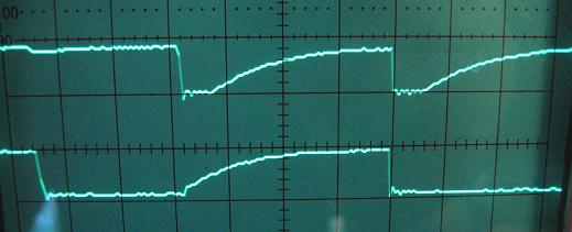
 I2C_006klein.JPG
(23 KB)
I2C_006klein.JPG
(23 KB)