1 | /**
|
2 | ******************************************************************************
|
3 | * @file DAC-ADC /main.c
|
4 | * @author Jan Heynen
|
5 | * @version V1
|
6 | * @date 1/1/2012
|
7 | * @brief Main program body.
|
8 | ******************************************************************************
|
9 | * @copy
|
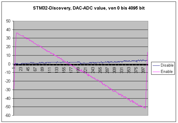
10 | * The DAC_Channel1 will send a Voltage to pin PA4, DAC channel2 to pin PA5. The ADC is measured on
|
11 | * pin PA4 and pin PA5. DAC PA4, the Buffer is diasable, DAC PA5, the Buffer is enabled.
|
12 | * The differens between DAC and ADC is printed via USART1 (38400 baud)
|
13 | */
|
14 |
|
15 | /* Includes ------------------------------------------------------------------*/
|
16 | #include "stm32f10x.h"
|
17 | #include <stdio.h>
|
18 | /* Private typedef -----------------------------------------------------------*/
|
19 | #define LEDC8_OFF GPIOC->BRR = 1<<8 ;
|
20 | #define LEDC9_OFF GPIOC->BRR = 1<<9 ;
|
21 | #define LEDC8_ON GPIOC->BSRR = 1<<8 ;
|
22 | #define LEDC9_ON GPIOC->BSRR = 1<<9 ;
|
23 | /* Private define ------------------------------------------------------------*/
|
24 | #define DAC_DHR12RD_Address 0x40007420
|
25 |
|
26 | /* Init Structure definition */
|
27 | DAC_InitTypeDef DAC_InitStructure;
|
28 | DMA_InitTypeDef DMA_InitStructure;
|
29 | TIM_TimeBaseInitTypeDef TIM_TimeBaseStructure;
|
30 | /* Private macro -------------------------------------------------------------*/
|
31 | /* Private variables ---------------------------------------------------------*/
|
32 | uint8_t Idx = 0;
|
33 | uint16_t adc0=0;
|
34 | uint16_t i=0;
|
35 | volatile uint16_t Delay;
|
36 | /* Private function prototypes -----------------------------------------------*/
|
37 | void RCC_Configuration(void);
|
38 | void GPIO_Configuration(void);
|
39 | void delay(uint16_t tijd);
|
40 | void USART_Config(void);
|
41 | #ifdef __GNUC__
|
42 | /* With GCC/RAISONANCE, small printf (option LD Linker->Libraries->Small printf
|
43 | set to 'Yes') calls __io_putchar() */
|
44 | #define PUTCHAR_PROTOTYPE int __io_putchar(int ch)
|
45 | #else
|
46 | //#define PUTCHAR_PROTOTYPE int __io_putchar(int ch)
|
47 | #define PUTCHAR_PROTOTYPE int fputc(int ch, FILE*f)
|
48 | #endif /* __GNUC__ */
|
49 | PUTCHAR_PROTOTYPE //in main achteraan
|
50 | {
|
51 | /* Place your implementation of fputc here */
|
52 | /* e.g. write a character to the USART */
|
53 | USART_SendData(USART1, (uint8_t) ch);
|
54 |
|
55 | /* Loop until the end of transmission */
|
56 | while (USART_GetFlagStatus(USART1, USART_FLAG_TC) == RESET)
|
57 | {}
|
58 |
|
59 | return ch;
|
60 | }
|
61 | /* Private functions ---------------------------------------------------------*/
|
62 | static __IO uint32_t TimingDelay;
|
63 | void TimingDelay_Decrement(void)
|
64 | {
|
65 | if (TimingDelay != 0x00)
|
66 | {
|
67 | TimingDelay--;
|
68 | }
|
69 | }
|
70 | void ADC_Configuration(void){
|
71 | ADC_InitTypeDef ADC_InitStructure; /* PCLK2 is the APB2 clock */ /* ADCCLK = PCLK2/6 = 72/6 = 12MHz*/
|
72 | RCC_ADCCLKConfig(RCC_PCLK2_Div6); /* Enable ADC1 clock so that we can talk to it */
|
73 | RCC_APB2PeriphClockCmd(RCC_APB2Periph_ADC1, ENABLE); /* Put everything back to power-on defaults */
|
74 | ADC_DeInit(ADC1); /* ADC1 Configuration -*/ /* ADC1 and ADC2 operate independantly */
|
75 | ADC_InitStructure.ADC_Mode = ADC_Mode_Independent; /* Disable the scan conversion so we do one at a time */
|
76 | ADC_InitStructure.ADC_ScanConvMode = DISABLE; /* Don't do contimuous conversions - do them on demand */
|
77 | ADC_InitStructure.ADC_ContinuousConvMode = DISABLE; /* Start conversin by software, not an external trigger */
|
78 | ADC_InitStructure.ADC_ExternalTrigConv = ADC_ExternalTrigConv_None; /* Conversions are 12 bit - put them in the lower 12 bits of the result */
|
79 | ADC_InitStructure.ADC_DataAlign = ADC_DataAlign_Right; /* Say how many channels would be used by the sequencer */
|
80 | ADC_InitStructure.ADC_NbrOfChannel = 1; /* Now do the setup */
|
81 | ADC_Init(ADC1,&ADC_InitStructure); /* Enable ADC1 */
|
82 | ADC_Cmd(ADC1, ENABLE); /* Enable ADC1 reset calibaration register */
|
83 |
|
84 | ADC_ResetCalibration(ADC1); /* Check the end of ADC1 reset calibration register */
|
85 | while(ADC_GetResetCalibrationStatus(ADC1)); /* Start ADC1 calibaration */
|
86 | ADC_StartCalibration(ADC1); /* Check the end of ADC1 calibration */
|
87 | while(ADC_GetCalibrationStatus(ADC1));
|
88 | }
|
89 |
|
90 | u16 readADC1(u8 channel){
|
91 | ADC_RegularChannelConfig(ADC1, channel, 1, ADC_SampleTime_41Cycles5); // Start the conversion
|
92 | ADC_SoftwareStartConvCmd(ADC1, ENABLE); // Wait until conversion completion
|
93 | while(ADC_GetFlagStatus(ADC1, ADC_FLAG_EOC) == RESET); // Get the conversion value return ADC_GetConversionValue(ADC1);}
|
94 | return ADC_GetConversionValue(ADC1);}
|
95 | /**
|
96 | * @brief Main program.
|
97 | * @param None
|
98 | * @retval None
|
99 | */
|
100 | int main(void)
|
101 | {
|
102 | /* System Clocks Configuration */
|
103 | RCC_Configuration();
|
104 | GPIO_Configuration();
|
105 | ADC_Configuration(); //configuratie ADC1
|
106 | /* Once the DAC channel is enabled, the corresponding GPIO pin is automatically
|
107 | connected to the DAC converter. In order to avoid parasitic consumption,
|
108 | the GPIO pin should be configured in analog */
|
109 | /* DAC channel1 Configuration */
|
110 | DAC_InitStructure.DAC_Trigger = DAC_Trigger_None ;
|
111 | DAC_InitStructure.DAC_WaveGeneration = DAC_WaveGeneration_None ;
|
112 | DAC_InitStructure.DAC_OutputBuffer = DAC_OutputBuffer_Disable;
|
113 | DAC_Init(DAC_Channel_1, &DAC_InitStructure);
|
114 | /* DAC channel2 Configuration */
|
115 | DAC_InitStructure.DAC_OutputBuffer = DAC_OutputBuffer_Enable;
|
116 | DAC_Init(DAC_Channel_2, &DAC_InitStructure);
|
117 | /* Enable DAC Channel1: Once the DAC channel1 is enabled, PA.04 is
|
118 | automatically connected to the DAC converter. */
|
119 | DAC_Cmd(DAC_Channel_1, ENABLE);
|
120 | /* Enable DAC Channel2: Once the DAC channel2 is enabled, PA.05 is
|
121 | automatically connected to the DAC converter. */
|
122 | DAC_Cmd(DAC_Channel_2, ENABLE);
|
123 | /* Set DAC dual channel DHR12RD register */
|
124 | DAC_SetDualChannelData(DAC_Align_12b_R, 0x100, 0x100);//was 0x100,0x100
|
125 |
|
126 | /* USARTx configured as follow:
|
127 | - BaudRate = 38400 baud
|
128 | - Word Length = 8 Bits
|
129 | - One Stop Bit
|
130 | - No parity
|
131 | - Hardware flow control disabled (RTS and CTS signals)
|
132 | - Receive and transmit enabled
|
133 | */
|
134 | USART_InitTypeDef USART_InitStructure;
|
135 | USART_InitStructure.USART_BaudRate = 38400;
|
136 | USART_InitStructure.USART_WordLength = USART_WordLength_8b;
|
137 | USART_InitStructure.USART_StopBits = USART_StopBits_1;
|
138 | USART_InitStructure.USART_Parity = USART_Parity_No;
|
139 | USART_InitStructure.USART_HardwareFlowControl = USART_HardwareFlowControl_None;
|
140 | USART_InitStructure.USART_Mode = USART_Mode_Tx;
|
141 |
|
142 |
|
143 | /* USART configuration */
|
144 | USART_Init(USART1, &USART_InitStructure);
|
145 |
|
146 | /* Enable USART */
|
147 | USART_Cmd(USART1, ENABLE);
|
148 | /* Systick timer----- ------------------------------------------------------*/
|
149 | /* Setup SysTick Timer for 1 msec interrupts */
|
150 | if (SysTick_Config(SystemFrequency / 1000))
|
151 | {
|
152 | while (1);/* Capture error */
|
153 | }
|
154 | /* Display Demo start */
|
155 | LEDC8_ON;
|
156 | delay(1000);
|
157 | printf("\n\r\n STMICROELECTRONICS\n\r");
|
158 | printf("\n\r ********** STM32 - DAC-ADC Demo **********\n\r");
|
159 | printf("\n\r Gebruik FULL voor de library configurator !!! \n\r");
|
160 | LEDC8_OFF;
|
161 | //Main Schleife
|
162 | while (1)
|
163 | {
|
164 | for (;i<4096;){
|
165 | DAC_SetDualChannelData(DAC_Align_12b_R, i,i);//Dacchannel 1 + 2 Ansteuern mit Werte i
|
166 | LEDC9_ON;
|
167 | delay(10); //Wartezeit 10 ms
|
168 | LEDC9_OFF;
|
169 | delay(10);
|
170 | adc0=readADC1(4); //ADC Einzelabtastung Channel 4 = pin A4
|
171 | printf("DAC: %d ",i); //Print Soll wert DAC
|
172 | printf(" ADC4: %d ",(i-adc0)); //Print differenz DAC - ADC Messwert channel 4
|
173 | adc0=readADC1(5);
|
174 | printf(" ADC5: %d\n ",(i-adc0));//Print differenz DAC - ADC Messwert channel 5
|
175 | i=i+10; //DAC Werte mit 10 erhohen
|
176 | }
|
177 | }
|
178 | }
|
179 |
|
180 | /* @brief Configures the different system clocks. */
|
181 | void RCC_Configuration(void)
|
182 | {
|
183 | /* Setup the microcontroller system. Initialize the Embedded Flash Interface,
|
184 | initialize the PLL and update the SystemFrequency variable. */
|
185 | SystemInit();
|
186 | /* Enable peripheral clocks --------------------------------------------------*/
|
187 | /* GPIOA and GPIOC Periph clock enable */
|
188 | RCC_APB2PeriphClockCmd(RCC_APB2Periph_GPIOA|RCC_APB2Periph_GPIOC, ENABLE);
|
189 | RCC_APB1PeriphClockCmd(RCC_APB1Periph_PWR, ENABLE);
|
190 | /* DAC Periph clock enable */
|
191 | RCC_APB1PeriphClockCmd(RCC_APB1Periph_DAC, ENABLE);
|
192 | /* Enable UART clock */
|
193 | RCC_APB2PeriphClockCmd( RCC_APB2Periph_USART1, ENABLE);
|
194 | }
|
195 |
|
196 | /* @brief Configures the different GPIO ports */
|
197 | void GPIO_Configuration(void)
|
198 | {
|
199 | GPIO_InitTypeDef GPIO_InitStructure;
|
200 | /* Once the DAC channel is enabled, the corresponding GPIO pin is automatically
|
201 | connected to the DAC converter. In order to avoid parasitic consumption,
|
202 | the GPIO pin should be configured in analog */
|
203 | GPIO_InitStructure.GPIO_Pin = GPIO_Pin_4 | GPIO_Pin_5;
|
204 | GPIO_InitStructure.GPIO_Mode = GPIO_Mode_AIN;
|
205 | GPIO_Init(GPIOA, &GPIO_InitStructure);
|
206 | /* Configure USART Tx as alternate function push-pull */
|
207 | GPIO_InitStructure.GPIO_Mode = GPIO_Mode_AF_PP;
|
208 | GPIO_InitStructure.GPIO_Pin = GPIO_Pin_9;
|
209 | GPIO_InitStructure.GPIO_Speed = GPIO_Speed_50MHz;
|
210 | GPIO_Init(GPIOA, &GPIO_InitStructure);
|
211 | /* Configure USART Rx as input floating */
|
212 | GPIO_InitStructure.GPIO_Mode = GPIO_Mode_IN_FLOATING;
|
213 | GPIO_InitStructure.GPIO_Pin = GPIO_Pin_10;
|
214 | GPIO_Init(GPIOA, &GPIO_InitStructure);
|
215 | //configure LEDS C8/C9 as output
|
216 | GPIO_InitStructure.GPIO_Pin = GPIO_Pin_8 | GPIO_Pin_9; //LEDS C8 en C9
|
217 | GPIO_InitStructure.GPIO_Mode = GPIO_Mode_Out_PP;
|
218 | GPIO_InitStructure.GPIO_Speed = GPIO_Speed_50MHz;
|
219 | GPIO_Init(GPIOC, &GPIO_InitStructure);
|
220 | }
|
221 |
|
222 | /**
|
223 | * @brief Inserts a delay time.
|
224 | * @param nCount: specifies the delay time length.
|
225 | * @retval None
|
226 | */
|
227 |
|
228 | void delay(uint16_t tijd){
|
229 | Delay=tijd;
|
230 | while (Delay){}
|
231 | }
|
232 | #ifdef USE_FULL_ASSERT
|
233 |
|
234 | /**
|
235 | * @brief Reports the name of the source file and the source line number
|
236 | * where the assert_param error has occurred.
|
237 | * @param file: pointer to the source file name
|
238 | * @param line: assert_param error line source number
|
239 | * @retval None
|
240 | */
|
241 | void assert_failed(uint8_t* file, uint32_t line)
|
242 | {
|
243 | /* User can add his own implementation to report the file name and line number,
|
244 | ex: printf("Wrong parameters value: file %s on line %d\r\n", file, line) */
|
245 |
|
246 | /* Infinite loop */
|
247 | while (1)
|
248 | {
|
249 | }
|
250 | }
|
251 | #endif
|
252 |
|
253 | /******************* (C) COPYRIGHT 2009 STMicroelectronics *****END OF FILE****/
|