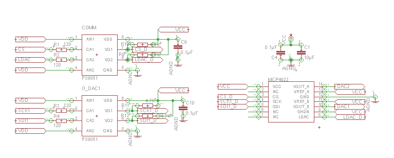
Hallo, wenn es Ihnen nicht stört werde ich meine Frage auf Englisch
schreiben. Ich kann Deutsch, aber nicht ganz gut und vielleicht kann ich
nicht alle Ihre tolle Ideen nicht richtig verstehen.

I'm working with the STM32F4Discovery Board and I'm using the SPI
communication to generate some signals with the DAC's MCP4922, that
works very well.

Now I have an analog and a digital ground fields which I have to
isolate, therefor I need to use the optocoupler PS9851-2 for every SPI
signal(MOSI, MISO, SS and SCK) my resistor at the input of the OK it's
120 ohms(the voltage of the µC it's 3v) and my pull up resistor it's
4,7Kohms(The Vcc it's 5v). I have been reading for a while but I'm
getting confused.

My questions are:
-Are the values that I calculated correct or plausible?

-Do I need to use in every output of the optocouplers a pull up
resistor?
I read that generally or always the open collector outputs need a pullup
resistor. But I have also read that a P.UP. resistor can generate a
delay in my signal if it has a high value.

And for the time those are my questions.

I'll add the diagram and the links to the datasheets.

http://www.cel.com/pdf/datasheets/ps9851.pdf
http://ww1.microchip.com/downloads/en/devicedoc/21897a.pdf

Thanks for your attention. Gracias de antemano compadres.

Miguel
Angehängte Dateien:
-

SigGen.PNG
6,1 KB
Wenn Englisch nicht für euch ist, ich kann mit Deutsch probieren. Aber
bitte, ich brauche ein bisschen Hilfe.
Meine Datenrate ist 20KHz. SDI ist MOSI, LDAC "ist" MISO (in diesen Fall
brauche ich nur zu synchronizieren die DACs und brauche ich kein MISO
Signal), CS ist SS und SCK ist CLK.
Miguel schrieb:
> Now I have an analog and a digital ground fields which I have to
> isolate, therefor I need to use the optocoupler PS9851-2 for every SPI
> signal(MOSI, MISO, SS and SCK) my resistor at the input of the OK it's
> 120 ohms(the voltage of the µC it's 3v) and my pull up resistor it's
> 4,7Kohms(The Vcc it's 5v). I have been reading for a while but I'm
> getting confused.
>
> My questions are:
> -Are the values that I calculated correct or plausible?


> -Do I need to use in every output of the optocouplers a pull up
> resistor?

Nein, weil im Datasheet geschrieben ist:
"The PS9851-1, -2 are optically coupled isolators containing GaAlAs LED
on the input side and a CMOS output IC
on the output side."


> I read that generally or always the open collector outputs need a pullup
> resistor. But I have also read that a P.UP. resistor can generate a
> delay in my signal if it has a high value.

Richtig.
Da wollte ich mir eigentlich nur die Vorschau ansehen und hab den
falschen Knopf gedrückt ...
Naja mache ich hier mal weiter...

schrieb im Beitrag #2730238:
> Now I have an analog and a digital ground fields which I have to
> isolate, therefor I need to use the optocoupler PS9851-2 for every SPI
> signal(MOSI, MISO, SS and SCK) my resistor at the input of the OK it's
> 120 ohms(the voltage of the µC it's 3v)

Laut Datenblatt hat die interne LED eine Spannung von rund 1.6V bei
10mA.
Du hast 3V am µC, also haben wir R = (3V-1.6V)/10mA = 140Ohm. Die
E12-Reihe sagt es gibt keinen mit 140Ohm und daher passen deine 120Ohm,
auf das bisschen kommt es nicht an.
Danke für deine Antwort Mr. Mo.,

ich habe das nicht bemerkt, das Ding ist dass ich irgendwo gelesen habe,
dass dieser OK Open Collector war, aber wenn in Datenblatt steht CMOS
output, dann es soll sein.

>Du hast 3V am µC, also haben wir R = (3V-1.6V)/10mA = 140Ohm.

Hmm es ist nicht so? R = (3V-1.6V)/0.010 A = 140 Ohm
und dann wie du gemacht hast mit der E12 Reihe habe ich 120 Ohm gewählt.
Miguel schrieb:
>>Du hast 3V am µC, also haben wir R = (3V-1.6V)/10mA = 140Ohm.
>
> Hmm es ist nicht so? R = (3V-1.6V)/0.010 A = 140 Ohm

Doch ist so. Dein Wert von 120Ohm ist ok.

> und dann wie du gemacht hast mit der E12 Reihe habe ich 120 Ohm gewählt.

Keine Ahnung wie die Reihen bei euch heissen, aber schau mal hier:
http://de.wikipedia.org/wiki/E-Reihe#Werte
bzw. die englische Variante, die aber nicht so eine schöne Tabelle hat:
http://en.wikipedia.org/wiki/Preferred_number#E_series:_Capacitors_and_resistors

Ich bin ausserdem davon ausgegangen, dass du mit normalen Widerständen
arbeitest. Diese sind meistens E12 mit 10% Toleranz.

Wenn du in die Tabelle in die Reihe von E12 schaust, sieht du das es
keinen Wert zwischen 1,2 und 1,5 gibt. Daher musst du dich für einen
entscheiden,also 120Ohm oder 150Ohm.
Ach so!, sorry haha ich habe mich verwirrt zwischen das "O" und das Null
und stimmt jetzt alles passt. Ja, ich habe an die E12 Reihe nachgeguckt
und jetzt verstehe ich besser.

Vielen Dank für deine Hilfe.
Instead of optocouplers, a digital isolator, such as the ADUM1401 might
be interesting:
http://www.analog.com/en/interface/digital-isolators/adum1401/products/product.html
Bitte melde dich an um einen Beitrag zu schreiben. Anmeldung ist kostenlos und dauert nur eine Minute.
Bestehender Account
Schon ein Account bei Google/GoogleMail? Keine Anmeldung erforderlich!
Mit Google-Account einloggen
Mit Google-Account einloggen
Noch kein Account? Hier anmelden.