1 | #ifndef pins_h
|
2 | #define pins_h
|
3 |
|
4 | // Pin assignments
|
5 | // DS1307 - RTC (wire library)
|
6 | #define PIN_RTC_SDA A4
|
7 | #define PIN_RTC_SCL A5
|
8 |
|
9 | // 74HC595 - LED driver
|
10 | #define PIN_LEDS_DS 8
|
11 | #define PIN_LEDS_ST 9
|
12 | #define PIN_LEDS_SH 10
|
13 |
|
14 | // 74HC165 - Switch driver
|
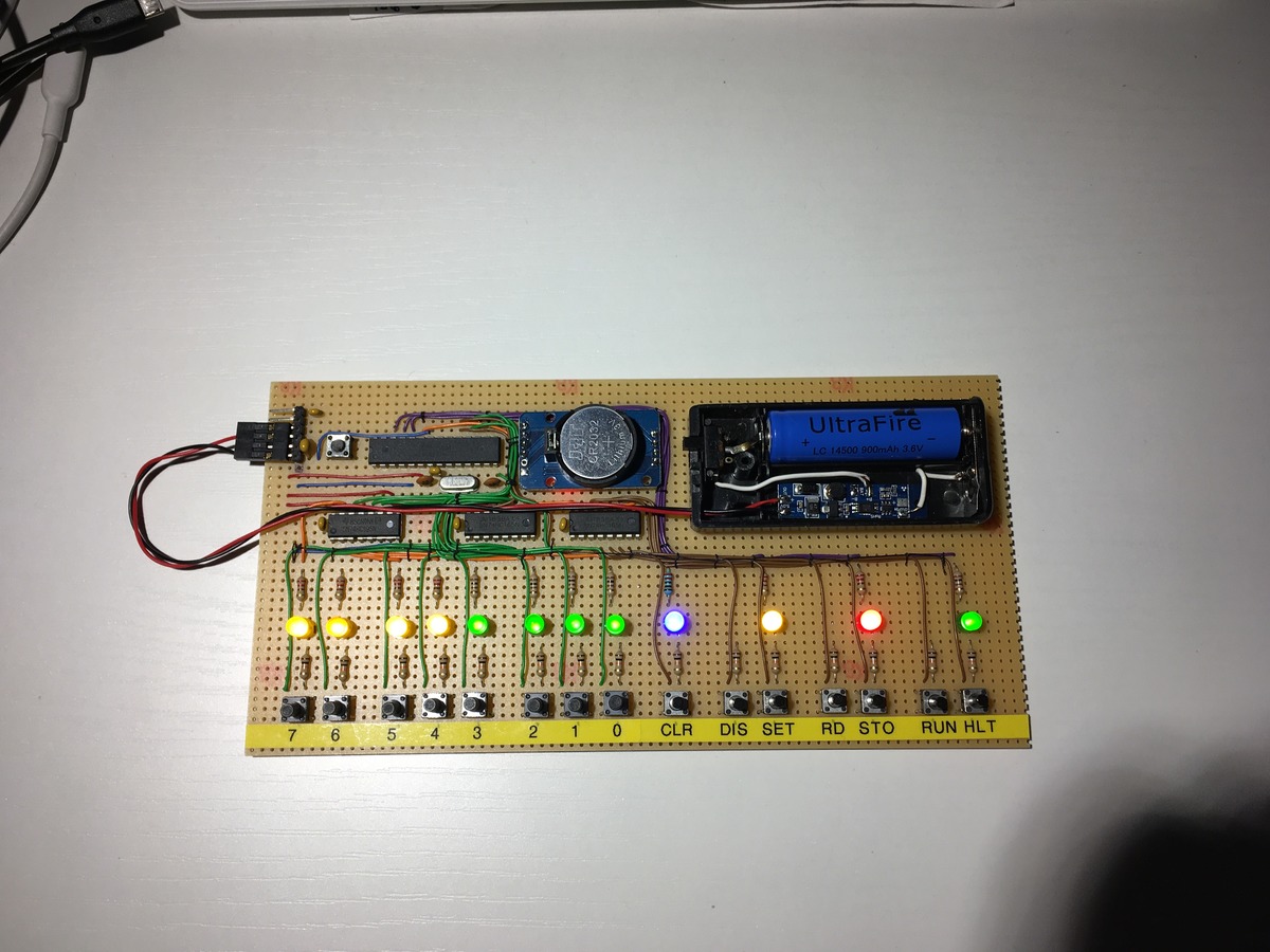
15 | #define PIN_BTN_Q7 A0
|
16 | #define PIN_BTN_CP 13
|
17 | #define PIN_BTN_PL 12
|
18 |
|
19 | // LEDS - direct connection
|
20 | #define PIN_LED_INP A1
|
21 | #define PIN_LED_ADDR A2
|
22 | #define PIN_LED_MEM A3
|
23 | #define PIN_LED_RUN_PWM 11
|
24 |
|
25 | /*********************************************************
|
26 | This is a *SCHEMATIC*
|
27 | Pins not listed are unused/floating.
|
28 | Component list:
|
29 | ATMega328, DS1307, 74HC595, 74HC165 (x2),
|
30 | LED (x12), Push-button normally open (x15),
|
31 | Resistor 220 Ohm (x12), Resistor 10k Ohm (x15),
|
32 | 16MHz crystal.
|
33 | "KENBAK-uino" - Mark Wilson, 2011
|
34 | +-----------+
|
35 | | 328 |
|
36 | <USB>--[+5V]---+Vcc PWM11+-------<LED11 "RUN">
|
37 | <USB>--[+5V]---+AVcc A3+-------<LED10 "MEM">
|
38 | <USB>--[GND]---+Gnd(22) A2+-------<LED9 "ADDR">
|
39 | <USB>--[GND]---+Gnd(8) A1+-------<LED8 "INP">
|
40 | <USB>---[TX]---+TX |
|
41 | <USB>---[RX]---+RX | +-----------+
|
42 | | | | 595 |
|
43 | [XTAL1]----+XT1 10+--------+SH(11) Q0+----<LED0 "Bit0">
|
44 | [XTAL2]----+XT2 9+--------+ST(12) Q1+----<LED1 "Bit1">
|
45 | | 8+--------+DS(14) Q2+----<LED2 "Bit2">
|
46 | | | [+5V]-+Vcc(16) Q3+----<LED3 "Bit3">
|
47 | | | [GND]-+Gnd(8) Q4+----<LED4 "Bit4">
|
48 | | | [+5V]-+MR(10) Q5+----<LED5 "Bit5">
|
49 | | | [GND]-+OE(13) Q6+----<LED6 "Bit6">
|
50 | | | | Q7+----<LED7 "Bit7">
|
51 | | | +-----------+
|
52 | +------+ | |
|
53 | | 1307 | | | +-----------+
|
54 | | SDA+---------+A5 | | 165-1 | **Note the order!**
|
55 | | SCL+---------+A4 A0+-------------+Q7(9) D0+----<SW0 "Bit0">
|
56 | | Vcc+-[+5V] | 13+-----+-------+CP(2) D1+----<SW1 "Bit1">
|
57 | | Gnd+-[GND] | 12+--+ | | D2+----<SW2 "Bit6">
|
58 | +------+ +-----------+ +--|-------+PL(1) D3+----<SW3 "Bit7">
|
59 | | | [GND]-+Gnd(8) D4+----<SW4 "Bit4">
|
60 | | | [GND]-+CE(15) D5+----<SW5 "Bit5">
|
61 | | | [+5V]-+Vcc(16) D6+----<SW6 "Bit2">
|
62 | | | +--+DS(10) D7+----<SW7 "Bit3">
|
63 | | | | +-----------+
|
64 | | | |
|
65 | | | |
|
66 | | | | +-----------+
|
67 | | | | | 165-2 | **Note the order!** (corrected May 2014)
|
68 | | | +--+Q7(9) D0+----<SW8 "STOP">
|
69 | | +-------+CP(2) D1+----<SW9 "STRT">
|
70 | | | D2+----[GND] (SW15 is unused)
|
71 | +----------+PL(1) D3+----<SW10 "CLR">
|
72 | [GND]-+Gnd(8) D4+----<SW11 "DISP">
|
73 | [GND]-+CE(15) D5+----<SW12 "SET">
|
74 | [+5V]-+Vcc(16) D6+----<SW13 "READ">
|
75 | | D7+----<SW14 "STOR">
|
76 | +-----------+
|
77 |
|
78 |
|
79 | where:
|
80 | _ (Push-button, Normally Open)
|
81 | + +
|
82 | --<SWx> is --+--+ +----[+5V]
|
83 | |
|
84 | +-[10kR]--[GND]
|
85 |
|
86 | --<LEDx> is --[220R]--[LED]--[GND]
|
87 |
|
88 | **Note the order!**
|
89 | This reflects the order I wired my switches to '165 pins.
|
90 | You are free to change this to match the physical arrangement of the buttons,
|
91 | BUT you will need to also change Buttons::m_pMap[] to match.
|
92 |
|
93 | *********************************************************/
|
94 | #endif
|