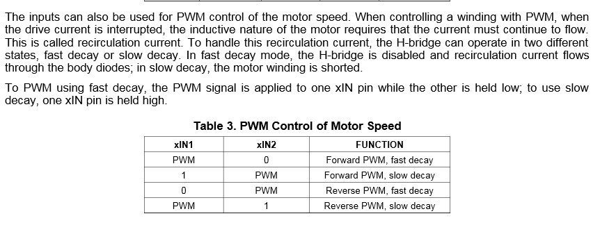
Guten Tag,

ich habe folgendes Problem:

Ich möchte zwei DC Motoren mit oben genanntem Chip,
TI DRV8833 betriben (Datenblatt habe ich beigefügt).

Das ganze soll über einen Mikrocontroller angesteuer werden und die
Geschwindigkeit der Motoren soll per PWM gesteuert werden. Pro Motor ein
PWM Signal.

Mein Problem ist nun folgendes:

In Tabelle 8 Seite 3 Datenblatt steht die Pinbelegung für die versch.
Auslaufmöglichkeiten. (Siehe Screenshot)

Ich möchte den Motor vorwärts und rücwärts auf dieselbe Weise bremsen.
Laut dieser Tabelle müsste ich aber nun den PWM immer auf den anderen
Anschluss legen?

Gibt es hier eine andere Möglichkeit? Es kann doch nicht sein, dass ich
den PWM Pin wechseln muss, bzw. 4 Pins für PWM verwenden muss.

Vielen Dank.
Angehängte Dateien:
-

pwm_screen.PNG
19 KB
Du brauchst gar nix wechseln.
Wenn Du es möchtest kannst DU PWM an AIn1, AIn2 und BIn1 und BIn2
legen.....


Eben nach dem Schema in Bild 2!

Gruß T.
Warum muss es dieser Chip sein?
Evtl. gibt es ja einen, der nur einen PWM- Input benötigt und Du für die
Umschaltung sorgen kannst?

Wenn es aber dieser sein muss, dann kannst Du doch die Logik ziemlich
einfach mit standard TTL - Technik aufbauen!

Gruß T.
seems to be so: both input-pins should be able to output a PWM-signal
http://ebldc.com/?p=264:

EBLDC: That definitely sounds easy! So I can control direction of
rotation by selecting output polarity. But what if I want to control the
speed? This is a must when driving a DC motor, right?

DRV8833: But of course! This can be easily done as well since my inputs
can be PWM’d. Just apply a PWM signal to the driving input and my
outputs will follow. For example, if you make AIN1 HI and AIN2 is being
PWM’sd, then current will flow from AOUT1 to AOUT2 when the PWM signal
is in the OFF state and I will enter slow decay mode when the PWM signal
is at the ON state. You can do it backwards to. Make AIN1 LO and then I
will conduct when AIN2 is HI and enter slow decay when AIN2 is LO.

EBLDC: Intriguing… So it seems we can only do slow decay then?

DRV8833: Ehh… That is not true actually! You can do fast decay if
instead of a single PWM you have two of them. If both AIN1 and AIN2 are
being PWM’d in such a fashion that they are always opposing each other,
then I will be entering fast decay at all times.
Thanks a lot.

I thought i would be wrong but it seems that i will ned two pwm outputs
to controll this chip.
Stefan B. schrieb:
> Thanks a lot.
>
> I thought i would be wrong but it seems that i will ned two pwm outputs
> to controll this chip.

Lies das Datenblatt und VERSTEHE auch was drin steht. Wenn dir der IC zu
komplex ist, dann nimm einen einfacheren.
Ansonsten wenn du es nicht besser weißt: es gibt auch Logikbausteine
(AND) mit denen kann man da was machen ("pwm and logic") dann spart man
sich einen pwm Pin ...
Bitte melde dich an um einen Beitrag zu schreiben. Anmeldung ist kostenlos und dauert nur eine Minute.
Bestehender Account
Schon ein Account bei Google/GoogleMail? Keine Anmeldung erforderlich!
Mit Google-Account einloggen
Mit Google-Account einloggen
Noch kein Account? Hier anmelden.