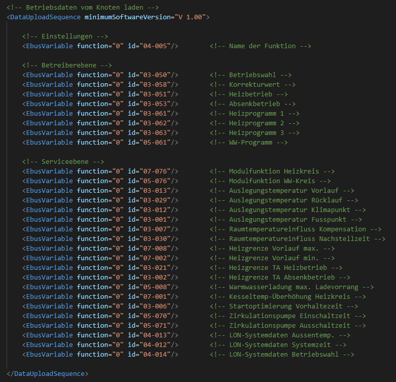
Nur die letzten 4 sind welche aus dem library manager.
Die anderen sind alle Teil des ESP32 v1.0.6
https://dl.espressif.com/dl/package_esp32_index.json
Funktioniert!
Danke an alle für die Hilfe!!

Ich konnte alles kompilieren und jetzt auf den Chip flashen.
Das Problem war scheinbar, dass ich die Arduino Version 1.8.19 aus dem
Microsoft Store verwendet habe, anstatt die Version 1.8.1.

Mit der 1.8.1 funktioniert jetzt alles!

Wenn ich die restliche Hardware aufgebaut habe, kann ich das dann
"einfach" an die 2 Lon-Verbinder verkabeln, oder muss ich das noch wie
die Windhager-Module irgendwie "binden"?
Du kannst dich einfach auf den LON hängen, binden muss man hier nichts.

Stelle aber bitte vorher sicher, dass dein GND bei deinem ESP und deiner
Heizung verbunden ist.
Nicht dass dummerweise die GNDs 200V auseinander liegen :)
Johannes K. schrieb:
> Wenn ich die restliche Hardware aufgebaut habe, kann ich das dann
> "einfach" an die 2 Lon-Verbinder verkabeln, oder muss ich das noch wie
> die Windhager-Module irgendwie "binden"?

I am running with an M5Stack ESP32 module and only a MAXIM RS485 IC
connected directly to the LON-bus. The M5Stack/ESP32 is powered from a
plain USB-power adapter.

In my case I have NOT connected ground between my ESp32 setup and the
burner. Only the differential RS485 LON-bus.

It works great. A simple RS485 adapter like the one below can easily be
used. All you need is the ESP32 module and the RS485 adapter and that's
it.

https://www.amazon.de/-/en/DollaTek-MAX485-Module-RS-485-Development/dp/B07DK4QG6H/ref=sr_1_18?crid=2NK01FS6P0E6S&keywords=ICQUANZX+MAX485%2FRS485&qid=1643754798&sprefix=icquanzx+max485%2Frs485%2Caps%2C80&sr=8-18
Well, in theory this works well.
A faulty USB power supply fried a microcontroller in an other setup,
because it wasn't isolated well enough.

And when connecting something to my central heater, i'd do my best that
this won't happen here as well ;)

So this was thought as a security measure hint except you are aware that
your
transceiver and your circiuit is isolated for the maximum possible
voltage difference.
Angehängte Dateien:
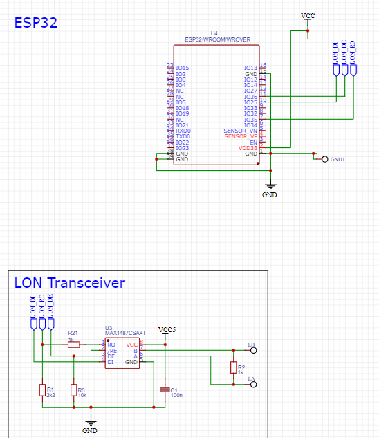
Hallo,

ich konnte es heute ausprobieren, leider war ich nicht so erfolgreich.
In meinem PMX gibt es eine Klemme für GND, LON+ und LON-, da habe ich
mich parallel zur Pellets-Saugeinheit draufgehangen.

Leider kommt im Seriell-Monitor ausser den WIFI und Co. Meldungen nichts
vom LON an.
Die Verkabelung mit dem MAX487 habe ich gefühlt 100x kontrolliert.

Anbei der Schaltplan. Ich hatte mir gedacht, ich schmeiß alles raus, was
ich gerade "noch" nicht brauche. Die Pin's musste ich wie folgt ändern,
da ich dieses Board hier verwende:

https://www.amazon.de/gp/product/B08TBPBJGV/ref=ppx_yo_dt_b_asin_title_o01_s00?ie=UTF8&psc=1

#define LON_RX    17
#define LON_TX    16
#define LON_TX_EN 26

Oder fehlt da ich Schaltplan jetzt noch was, dass ich einen PIN auf
Ground oder so ziehen muss?
Servus,

schaut eigentlich sinnvoll aus.

1. die Polarität vom LON passt?
2. die gewählten Pins werden sicher nicht von etwas anderem verwendet?
(1-wire?, Relais, ...)
3. Bei dem Board liegt wirklich der GPIO da an, wo du denkst? :D

In dem Fall ist erst mal nur der RO-Pin notwendig.
Magst da mal mit dem Oszi messen?

Gruß,
Georg
Hallo Georg,

Polarität vom Lon hab ich gecheckt, die passt.
Auf dem Modul steht hinten IO26, IO16 und IO17 drauf.
Das muss ich doch dann so ins Programm eingeben, oder?

Oszi messen ist schwierig, ich kann nur mit einem Multimeter dienen ;-)

Ich habe jetzt mal nochmal alles von GitHub runtergeladen und neu
kompiliert und hochgeladen. Auch den MAX487 habe ich schon in einen
anderen getauscht. Aber keine Änderung...

Welch .ino-Dateien müsste ich eigentlich kompilieren lassen?
Theoretisch könnte ich ja LED, Relay usw. weglassen, oder? Ich habe bis
jetzt immer die MESWIFI in Arduino geöffnet und dann die anderen INOs
mit in Arduino aufgemacht, dass ich 12 Tabs hatte. Und dann alles
kompiliert und auf den Chip.

Gruß
Johannes

Ausgabe aus dem seriell-Monitor:

[i] Starting
[i]   Setup WiFi
[WiFi] Connecting...
[i]   Setup OTA
[i]   Setup Time
[i]   Setup SPIFFS
[i]   Setup LON bus
[i] read status from SPIFFS
[i]   Setup MQTT
[i]   Setup Relays
[REL] setting 0 to OFF
[REL] setting 1 to OFF
Setup done
[REL] setting 0 to ON
[REL] setting 1 to ON
[REL] setting 0 to OFF in 2000 ms
[REL] setting 1 to OFF in 5000 ms
[i] cyclic status save
[NTP] Sending request
[REL] setting 0 to OFF
[WiFi] Connected, IP address: 192.168.0.40
[NTP] The time is: 18:32:29
[REL] setting 1 to OFF
Johannes K. schrieb:
> Oder fehlt da ich Schaltplan jetzt noch was, dass ich einen PIN auf
> Ground oder so ziehen muss?

You have connected /RE with GND. This is incorrect. Connect /RE with DE,
also replace R2 with 120ohm.
Mit welcher Spannung betreibst du den MAX487?
Der Teiler passt zur Spannung?

Ich würde langsam hergehen und die anliegenden Pegel messen bzw mal
manuell setzen und im ESP32 schauen, ob der Pegel auch wirklich ankommt.
(per digitalRead und Serial.printf)
z.B. den MAX abklemmen und z.B. 5V an den Spannungsteiler anlegen.
Hallo,

ich habe den Vorschlag von Thomas ausprobiert, leider keine Änderung.
Kein Output.

Die Spannung kommt im Moment direkt aus meinem Laptop vom USB-Port in
das ESP-Board. Von da aus weiter zum MAX487.
Gemessen habe ich gerade 4,6V am MAX.
Auch mit einem USB-Netzteil keine Änderung. 4,55V

Gruß
Johannes
Johannes,

can you copy paste the part of the code where you assign the GPIO's so
we can see what it looks like.

Mine currently looks like this.
1 | #define LON_RX 16 // GPIO16 is for Commu, GPIO35 is for my breadboard |
2 | #define LON_TX_EN 17 // GPIO17 is for Commu, GPIO2 is for my breadboard |
3 | #define LON_TX 5 // GPIO 5 is for both Commu and my breadboard |
This his how you should have connected it then,
1 | #define LON_RX 17 // Connects to RO on MAX487 |
2 | #define LON_TX 16 // Connects to DI on MAX487 |
3 | #define LON_TX_EN 26 // Connects to DE + /RI on MAX487 |
BUT!!!!

There is no GPIO16 and 17 in the schematic above! So, it is not
possible! (?)
GPIO16 and 17 is also used for UART2 in some ESP-modules.

Which pins on the module did you connect to, and exactly which module
are you using?
Hello,

this was "in between", sorry for the confusion.

At the moment i have my setup like this:

#define LON_RX    26    // Connects to RO on MAX487
#define LON_TX    18    // Connects to DI on MAX487
#define LON_TX_EN 19    // Connects to DE + /RI on MAX487

Modul is excactly this one:
https://www.amazon.de/gp/product/B08TBPBJGV/ref=ppx_yo_dt_b_asin_title_o01_s00?ie=UTF8&psc=1

Code:
#define LON_RX    26
#define LON_TX    18
#define LON_TX_EN 19

Thanks for your help!
Johannes
Also, if you are using a breadboard, make sure you have a buffer
capacitor close to the MAX487, it is required for proper function! I
forgot it on my first setup and I lost 50% of all packets due to that.

Ok, many of the pins on the EPS32 has many different uses and can
sometimes be troublesome to use.

You could try the same setup as I have used that worked fine.

#define LON_RX    35   // Connects to RO on MAX487
#define LON_TX    5    // Connects to DI on MAX487
#define LON_TX_EN 2    // Connects to DE + /RE on MAX487
Angehängte Dateien:
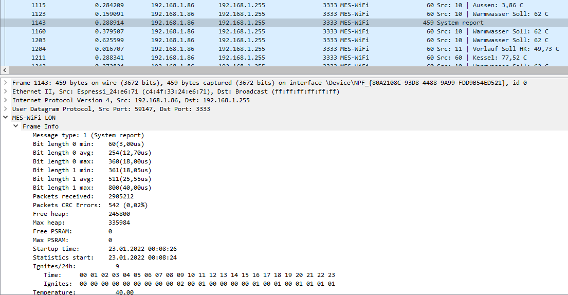
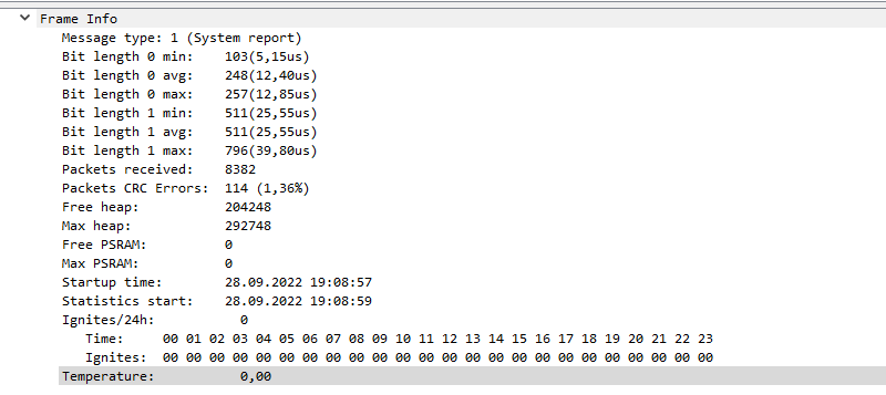
To receive, you only need the RO line of the transceiver, so please
focus on that first.

 - double-check LON polarity (or try reversing, to check if it changes
things)
 - measure the RO line with your multimeter. is it static 0V or 5V? ->
bad
 - does it toggle irregulary? -> good
 - or - do you see some voltage when you use AC measurement? -> good
 - also a good idea to use a different pin. be aware that <13 is tricky
and > 33 is input only ->
https://randomnerdtutorials.com/esp32-pinout-reference-gpios/
 - yeah, that bypass cap is a good point, but then you still should see
some packets on UDP 3333 in wireshark
 - what do the "System report" packets tell you?
Magst vielleicht ein, zwei Fotos vom Breadboard reinstellen? Vielleicht
hilft das.

lg Michael
Angehängte Dateien:
-

20220202_210315.jpg
240 KB -

20220202_210301.jpg
240 KB
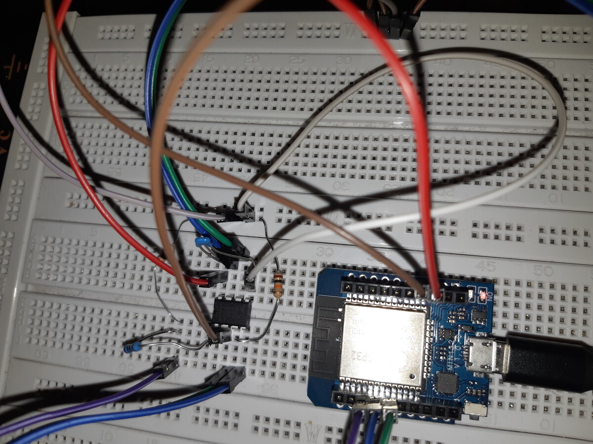
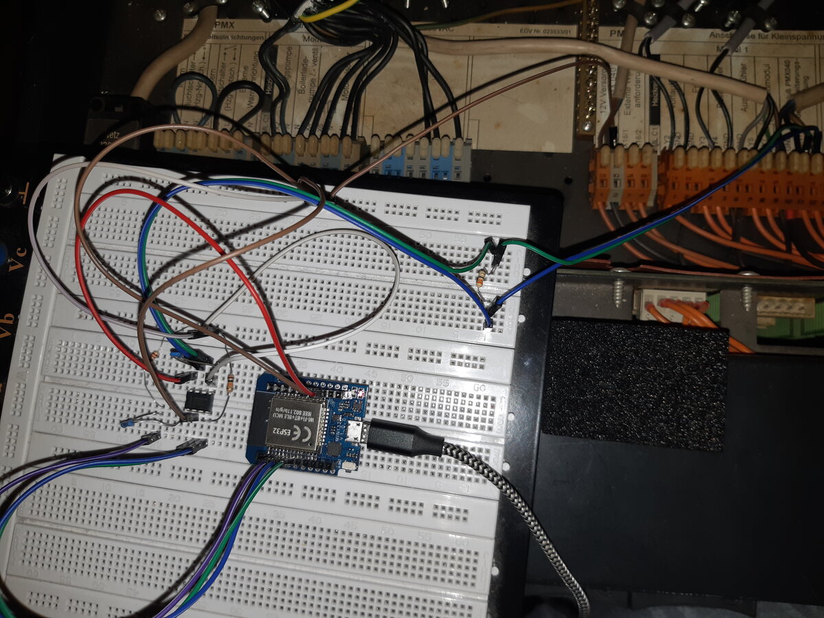
Hallo,

anbei 2 Bilder, weiß aber nicht, ob man darauf was erkennen kann.
Spannung zwischen RO und GND sind im Gleichspannungsmodus 0 - 66mV.
Im Wechselstrommodus bleibt's bei 0V.
Vielleicht ist auch mein Multimeter zu ungenau.

Ich probiere jetzt mal noch einen anderen PIN als den 26er für RO aus.

Gruß
Johannes
Johannes K. schrieb:
> Ich probiere jetzt mal noch einen anderen PIN als den 26er für RO aus.

23er Pin probiert --> gleiches Verhalten. bleibt bei der Zeit stehen.
> Spannung zwischen RO und GND sind im Gleichspannungsmodus 0 - 66mV.
> Im Wechselstrommodus bleibt's bei 0V.

Zwar ist das eher Kategorie "Spannung mit nassem Finger schätzen", aber
es deutet drauf hin, dass dein Transceiver nix sieht.
Was sagt dein Multimeter an den LON-Leitungen, was da anliegt?
Masse gegen LON+  --> 2,27V
Masse gegen LON-  --> 2,27V
LON- gegen LON+   --> 0V
Wenn sich da auf den Leitungen nichts ändert, (AC mode, LON+ <-> LON-)
würde ich skeptisch werden.
hab nochmal gemessen,
springt rum, zwischen 0 und 0,24V im AC Mode.

Was sollte es denn sein?

Irgendwie muss das aber passen, sonst würde meine Pelletssaugerei nicht
funktionieren...
Okay, wenn sich hier "etwas tut", dann könnte die Basis schon passen.
Aber ganz ehrlich - ohne Oszi ist das hier besseres Schätzen.

Wo hast du den LON abgegriffen? Wie lang sind die Leitungen?
Kabel sind ca. je 15 - 20cm lang.
Der Anschluss ist für den Pelletssauger, direkt im Heizkessel an der 1.
Klemme, wo das UML C1 draufsteckt.

Würde sowas hier reichen, um was zu "sehen"?

https://www.amazon.de/Quimat-Digital-Oszilloskop-Maschine-montiert/dp/B077CZVZTJ/ref=sr_1_7?keywords=oszilloskop&qid=1643839033&refinements=p_76%3A419122031&rnid=419121031&rps=1&sprefix=oszilo%2Caps%2C86&sr=8-7
Bin kein Messgeräte-Profi, aber ich hätte mal gesagt, dass das von der
Bandbreite ausreichend ist.
You MUST add a much larger capacitor between VCC and GND close to the
MAX487!!!!

Before you do that, it is pointless to fault find anything else.

You should preferably put 100uF.
You can easily turn the ESP32 into a simple logic analyzer, and the way
things are right now, that or some LED's can get you a long way ;)

But first, a buffer capacitor!
Was mir grad so kommt, beim LON sollte doch der LON+ bei 2,7V liegen?
LON- liegt bei so 2.3V
->
https://store.chipkin.com/articles/rs485-what-are-possible-rs485-polarity-issues
Hallo,

ich Schaltplan stand was von 100nF, den hatte ich drin.
Hab jetzt auf einen 100uF gewechselt, aber immer noch keine
Kommunikation.

Außerdem habe ich noch ein anderes Multimeter genommen, und da ist auf
beiden LON-Klemmen gegen Masse 2,4V drauf. Kann ungenau sein, aber
beides mal exakt das Gleiche.

Gruß
Johannes
Ich habe jetzt auch an meiner Anlage gemessen.
Beide LON haben bei mir 2.20 V und bei starker Aktivität auf dem Bus
sehe ich ~10mV als AC mit meinem Fluke.

Daher besser warten bis dein Oszi da ist.
Angehängte Dateien:
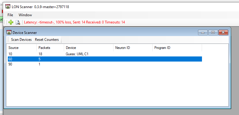
ich glaube, wir müssen wo anders suchen ;-)

Die Ausgabe im Serial-Monitor bleibt immer noch an der Zeit stehen.
Allerdings habe ich gerade mal den LON-Scanner angeworfen und auf einmal
kommen da Daten an ?!?!?

Es wird zwar immer noch nichts im SerialMOnitor oder MQTT ausgegeben,
aber prinzipiell scheint das Lesen zu funktionieren...  :-)

Gruß
Johannes
Hallo,
ich habe mal den Quellcode in GitHub angeschaut, da ist "MQTT_setup"
auskommentiert?
Ein einkommentieren bringt aber auch nichts, da es scheinbar nirgends
einen "Connect" gibt?
Gab's Probleme mit MQTT?

Gruß
Johannes
Nein, MQTT funktioniert perfekt, bei mir mit Mosquitto.

du musst natürlich die MQTT.ino anpassen (Server etc.) als auch in der
MESWiFi.ino sowohl mqtt_setup() als auch mqtt_loop() aktivieren.

lg Michael
Ja, natürlich ;-)
mqtt_loop() auskommentieren, den Rest hatte ich schon.

Jetzt sehe ich was im Serial-Monitor und auf dem MQTT-Explorer sind auch
die Werte drauf!!! :-)

Vielen Dank an alle für die Mithilfe!!
Das war eigentlich schon das Ganze "Problem"...

Danke nochmal!!
Johannes
ich hab schon länger einen Grund für den Kauf eines Oszis gesucht ;-)
heißt?

auch würde mich interessieren, wie ich zusätzliche Datenfelder aus dem
LON-Scanner auf mein MQTT bekomme. Steht das irgendwo?
heisst: Ich muss das fixen. da steht nicht WVF oben in den Textfeldern.

Wenn du mehr ins MQTT schaufeln willst, musst den arduino source in der
LON.ino anpassen.
Ist aber nicht so wirklich sauber.
Ich hab das insbesondere für WVF deutlich erweitert - kann ich gerne zur
Verfügung stellen.

Wobei ich immer noch am Lernen bin, wie mein UML C1 und WVF mit meiner
Gastherme zusammenspielen. Die sehe ich nämlich im Unterschied bei
Georgs PMX nicht am LON-Bus.

Ich fürchte ich muss mir den eBus auch noch ansehen.

lg Michael
den PMX Kessel sehe ich auch nicht, auch nicht im LON-Scan.
Könnte daran liegen, dass mein Kessel beim Start immer Version 2.60
zeigt?

Wenn du mir deine LON.ino zur Verfügung stellen könntest, das wäre
super!
Ich habe auch UML C1 und WVF in Betrieb.

Danke,
Johannes
Angehängte Dateien:
-

Scan.png
6,8 KB
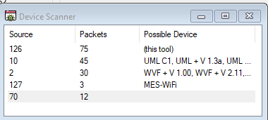
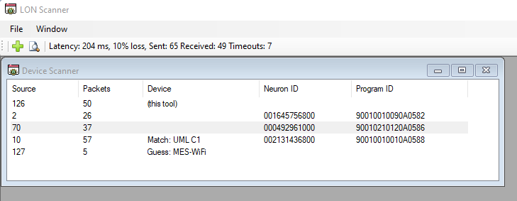
siehe Anhang.
Kann es sein, dass die 70 dieses Raumbediengerät ist, das bei mir im
Wohnzimmer hängt?
generell:
https://github.com/g3gg0/LonScan/releases/

konkret die letzte:
https://github.com/g3gg0/LonScan/releases/tag/v0.3.5
Ok ändert nix. Schad.
Dann hab ich die genaue version nicht als info-file.

Falls jemand alte XIF files hat, gerne melden.
Angehängte Dateien:
Anbei mein Scan-Ergebnis.

Im Regelbetrieb hab ich knapp über 0% CRC Fehler - wenn ich das Tool
verwende, geht der Wert stark rauf. Ich hoffe, dass da das hoffentlich
bald neue Setup Besserung bringt :)
> Wenn du mir deine LON.ino zur Verfügung stellen könntest, das wäre
> super!
> Ich habe auch UML C1 und WVF in Betrieb.

gerne, anbei! Auch die MQTT.INO

Es fehlt dort noch das ganze Handling von noch nicht abgefragten, sprich
noch frisch initialisierten Variablen.
I have been using the M5Stack Core module to run this.

Tonight I wanted to install on a Core2 module, and then I ended up with
the
1 | error: 'PERIPH_RMT_MODULE' was not declared in this scope |
To overcome this problem, I replaced an include in LON_RMT_rx.ino
1 | //include "driver/rmt.h" |
2 | #include "driver/periph_ctrl.h" |
Perhaps the same change will fix the same issue occuring when updating
IDE from 1.8.1 to 1.8.19
Johannes K. schrieb:
> <screenshot>

Ich habe in dem screenshot gesehen, dass der version-string falsch
interpretiert wird.
Könntest du mit der v0.3.7 die "Application" deiner WVF dumpen und mir
zuschicken?
https://github.com/g3gg0/LonScan/releases/tag/v0.3.7

So könnte ich mir genauer anschauen was an deiner version anders ist.

mailadresse:  mes ÄT g3gg0 PUNKT de

Gruß,
Georg
Angehängte Dateien:
-

IMG_5224.jpg
240 KB -

IMG_5225.jpg
240 KB -

IMG_5226.jpg
240 KB -

IMG_5228.jpg
240 KB -

IMG_5230.jpg
230 KB -

IMG_5232.jpg
230 KB
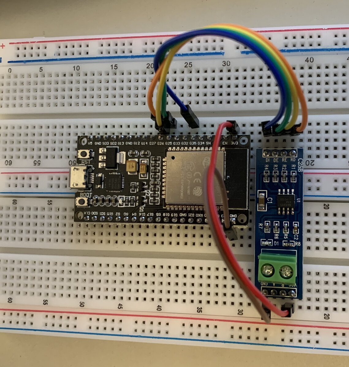
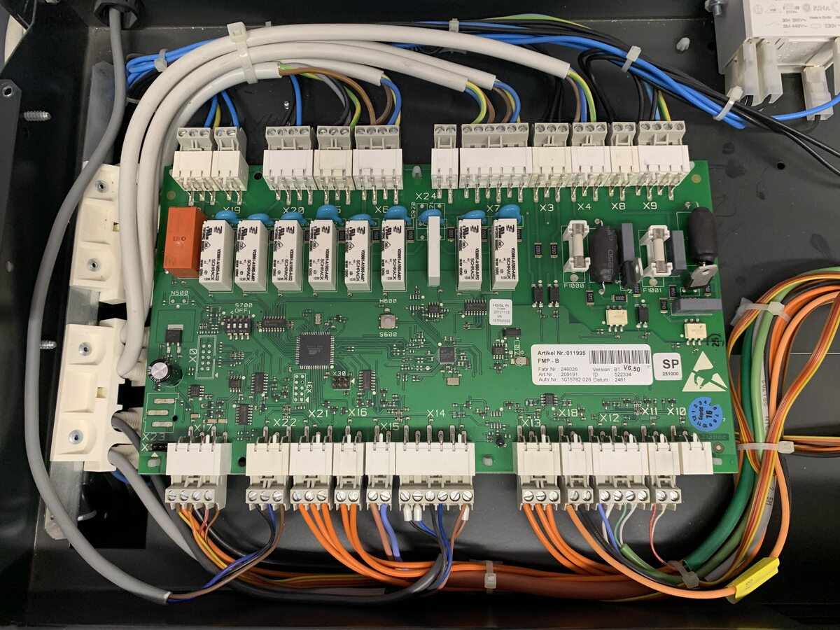
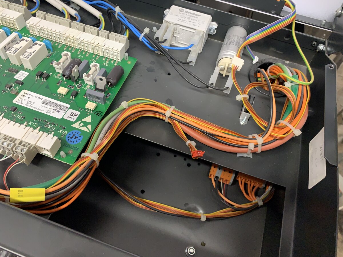
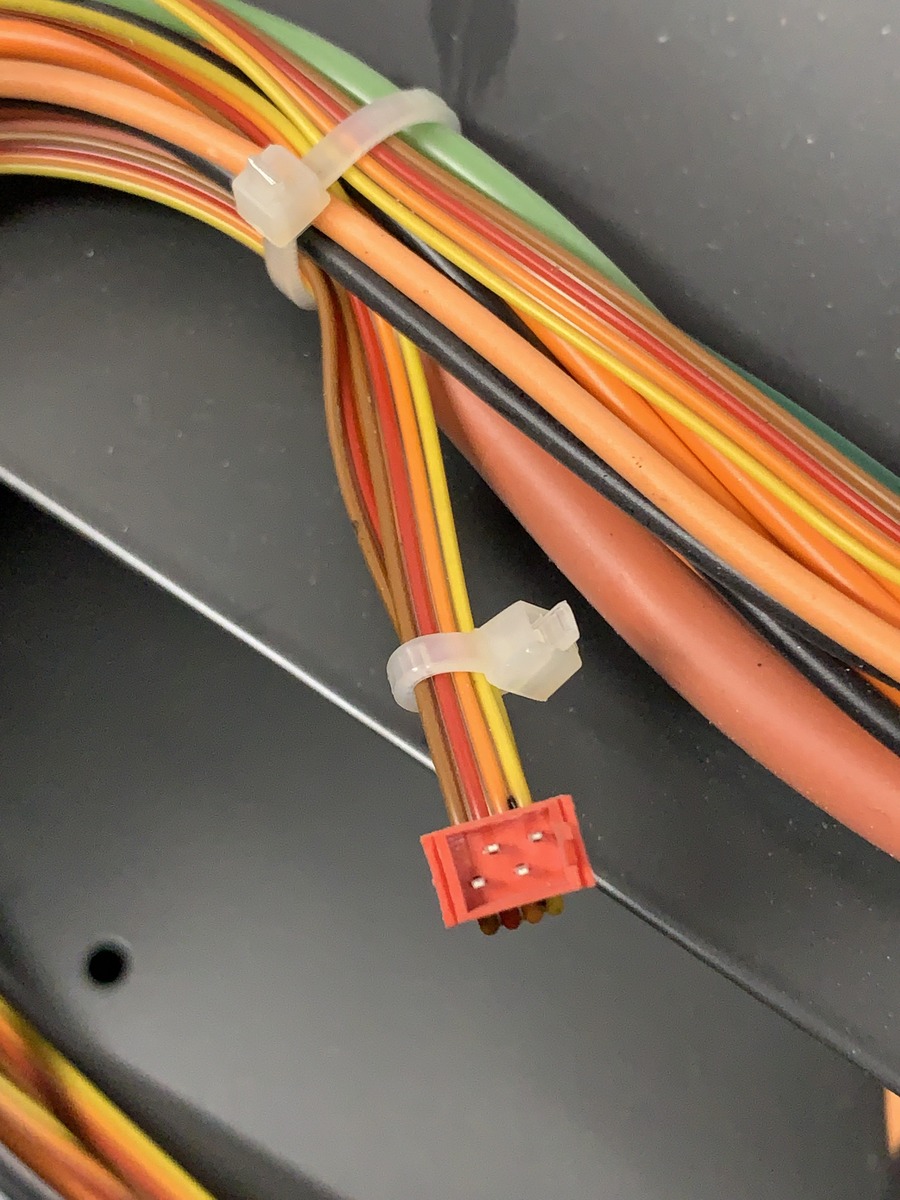
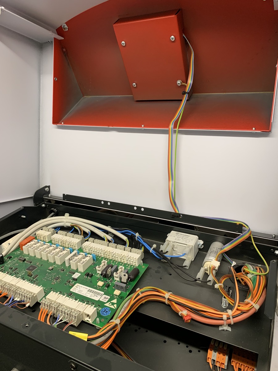
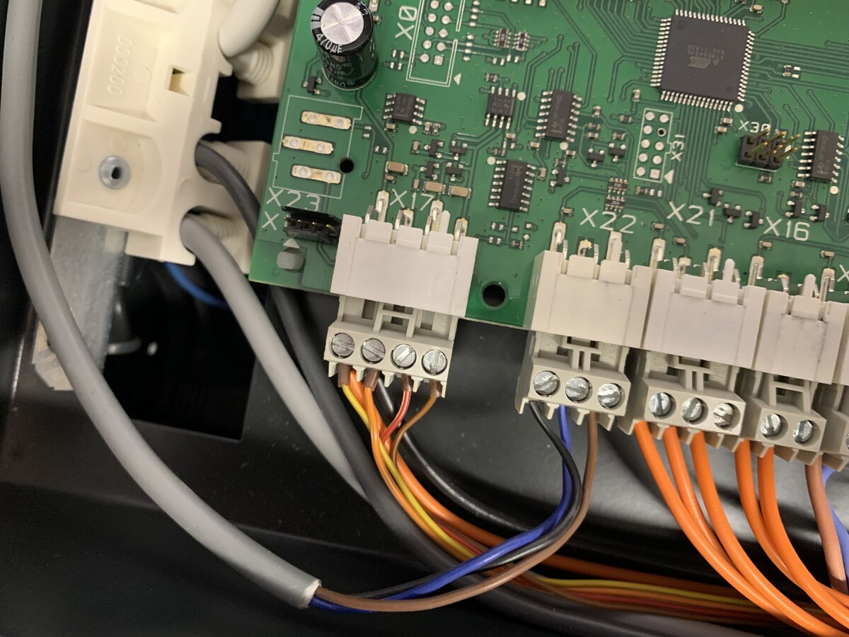
Hallo zusammen,

ich habe einen Solvis Lino 3. Der ist wohl baugleich mit einem Windhager
BioWin BWE 150 Exklusiv. Ich würde den gerne mit Georgs Lösung auslesen.
Ich versuche mir das aus dem Thread zu erschließen, leider gelingt es
mir nicht vollständig. Vielleicht könnt Ihr mir helfen das zum fliegen
zu bekommen:

Ich habe einen ESP-WROOM-32 und ein C25B RS485 Modul. Ich habe das so
auf dem Breadboard aufgebaut:

RO -> G26
RE/DE -> G25
DI -> G35
VCC -> 3,3V
GND -> GND

Ist es richtig, den Aufbau nun wie folgt an den LON-Bus zu hängen?
A -> LON+
B -> LON-

Ist es egal wo ich das reinhänge? Ich verstehe das mit dem Widerstand R7
nicht. Darf der immer da sein und MUSS am Ende vorhanden ein. Oder muss
der entfernt werden, wenn ich im Bus hänge.

Bus-Kabel

Im Installateur-Handbuch S.42 habe ich die Belegung der Klemme X17
gefunden:
1: 12V (Gelb)
2: GND (Orange)
3: LON+ (Rot)
4: LON- (Braun)

Von dort läuft ein "Bus-Kabel" von der Reglerplatine zum Bedienpanel.
Kenn ihr diese roten Stecker, da könnte man sich ja schön einklinken,
wenn man so einen als Female-Stecker bekommt. Alternativ gibt es am Bus
auch einen Diagnosestecker.

Danke vorab für die Hilfe.
Ich hoffe die Gxx sind die GPIOxx.
Wenn ja, dann sollte es so sein:

RO (RX) -> G35
RE/DE (TX_EN) -> G26
DI (TX) -> G25

Referenz: https://github.com/g3gg0/MESWiFi/blob/master/LON.ino#L15
#define LON_RX    35
#define LON_TX    25
#define LON_TX_EN 26

Terminator: Kannst so drin lassen, sollte nicht stören.
Angehängte Dateien:
Hallo Georg,

danke für die Antwort. Ich habe die Hardware nun entsprechend aufgebaut
und den ESP32 geflasht.
1 | [i] SDK: 'v3.3.5-1-g85c43024c' |
2 | [i] CPU Speed: 240 MHz |
3 | [i] Chip Id: 9A12CFA4 |
4 | [i] Flash Mode: 00000002 |
5 | [i] Flash Size: 00400000 |
6 | [i] Flash Speed: 80 MHz |
7 | [i] Heap 312232/338720 |
8 | [i] SPIRam 0/0 |
9 | |
10 | |
11 | [i] Starting |
12 | [i] Setup WiFi |
13 | [WiFi] Connecting... |
14 | [i] Setup OTA |
15 | [i] Setup Time |
16 | [i] Setup SPIFFS |
17 | [i] Setup LON bus |
18 | [i] read status from SPIFFS |
19 | [i] Setup MQTT |
20 | [i] Setup Relays |
21 | [REL] setting 0 to OFF |
22 | [REL] setting 1 to OFF |
23 | Setup done |
24 | [REL] setting 0 to ON |
25 | [REL] setting 1 to ON |
26 | [REL] setting 0 to OFF in 2000 ms |
27 | [REL] setting 1 to OFF in 5000 ms |
28 | [i] cyclic status save |
29 | [REL] setting 0 to OFF |
30 | [NTP] Sending request |
31 | [WiFi] Connected, IP address: 192.168.0.148 |
32 | [NTP] The time is: 13:48:17 |
33 | [REL] setting 1 to OFF |
MQTT läuft auch, habe ich aber wieder ausgeschaltet, denn leider
passiert weiter nichts. Ich werde auch nicht ganz schlau aus dem Code
was ich nun tun könnte. Wie verbinde ich denn deinen Logger korrekt mit
dem ESP32?
1 | const char * udpAddress = "192.168.1.255"; |
Diese Broadcast-Adresse muss ich sicherlich auf mein Netz anpassen,
oder?
Dein Logger hört auf diese Broadcasts?

Es werden aber leider keine Geräte gefunden. Hast du eine Idee?
Es kommt nichts. Ich habe in der LonScan.cfg die Broadcast-Adresse und
die direkt Adresse vom ESP32 probiert.
1 | "RemoteAddress": "192.168.0.255", |
In der LON.ino
1 | const char * udpAddress = "192.168.0.255"; |
Müsste man hier nicht auch auf einen Local Broadcast 255.255.255.255
stellen können? Dann muss man das nicht anpassen.

Hab ich vielleicht verpolt angeschlossen? Oder ist das egal?

C26B -> Pelletkessel
A -> LON+
B -> LON-
hm.
Eigentlich sollte es mit den Broadcast-Adressen gehen.

Was sagt das oszi am transceiver?
Spannungsverlauf A, Spannungsverlauf B, RO ?
Johannes K. schrieb:
> Funktioniert!
> Danke an alle für die Hilfe!!
>
> Ich konnte alles kompilieren und jetzt auf den Chip flashen.
> Das Problem war scheinbar, dass ich die Arduino Version 1.8.19 aus dem
> Microsoft Store verwendet habe, anstatt die Version 1.8.1.
>
> Mit der 1.8.1 funktioniert jetzt alles!
>
> Wenn ich die restliche Hardware aufgebaut habe, kann ich das dann
> "einfach" an die 2 Lon-Verbinder verkabeln, oder muss ich das noch wie
> die Windhager-Module irgendwie "binden"?

Hello Johannes.

I am at the moment trying to compile, and I end up with the same error
"error: 'PERIPH_RMT_MODULE' was not declared in this scope".
I am using IDE 2,0, also installed 1,81 Also "PERIPH_RMT_MODULE' was not
declared in this scope" error.

What did you change ?

BR Claus
Angehängte Dateien:
-

dso_01_01_01_18_55.jpg
72 KB -

dso_01_01_01_23_05.jpg
62 KB -

crc.jpg
180 KB -

report.jpg
140 KB
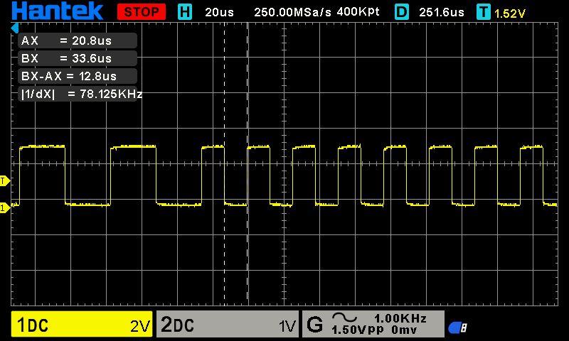
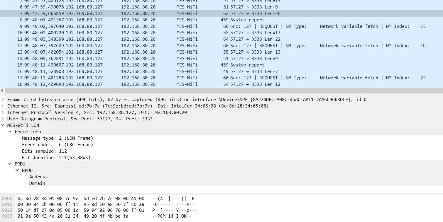
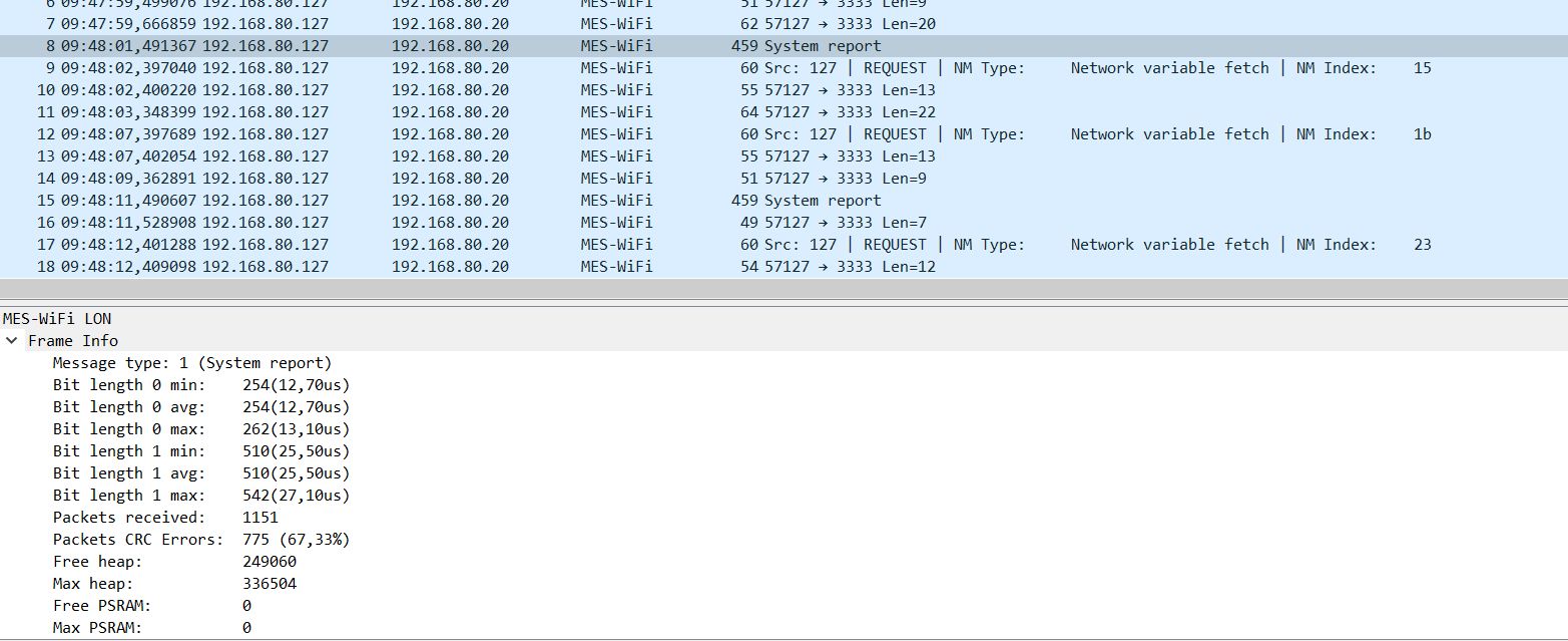
Hi all there,

First thanks for all your work this is awesome. I tried to use the MES
Wifi firmware on a BIOWIN2 but I have trouble parsing messages and I am
seeking some help.

I get CRC errors from messages coming from the bus. Message sent by the
esp are read back correctly on the rs485 loopback and there seems to be
an answer to every esp requests. Scope signal taken on esp rx pin looks
good so i don't really understand, it looks like a decoding problem.
I am using a lolin32 board with a rs485 module board, I already tried to
change hardware.
Any ideas ? Thanks
As a follow up I checked out the previous commit on
https://github.com/g3gg0/MESWiFi.git and now it is working fine. So
there might be a bug in this last commit.
Found out that it works for a value of bits_overlap of 1 or 2 but not
above. Last commit set it to 3.
You are right, the value 2 is a lot more stable. Thanks!
No idea why it made it into the repo.
I also updated the repo to be used with PlatformIO, not arduino.

It also now has
a) a web interface
b) SoftAP if no config was found (http://192.168.4.1/)
c) configurable MQTT server and wifi credentials
d) versioning (see web interface)
e) binary releases and update-via-http feature
(https://g3gg0.magiclantern.fm/Firmware/MES-WiFi/firmware.bin will be my
latest release, currently v1.3 - 1a0128a)


For building from source:

If you don't have WSL installed: edit platformio.ini and change

> build_flags = !bash -c "echo -Isrc -DDEBUG_ESP_HTTP_UPDATE
> -DDEBUG_ESP_PORT=Serial -DPIO_SRC_REVNUM=$(git rev-list --count HEAD)
> -DPIO_SRC_REV=$(git rev-parse --short HEAD)"

to

> build_flags = -Isrc -DDEBUG_ESP_HTTP_UPDATE -DDEBUG_ESP_PORT=Serial
> -DPIO_SRC_REVNUM=0 -DPIO_SRC_REV=none
Can it be build with arduino IDE 2.0 ? I am having problems with the
error
"error: 'PERIPH_RMT_MODULE' was not declared in this scope". and have
tried IDE 1.8.1. but still get the same error.


Best regards Claus
Claus L. schrieb:
> Can it be build with arduino IDE 2.0 ?

> I also updated the repo to be used with PlatformIO, not arduino.

probably not :)
I am working with PlatformIO only now for this project.
Did someone manage to send command ? Like changing heating mode,
ordering a water heater cycle, or temperature settings.

And is it the same protocol on the Ebus line ?
Angehängte Dateien:
-

mqtt.png
5,6 KB -

Screenshot_2022-09-29_192747.png
16 KB -

Screenshot_2022-09-29_193022.png
69 KB -

Screenshot_2022-09-29_201949.png
7,7 KB
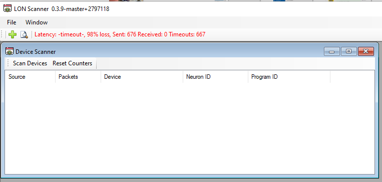
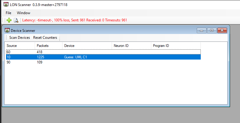
Dear all,

I´m deeply impressed by the work that has been done yet in this place!
Respect!!!

A Windhager BioWin Exclusive wants to be connected to my MQTT ecosystem.
I´ve compiled the MESWifi (GIT latest), and flashed it to an ESP32,
which connects via a RS485 adapter board to the LON bus.
Some data was available immediately, but unfortunately I can only see
some of the variables.

Tried to get a deeper understanding with LonScan, but somehow it seems
that there are connection issues.

ESP sends it´s udp data to broadcast (x.x.x.255:3333), and Lonscan sends
also to broadcast (x.x.x.255:3334). Unfortunately Lonscan tells me that
all packets get lost. (Timeouts constantly increasing)

Can someone help me to figure out what´s wrong with my setup?

Please forgive, if I have read something wrong... ;-)
Christian R. schrieb:
> Can someone help me to figure out what´s wrong with my setup?

Welcome.

Send the packets to the specific IP instead of the broadcast address.

Regards,
Georg
Angehängte Dateien:
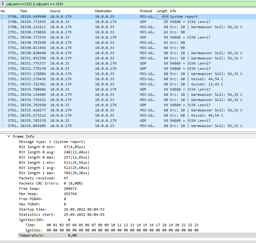
Georg H. schrieb:
> Send the packets to the specific IP instead of the broadcast address.

I´ve already tried to send the traffic directly between my pc and the
ESP32, but this didn´t work either.
(Think i read somewhere that it only works with broadcast for some
reason)

Here´s the result with direct traffic. To debug a little further, I
added a serial debug message to the function (lon_tx) which sends data
onto the LON bus to see if the ESP receives udp packets. I see the debug
message appear on the ESP when Lonscan sends its udp requests, and it
should be transmitted to the bus. (Didn´t check yet if the data is
really sent to the LON physically with an Osci)

Yet I´m unsure if it´s a problem on the ESP/LON side or a plain network
thing between the ESP and Lonscan. Is the lack of visible values caused
by not correctly set NV´s in my software because my heating differs from
yours, or should be more values visible anyway when the get polled
properly?
Christian R. schrieb:
> Yet I´m unsure if it´s a problem on the ESP/LON side or a plain network
> thing between the ESP and Lonscan. Is the lack of visible values caused
> by not correctly set NV´s in my software because my heating differs from
> yours, or should be more values visible anyway when the get polled
> properly?


Maybe the TX path isn't working and the LON network doesn't see the
messages of the ESP32.
Are you sure about the wiring being correct?
i.e. the enable pin and the tx pin to the transceiver
Georg H. schrieb:
> Are you sure about the wiring being correct?
> i.e. the enable pin and the tx pin to the transceiver

I´ll check it with an osci later, thanks so far!
Angehängte Dateien:
-

4032-3024-max.jpg
240 KB
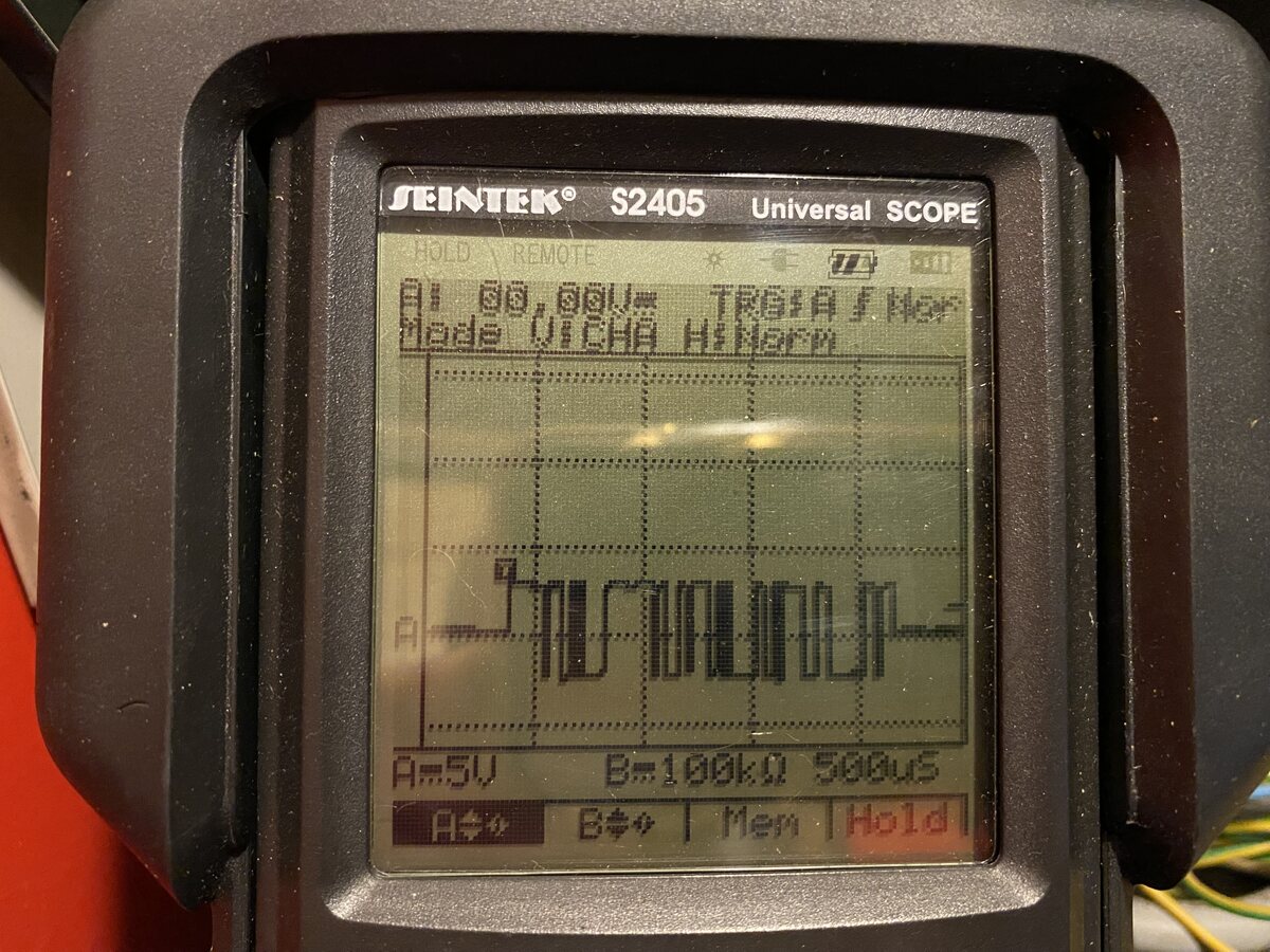
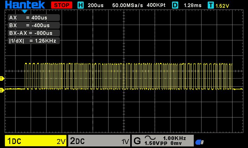
This is the LON bus when the heating is shut off. So it shows only the
data that is sent by the ESP. Doesn´t look too bad IMHO.
Is this A-to-B on the LON bus?
Are you using the latest git revision?
Georg H. schrieb:
> Is this A-to-B on the LON bus?
> Are you using the latest git revision?

Yes and yes. I downloaded the zip from git on 25.9. so it is the latest.
Picture is not very good, sorry for that. But you can clearly see the
differential voltage. I switched the heating also on and measured again
to see if the signals from my rs485 adapter are at the same voltage
level. (barely no difference)

What puzzles me is the fact that I see some of the values, which seem to
come cyclically and don´t need to be polled. Right?. That works ok, very
low CRC error rate (1-2%) which lets me believe that the connection is
right in this place.
But on the other hand it seems that the NV´s which are requested by
MESWifi never get answered by some node.
Even the requests from Lonscanner aren´t gonna answered from another
node.

So I share your opinion that TX path must somehow be not right.
But I see that it sends something which does not look that bad when
viewed on  the Oscilloscope....

One of these RS485 adapters is used:
https://www.amazon.de/WINGONEER-MAX485-RS485-RS-485-Entwicklungsboard/dp/B06XHHWLMW

It is supplied with 5V, RO pin is connected through a voltage divider to
clip input voltage at 3.3V to GPIO35. RE/DE are connected to GPIO 26. DI
is connected to GPIO25.
A is connected to LON+ and B to LON-

Did I miss anything?
Christian R. schrieb:
> Did I miss anything?

cough no...

fetch the latest version from git now and try again... :)
Thats weird... now it seems that Lonscanner can poll the device, I see
some data now...
But the last commit on the Git repo is 15days old...

Did I really managed it to work with an old/wrong version??
No, I just forgot to push the last change I made :D
This change was 2 weeks ago.
Georg H. schrieb:
> No, I just forgot to push the last change I made :D

A classic... happens to me 1-2 times per year @ work and always makes me
going nuts before someone asks: did you push it?? :D :D :D

Glad it´s working now and thank you for your effort.
I can work from here to customize the code to my heating system. Some of
the NV´s are differing against the hardcoded ones in LON.ino/MQTT.ino.
Would be great to have id implemented more modular and separated, so a
future code update doesn´t break customizations.

Your code is great work, and I think a lot of people could/will use it!!
:)
Great to hear that it works :)
If you have contributions, feel free to send pull requests.
Hello

Ok, so I have downloaded VSCode, installed PlatformIO and WSL, and
downloaded your MES-WiFi from Github, Georg.

I have opened it in VSCode/PlatformIO and can see the Project Tasks
"Default", "MES-WiFi" and "MES-WiFi_ota".

Compiling does not work with the "!bash" build flags, but it does work
with the "-Isrc" build flags.

Out of curiosity, what do I need to do to get it working with WSL and
the "!bash" build flags?

I am new to VSCode, PlatformIO and WSL.

Will continue with trying to getting this into an M5Stack Core2
connected to my Windhager Biowin.
Thomas N. schrieb:
> Compiling does not work with the "!bash" build flags, but it does work
> with the "-Isrc" build flags.
>
> Out of curiosity, what do I need to do to get it working with WSL and
> the "!bash" build flags?

this is for fetching the git version number via scripts.
you can set the defines manually to something you want - or - install
git.

regards
Wer noch Interesse an einer PCB hat, bitte melden.

Hier haben sich auch ein paar gemeldet:
https://github.com/g3gg0/MESWiFi/issues/1

Ich hoffe da kommen keine Doppelmeldungen :)
Hallo Georg, eine tolle Arbeit!

Ich habe gerade auch im Github eine, wenn es irgendwie geht, fertig
bestückte Platine angefragt. Leider kann ich mein Löten nur als Braten
bezeichnen.

Vielen Dank und Grüße

Holger
Hallo,

würde auch folgender Adapter funktionieren, dieser braucht aber keinen
TX enable pin d.h. den kann ich einfach weglassen oder? Verwendet den
MAX13487.

https://www.amazon.de/gp/product/B07B667STP/ref=ppx_yo_dt_b_search_asin_title?ie=UTF8&psc=1

Btw - kann man die serielle konsole oder zumindest die LON werte auch
ins WebIf packen, hätte es versucht bin aber kläglich gescheitert.

danke!
Angehängte Dateien:
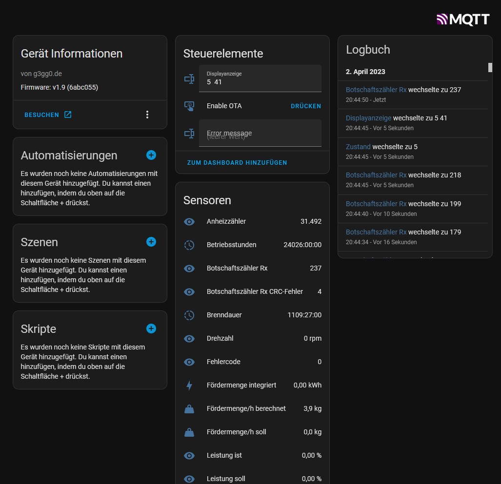
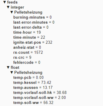
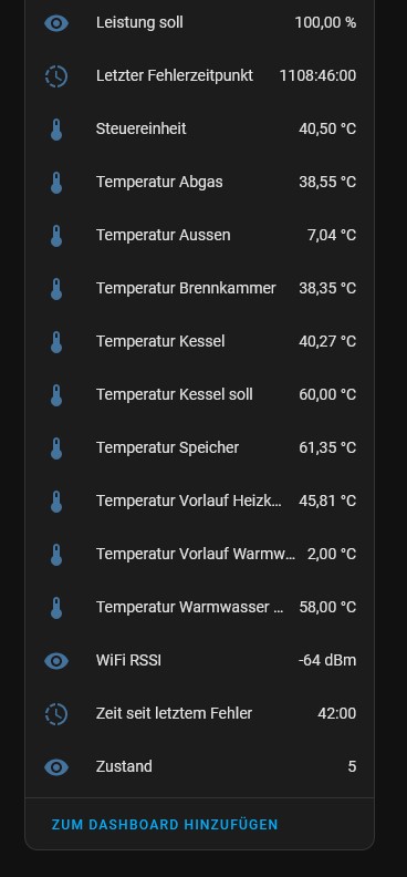
Kleines update von meiner Seite.

Ich hab mir mittlerweile einen Home Assistant eingerichtet und baue
langsam meine MQTT-Geräte so um, dass sie dem HA die config-messages
gleich mitschicken.

So hab ich das jetzt auch bei MES-WiFi gemacht.

Screenshots anbei.

Gruß,
Georg
Angehängte Dateien:
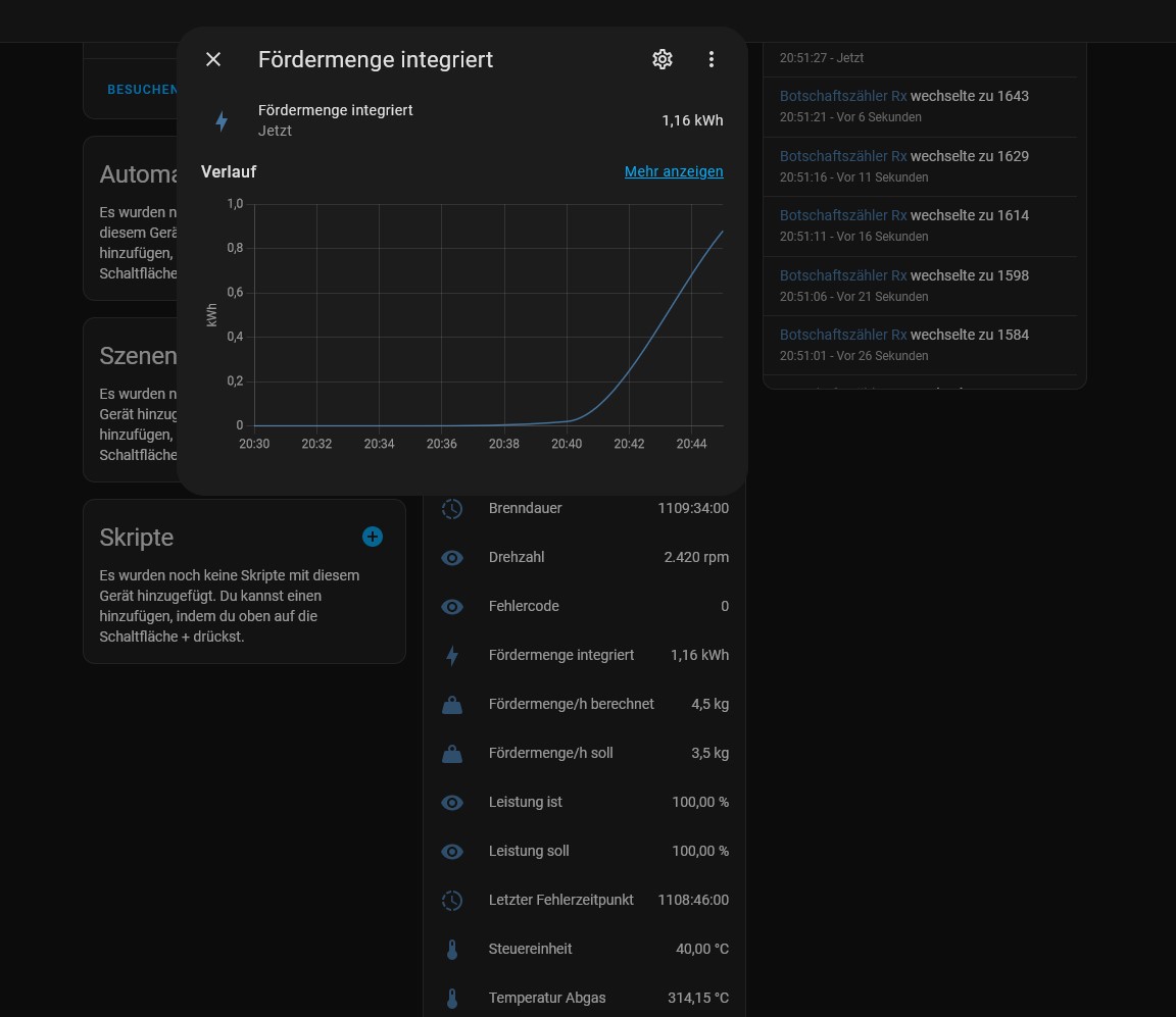
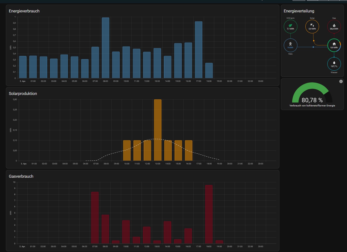
Hier läuft die Heizung grad an.

Dieser Wert ist geeignet, um die "Energiemenge", die verheizt wurde zu
tracken.
Ich berechne diese, indem ich die "Fördermenge [kg/h]" mit der
Energiemenge von Pellets 4.8 [kWh/kg] multipliziere und das jede paar
Sekunden integriere.

Für mich schaut es so aus, als würde des passen.

Am Ende kann man sich das dann auch im HA visualisieren lassen.
Hallo Georg wie hast du die ganze Programmierung auf den ESP32 geflasht
bzw. Finde ich diese?
Servus.

Die findest du hier:
  https://github.com/g3gg0/MESWiFi
Ich nutze Visual Studio Code mit dem PlatformIO addon.

Gruß,
Georg
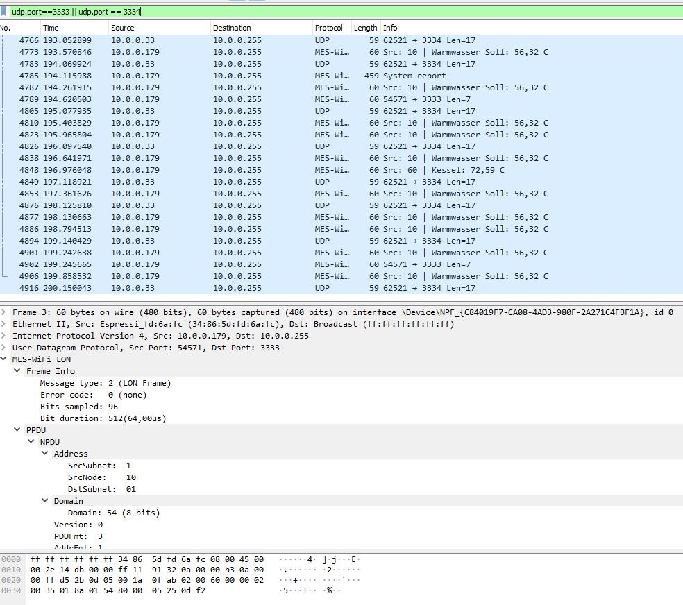
Hallo,

nachdem ich Georg ordentlich per Nachricht genervt habe, bin ich bei
meiner Suche auf diesen Thread gestoßen :-)

Leider komme ich nicht weiter:
Ich habe einen ESP32 mit Max485 Transceiver erfolgreich in Betrieb
nehmen können.
Nun unterscheidet sich meine Paradigma MES wohl in ein paar Details.
Ich konnte das Wireshark LUA erweitern und so einige Daten verfügbar
machen, es fehlen aber noch einige Daten, die auch nicht als UNKNOWN in
Wireshark auftauchen.

Es fällt zugegeben schwer, Euren ganzen Ausführungen zu folgen, daher
die Bitte um Ideen, wie ich mein Ziel doch noch erreichen kann.

Es sind folgende Punkte für mich noch ungelöst:
1.) Wieso sehe ich nicht alle Daten, zB.: Temperatur Solarausgang sehe
ich, Eingang nicht, Drehzahl Pumpe sehe ich nicht, Brennerstatus der
Gastherme kann ich nicht zuordnen, oder sehe ich nicht. Muss man auf den
LON noch einen Request senden, um alles zu sehen?
2.) Kann man die Uhrzeit in den MES Geräten per ESP32 setzen? Ist das
richtig? Das wäre ja unglaublich toll, nach Stromausfall ist bei mir
immer alles auf 1997...

Ich habe auch LON Scan probiert, da sehe ich aber nichts, irgendwann
stürzt es einfach ab.

Danke vorab,
Ron

PS: Sorry nochmal Georg, ich hatte den Thread vorher nicht gefunden.
Angehängte Dateien:
-

lon.png
130 KB
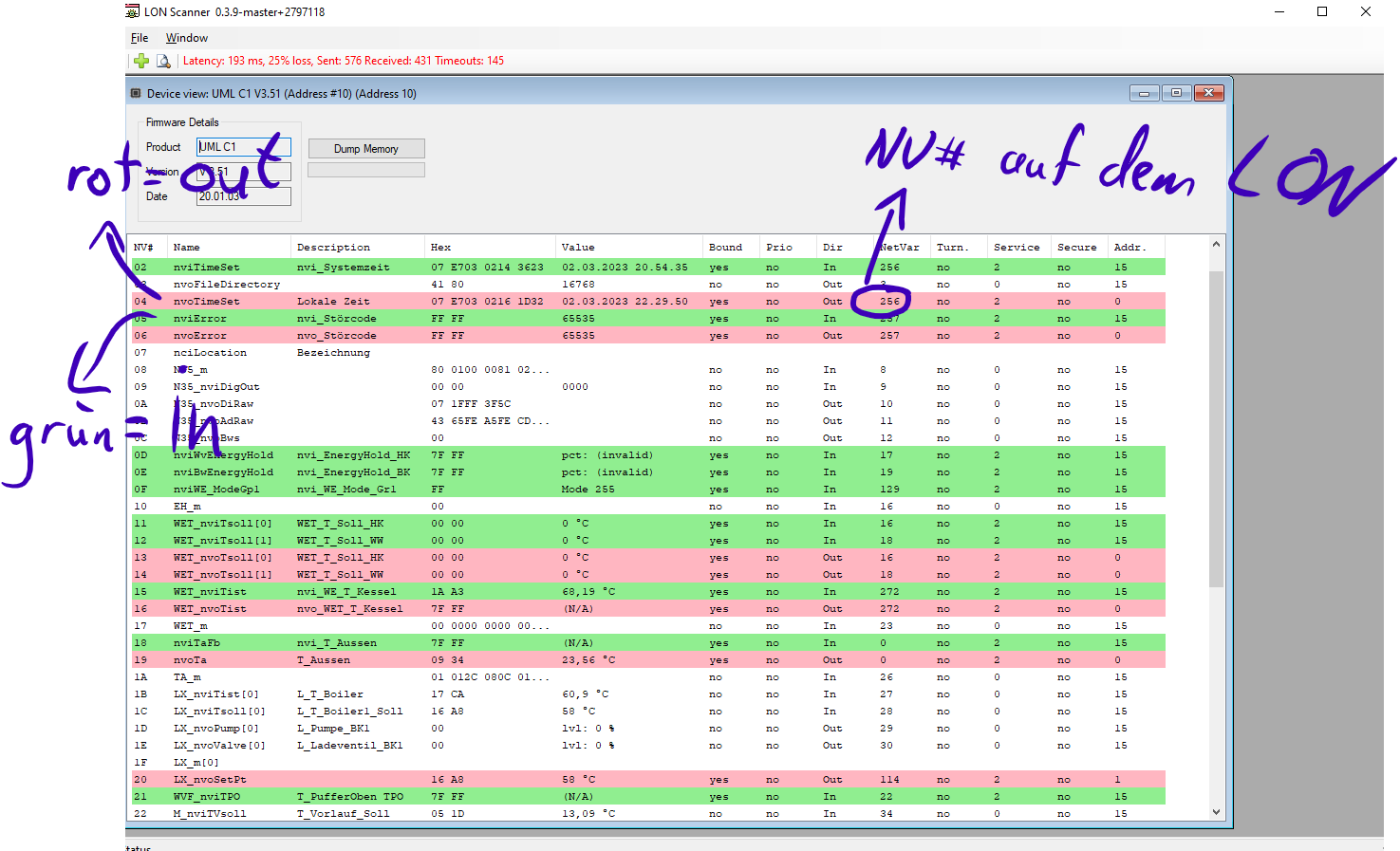
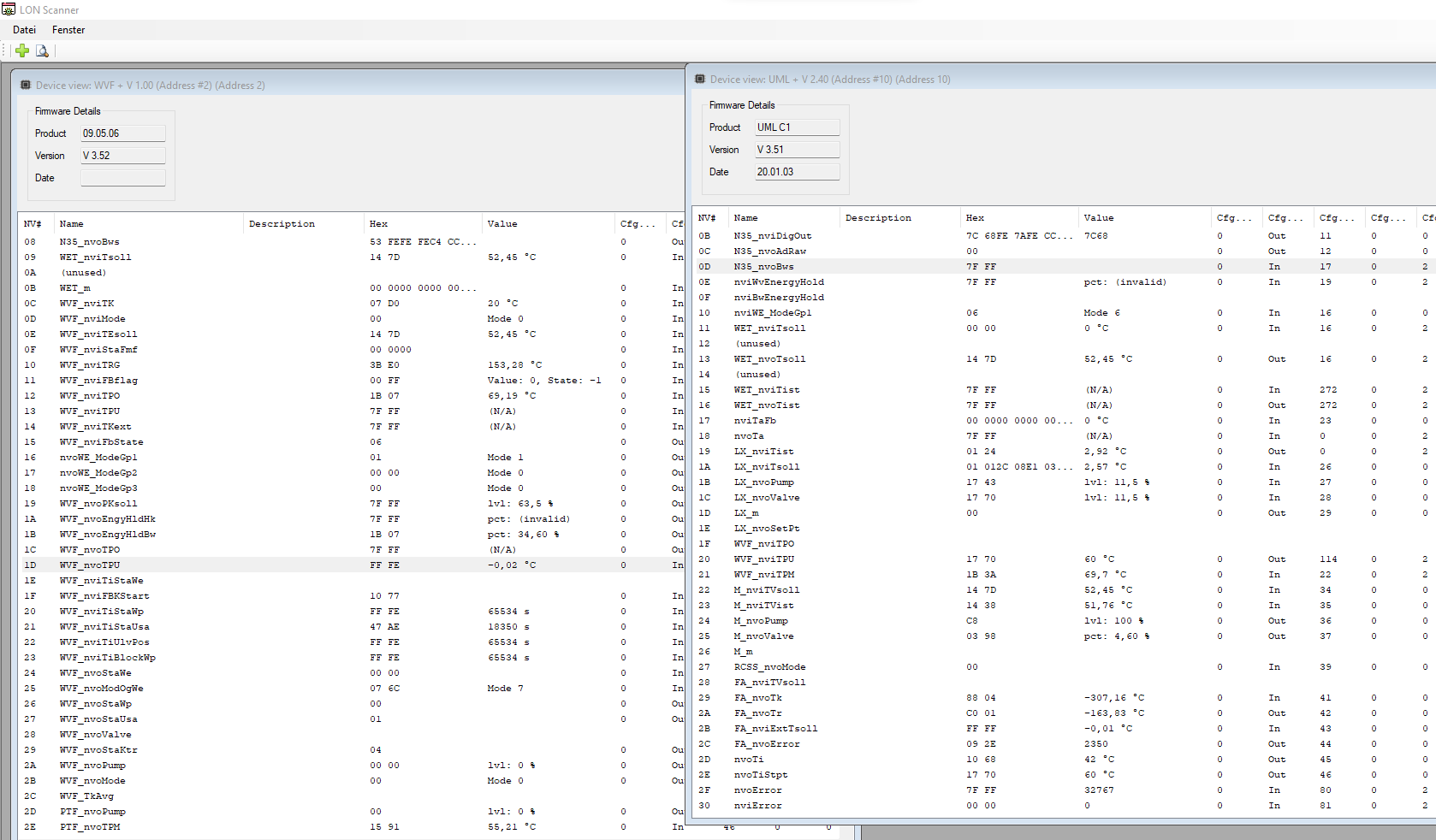
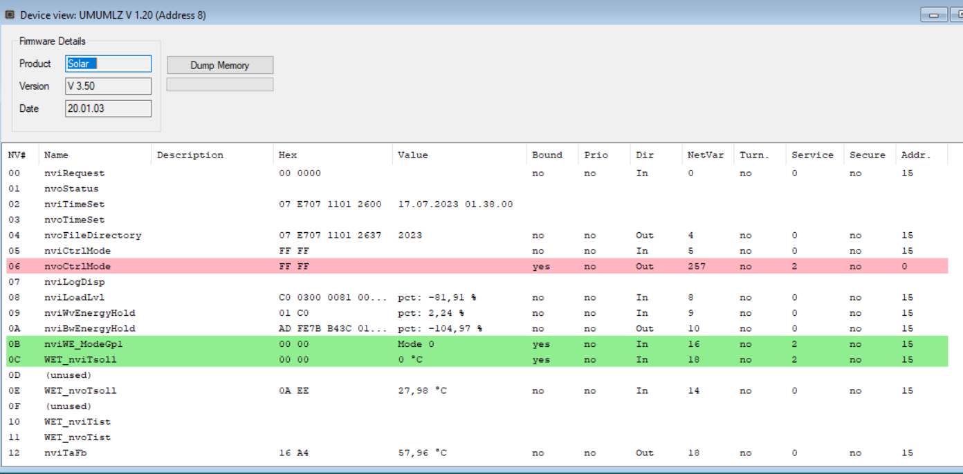
Alles gut. Wenn ich keine Zeit habe, dauern Antworten oft etwas :D
Und da ich viele Hobbies hab, gerät da auch oft was in Vergessenheit.
Alles etwas lang her, daher der Versuch, das zu erklären.

Also ein paar Infos werden von der Heizung zyklisch als Network Variable
(NV) rausgesendet.
Die Infos legen quasi als broadcast auf dem LON-Bus.

Andere Variablen lese ich gezielt aus. Ich glaub die heissen auch NV,
werden aber nicht aktiv gesendet.
Dazu frage ich per LON-Protokoll gezielt die NVs an.

Mit meinem C#-Tool LonScan kann man das für die jeweiligen Module sehen,
was sie auf dem Bus als Broadcast senden.
Aber davor müssen die Module erst im .cfg konfiguriert werden.
Ich hab dazu alle Windhager .xif eingelesen und entsprechend im .cfg vom
LonScan aufgelistet.

Du kannst ja erst mal mit dem "Suchen" Button neben dem grünen Plus das
Netz durchsuchen. Mal kucken, was da so gefunden wird.
Wenn dann rechtsklick "Add as xxxx" machst, kommt ein Dialogfeld in dem
Firmware details stehen.
Am besten mal screenshots davon machen.,
Ron S. schrieb:

> 2.) Kann man die Uhrzeit in den MES Geräten per ESP32 setzen? Ist das
> richtig? Das wäre ja unglaublich toll, nach Stromausfall ist bei mir
> immer alles auf 1997...

Ja, kann man: "File -> Set system time"
Aber z.B. UML C1 haben ihre eigene Zeit.
Ich hab noch nicht rausgefunden, wie ich bei denen in die config komme
:(

Wenn hier einer nen Tip hat, gern her damit :)

> Ich habe auch LON Scan probiert, da sehe ich aber nichts, irgendwann
> stürzt es einfach ab.

Ich hab ein paar Änderungen gemacht. Crasht das tool noch?
Und wenn ja, screenshots bitte.
https://github.com/g3gg0/LonScan/releases/tag/v0.4.0
Hallo Georg,
vielen, vielen Dank.
Das bestätigt aber im gewissen Rahmen meine Annahme, dass mir die
Requests fehlen.
Gibt es irgendeine Chance, den Aufbau dieser Requests zu erlernen?
Es erinnert mich sehr an CAN-Bus, aber da hatte ich eine Doku und konnte
die Abfragen als CAN Nachricht senden.
Hier habe ich es noch nicht verstanden.
Ich glaube auch, dass ich die Geräte IDs einfach noch nicht alle kenne.
Die alte MES von Paradigma bei mir ist wahrscheinlich noch älter als
Eure Pellet Systeme, scheint aber identisch zu funktionieren.
Ich glaube, mir fehlt einfach so eine Initial-Zündung, vielleicht ein
Beispiel, keine Ahnung.
Das Tool teste ich gerne, es ist aber möglich, dass es bei mir nicht
funktioniert, weil ich ein UniFi Netzwerk einsetze, für Wireshark musste
ich auch direkt über die Konsole tracen.
Was praktisch ist: ich habe vor einiger Zeit eine Platine gebaut, die
als Ersatznetzteil dient, davon konnte ich eine unbestückte Platine
verwenden, um an die 12V zu kommen, damit ist es per Bauer Step-Down nun
einfach, das vorhandene Leergehäuse zu verwenden :-)
Also wenn es noch ein Beispiel, einen Hinweis zu den Requests oder
ähnliches gibt, immer her damit!
Noch einmal: ich bin wirklich dankbar, so komme ich vielleicht noch ans
Ziel.
Gruß
Ron
Komisch, bei iPhone Nutzung fehlt die Formatierung des Textes, sorry.
hab noch einen crash reporter eingebaut, der das vllt etwas einfacher
macht
https://github.com/g3gg0/LonScan/releases/tag/v0.4.1
Angehängte Dateien:
-

lon_pkt.png
24 KB
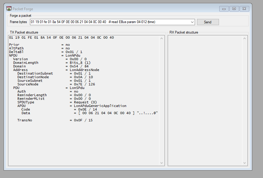
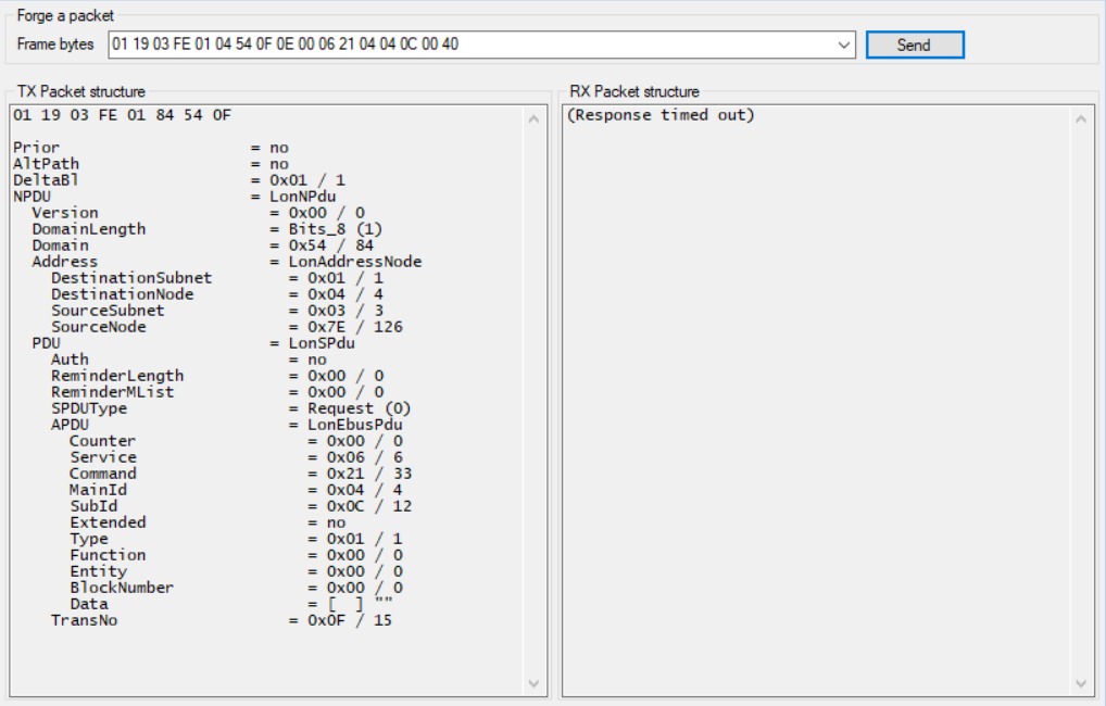
> Gibt es irgendeine Chance, den Aufbau dieser Requests zu erlernen?
> Es erinnert mich sehr an CAN-Bus, aber da hatte ich eine Doku und konnte
> die Abfragen als CAN Nachricht senden.

Ja, es gibt eine spec dazu - google mal nach "LonTalk Protocol
Specification"
Macht keinen Spass zu Lesen, aber es gibt sie...

Ich hab auch einen "PacketForge" gebastelt, mit dem du Pakete selber
bauen kannst: "File -> PacketForge"
Der dekodiert dir auch die Pakete und du kannst die senden und die
Antwort anschauen.

Warum das mit deinem Netzwerk nicht geht, müsstest du mir noch genauer
erklären.
Ich denke, muss aber nochmal schauen, dass bestimmte Funktionen bei mir
geblockt werden.
Wireshark funktionierte auch nicht über das Wifi, sondern nur über
tcpdump.
Daher meine Annahme.

PacketForge könnte ein guter Ansatz sein, ich frage mich nur, wohin ich
was senden muss, aber vielleicht ist das ja Teil der erwähnten Doku.

Eine Firmware zerlegen wird es bei mir wohl nicht geben. Ich kenne
keine, aber auch viele Geräte aus Deiner Config sind mir unbekannt, UML
etc kenne ich, aber das war es fast schon.

Danke :-)
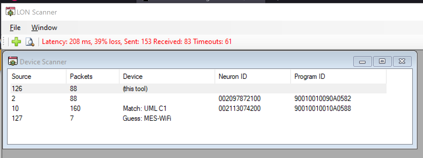
Wenn du einen Scan machst, solltest du alle Geräte auf dem Bus finden.
Angehängte Dateien:
-

IMG_6802.png
15 KB
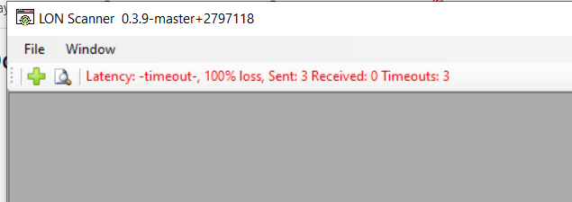
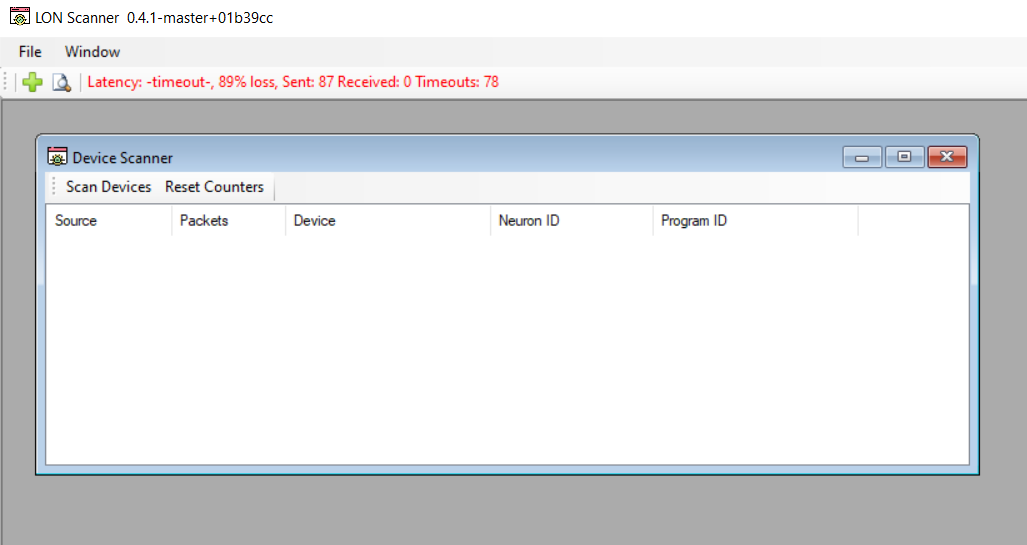
So wie hier im Anhang sieht es immer aus, 100% loss.

Keine Ahnung, wie gesagt, vielleicht verhindert das Netzwerk etwas an
der Stelle, Config ist länger her :-)
Du hst die IP-Adresse des ESP32 im .cfg angegeben?
Die IP ist auch von deinem Rechner auch erreichbar?
cmd.exe -> ping <IP>
Angehängte Dateien:
-

2023-07-17_00h28_48.png
34 KB -

2023-07-17_00h32_40.png
13 KB -

2023-07-17_00h33_50.png
9 KB -

2023-07-17_00h36_00.png
65 KB -

2023-07-17_00h36_52.png
8 KB -

2023-07-17_00h37_35.png
78 KB
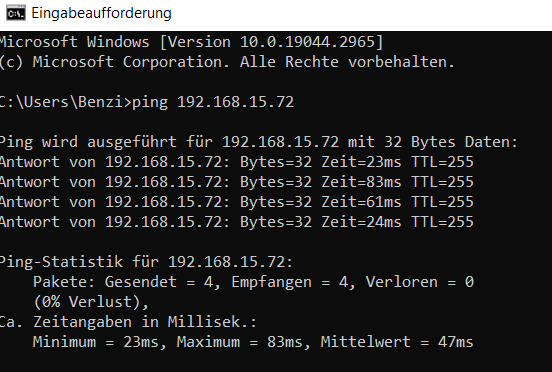
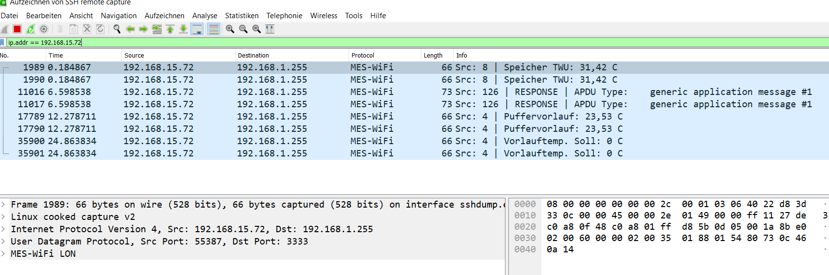
Ich habe die IP eingegeben, aber leider passt was nicht.
Ping funktioniert einwandfrei...
Wie gesagt, Wireshark auch nicht so einfach.
Über ssh dann schon, siehe Bilder...
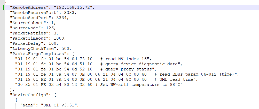
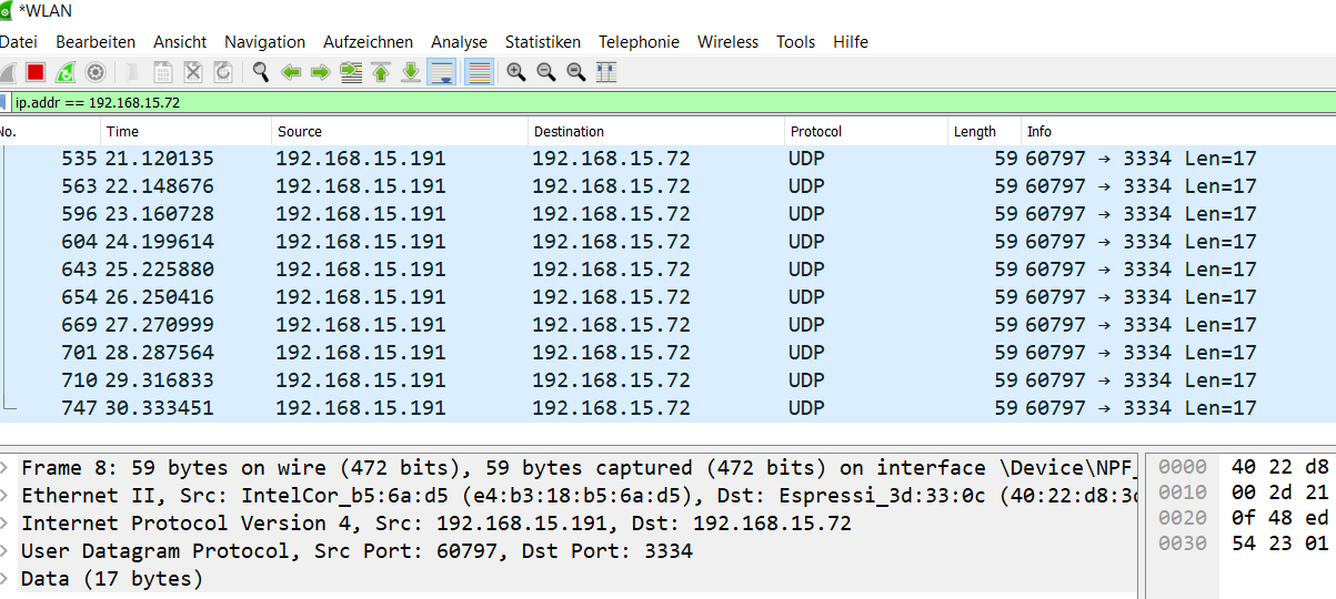
Könntest du die firmware des ESP32 so konfigurieren, dass die
broadcast-address korrekt ist?
LON.ino
von: const char *udpAddress = "192.168.1.255";
auf: const char *udpAddress = "192.168.15.255";
Ich denke schon, dafür muss ich nur neu compilieren, oder?
Mittlerweile läuft VS Code mit PlatformIO gut.
Ich habe es nur noch nie vom PC hochgeladen, bis jetzt nur Mac.
Ist auf Git die aktuellste Version?
Meine erste Version hat sich mit "V1." gemeldet und nach einem Update
kam dann "V1.6".
Ron S. schrieb:
> Ich denke schon, dafür muss ich nur neu compilieren, oder?

korrekt.
einfach source abändern und flashen
Angehängte Dateien:
-

2023-07-17_01h27_19.png
30 KB
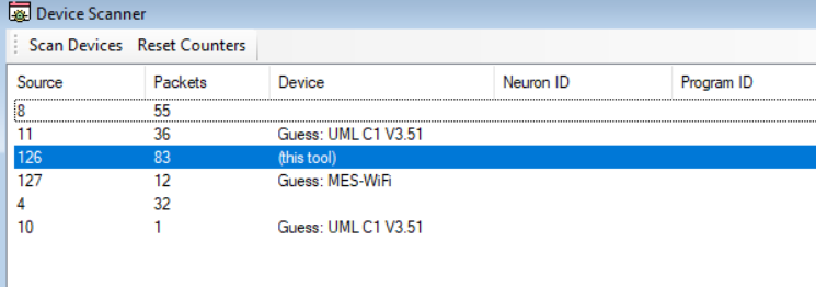
Jetzt geht Wireshark und Dein Tool auch ;-)

Nun, da bin ich ein Stück weiter...

Was mache ich jetzt damit?
Angehängte Dateien:
-

2023-07-17_01h39_45.png
130 KB -

2023-07-17_01h40_30.png
120 KB
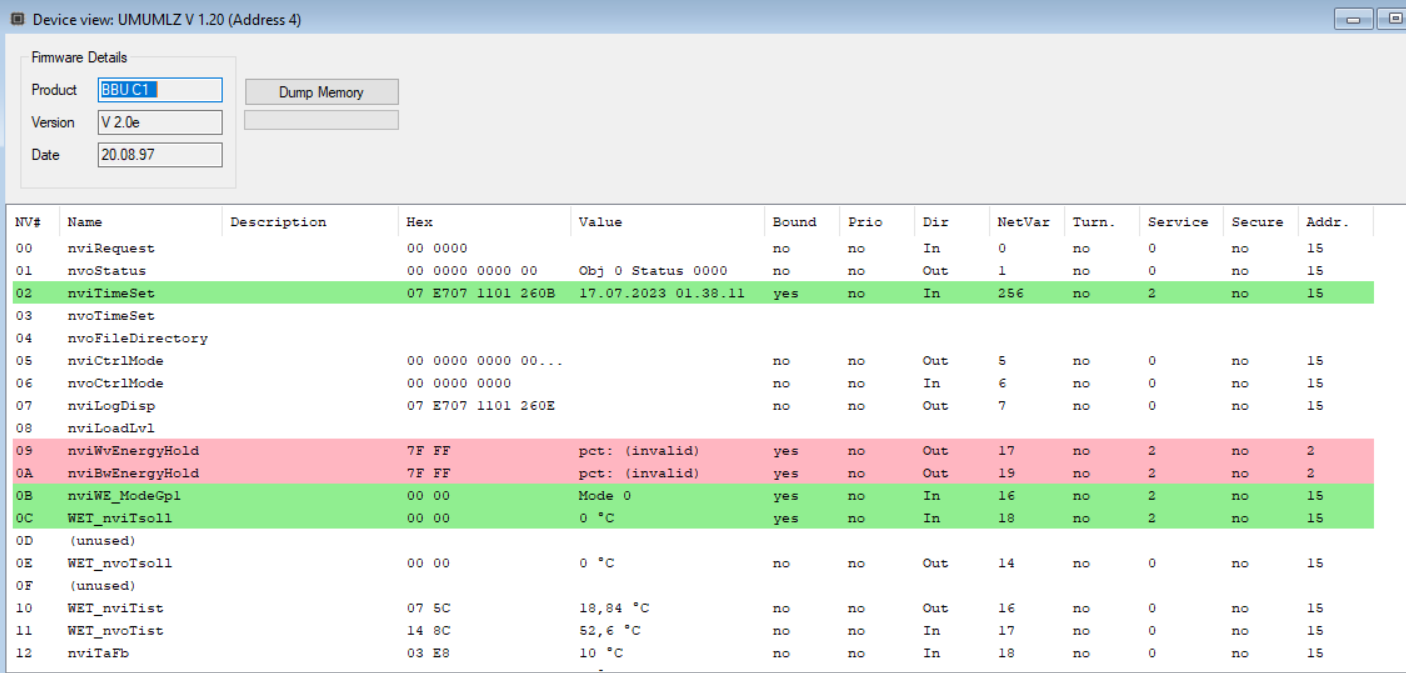
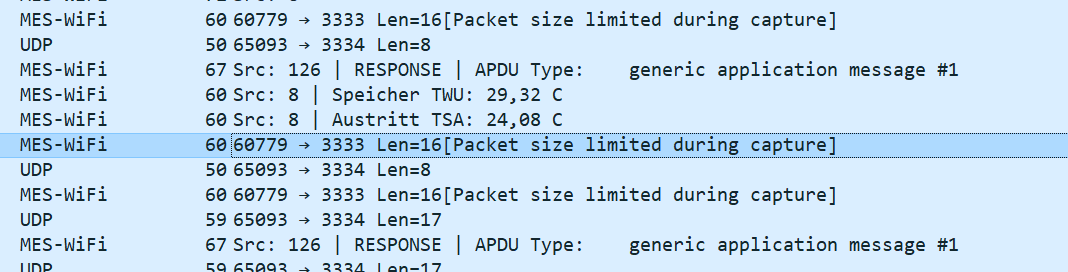
Ich finde, dass sieht brauchbar aus, die Firmware ist steinalt :-)

Aber wie bekomme ich diese Daten am Ende vom ESP32 in meinen MQTT
Stream?
...dazu musst du hässlich geschriebenen source code selbst ändern :)

Ausserdem würde ich erst mal prüfen, ob die Konfiguration überhaupt
korrekt ist.
Kann gut sein, dass meine Daten hier unvollständig sind.
Ok, verstanden, da die Daten ja in Deinen Abfragen sind, sollte man das
anpassen können und dann in den Abfrage Loop des ESP32 integrieren.

Vielen Dank, wieder ein Stück weiter.

Hoffentlich kommt der Knoten im Kopf nicht wieder und ich komme dahin,
wo ich hin möchte, einfach nur einen Alarm mitbekommen :-)
> Hoffentlich kommt der Knoten im Kopf nicht wieder und ich komme dahin,
> wo ich hin möchte, einfach nur einen Alarm mitbekommen :-)

Wird sicher beides passieren :D
Guten Morgen,
hast Du noch einen Tipp, wie man die Remote Update Funktion nutzt?
Dann muss ich nicht immer zum ESP32 rennen, sondern könnte schneller
meine Ideen testen.
Gruß
Ron
In PlatformIO kannst du unten in der Statuszeile das aktuelle Projekt
auswählen und dann kann man per remote update die software updaten.

In PlatformIO gibts eine section für die Projektvariante
"[env:MES-WiFi_ota]" in der platformio.ini in der die IP-Adresse des µC
hinterlegt ist.
Hier die IP deines ESP32 eintragen und dann sollte das "Upload" diese
updaten.

Ich glaube ich hatte die firmware so konfiguriert, dass das remote
update nur eine gewisse Zeit aktiv bleibt.
Per Home Assistant bzw MQTT kann man das wieder aktivieren.
Alternativ müsste auch http://<ip>/ota funktionieren.
Super,
gilt das auch für das Wifi?
Kann man die Parameter mit übergeben, damit man direkt wieder online ist
mit dem ESP32?
Was meinst du mit wifi?
Wenn einmal konfiguriert, werden die setings im SPIFFS gespeichert und
bleiben über Firmware updates hinweg bestehen.
Ok, ich teste und werde berichten :-)

Ich dachte, wenn man ein Update macht, muss man immer alles von vorne
konfigurieren. So wie beim USB Upload halt.
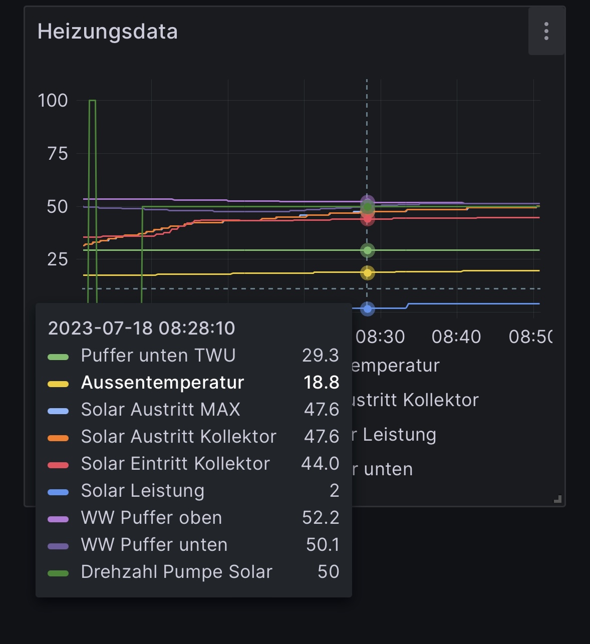
Kurzer Zwischenbericht:
Ich bin wahnsinnig weit gekommen.
Mittlerweile schreibe ich diverse Daten in die InfluxDB und zeige sie
mit Grafana an.

@Georg: kannst Du mir verraten, woher die Daten für die einzelnen Geräte
stammen? Es scheint mir so, dass meine Geräte andere Werte haben und
deswegen die Anzeige in Deinem Tool nicht stimmt. Wie kann ich das
berichtigen?

Bei Dir gibt es halt keine UML C1, BBU C1, Solar...

Danke,
Ron
Georg H. schrieb:
> Aber davor müssen die Module erst im .cfg konfiguriert werden.
> Ich hab dazu alle Windhager .xif eingelesen und entsprechend im .cfg vom
> LonScan aufgelistet.

die .xif hab ich aus dem service tool von windhager genommen.
Angehängte Dateien:
-

IMG_6816.jpeg
210 KB
Noch mal:
Vielen, vielen Dank für die Hilfe, ohne wäre ich jetzt nicht so weit.

Ich arbeite weiter an den Auswertungen und den Daten, eine XIF gibt es
von Paradigma eher nicht für meine Module.

Mal sehen, welche Werte ich noch finde.

Habe noch nichts für Brenner, Solarfurchfluss etc…, aber vielleicht wird
das noch :-)

Ich dokumentiere fleißig, welcher Wert was für Paradigma bedeutet,
vielleicht hilft das später auch noch mal…
Magst du im .cfg einen eigenen Eintrag anlegen und deine Erkenntnisse
dort einpflegen?
Kann ich machen, werden dann aber 3 - 4 Einträge, für jedes Device
einen.

Danach strukturiere ich auch gerade meine Doku.

Welches Gerät, welche ID, welches Signal, welcher Wert etc.
Ich bin weiter fleissig dabei, meine Doku und die CFG zu erweitern.

Noch scheitere ich an der Uhrzeit und dem Datum, aber vielleicht mache
ich auch was falsch?

Hast Du noch einen Tipp?
Es geht bei mir ja quasi nur um 2x UML, mehr Datum gibt es bei mir
nicht...
Georg H. schrieb:
> Ich habe die Zeit der PMX und der beiden UML gesetzt indem ich die
> network variable 0x100 entsprechend gesetzt hab.
> Die jeweiligen Geräte haben jetzt auch (laut ihrer NV) auch die Zeit
> übernommen. (yay!)

Was genau war dann damit gemeint?
Auslesen kann ich Datum und Zeit ja auch…
Alle Module haben eine Zeit-NV - aber das Bedieninterface des UML hat
wohl eine eigene Uhr.
Angehängte Dateien:
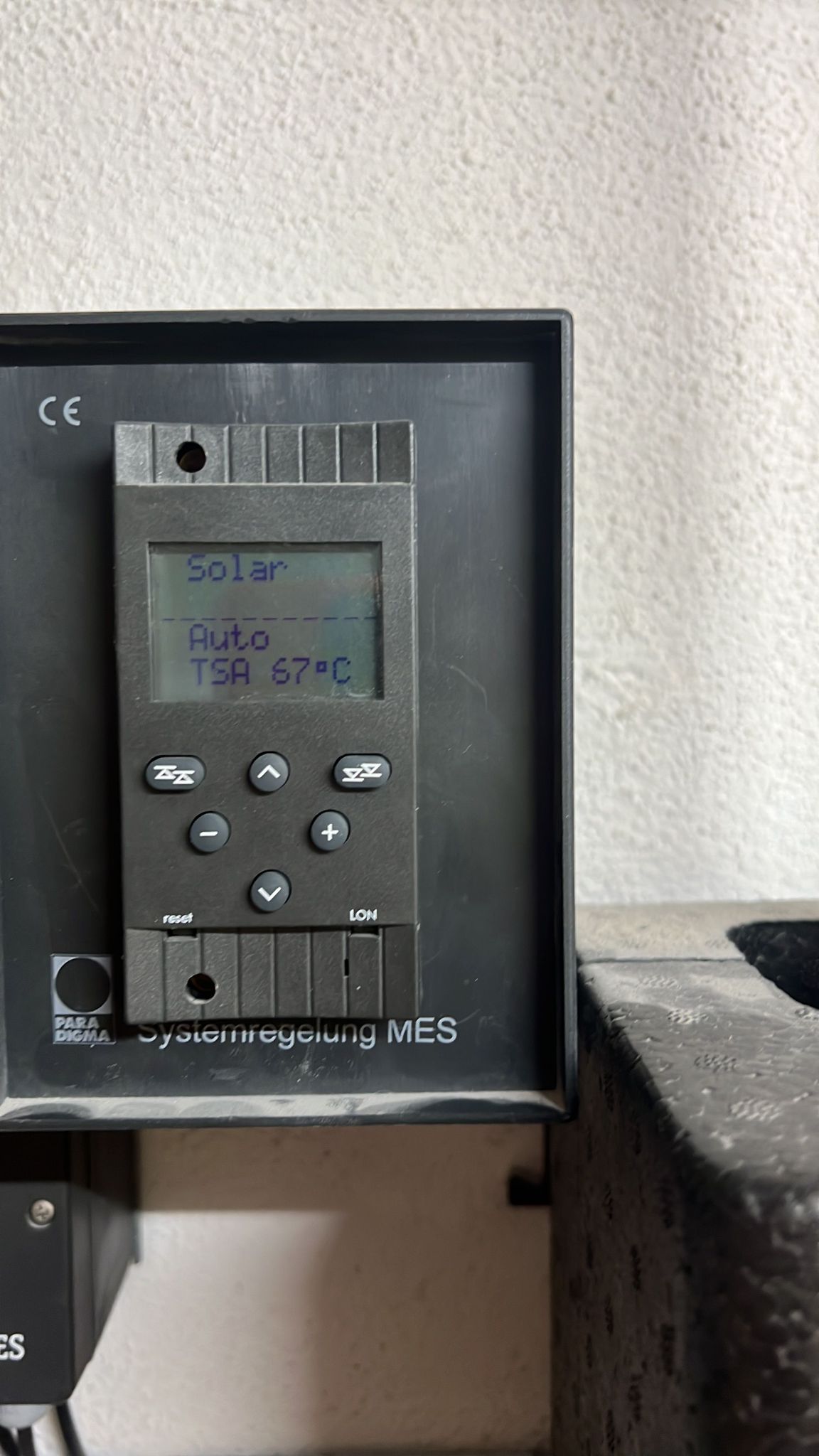
Ich habe nur die Geräte selber, kein Bedienteil.
Oder verstehe ich Dich nicht?
Siehe Anhang, Beispiel, dort soll die Zeit gesetzt werden.
Ich hab eine UML C1 mit dem Bedienteil rechts.

So eine:
https://img.kleinanzeigen.de/api/v1/prod-ads/images/de/de57a277-1310-49de-91f8-3c8a9729fef5?rule=$_57.JPG
(Der Link wird sicher nicht lang verfügbar sein)

Da ist es jedenfalls so, dass das Bedienteil die Uhrzeit des Moduls
ignoriert. Wie man diese programmieren kann, weiss ich noch nicht.
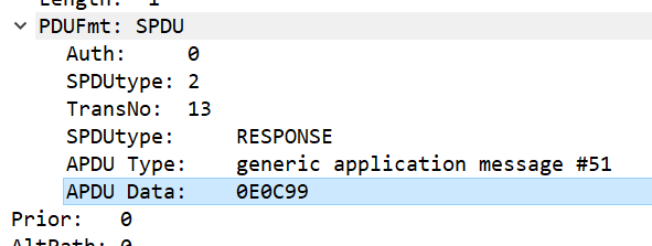
Hallo Ron,

Windhager verwendet zum "steuern" der Module sogenante "User Application
Message codes", nicht NV Variablen.

Auslesen kann man die zB. mit (Hex Werte am LON Bus):
1 | 0E 00 06 21 = READ_STANDARD_VARIABLE |
2 | |
3 | senden: 0E 00 06 21 04 02 C6 00 40 |
4 | Antwort: 0E 00 06 21 0A 46 01 04 28 E8 FD 00 00 05 AA -> (Datum,16.12.2077,1.1.1900,2.3.2019) |
5 | |
6 | senden: 0E 00 06 21 04 02 C8 00 40 |
7 | Antwort: 0E 00 06 21 0A 48 01 04 2A 9F 05 00 00 96 03 -> uml (zeit,23:59,0,15:18) |
8 | |
9 | senden: 0E 00 06 21 04 02 C9 00 40 |
10 | Antwort: 0E 00 06 21 0A 49 81 00 00 00 00 00 00 05 00 -> Wo-TAG (0=Mo, 5=Sa, 6=So) |
Setzen kann man Datum und Zeit zB so:
1 | 0E 00 06 23 = WRITE_PARAMETER |
2 | |
3 | senden: 0E 00 06 23 06 02 C6 00 40 13 AA -> set uml date (0xAA13 = 43539 Tage seit 1.1.1900 -> 16.3.2019) |
4 | Antwort: ACK |
5 | |
6 | senden: 0E 00 06 23 06 02 C8 00 40 95 03 -> set uml time (0x395 = 915 min seit 00:00 -> 15:17) |
7 | Antwort: ACK |
Wie du das senden kannst, kann dir sicher Georg sagen.
Und ob das bei allen UML funktionier, kann ich auch nicht sagen.
Bei meinem UML+ V2.0 funktioniert es so.

lg. Peter
Hallo Peter,
vielen Dank, in diese Richtung wollte ich, diese Basis hat mir gefehlt.
Vielleicht hatte ich mich auch nur falsch ausgedrückt.
Es stimmt, ich muss noch heraus finden, wie ich das auf den Bus bringe.
Leider ist es wirklich schwierig, dieses Projekt umzusetzen.
Allerdings macht es auch großen Spaß und ich würde mich freuen, wenn
mein kleiner Anteil noch mal einem Paradigma User bei der Fehlersuche
hilft.
Ohne die Hilfe hier wäre das sowieso alles nicht möglich.
Gruß
Ron
Könnte man so auch die Betriebsart setzen?
Also von Absenken auf Auto oder ähnlich?
Dann könnte man über den ESP32 nach Stromausfall wieder komplett auf
Normalbetrieb schalten, inkl aktuellem Datum/Zeit Faktor.
Angehängte Dateien:
-

UML.png
15 KB
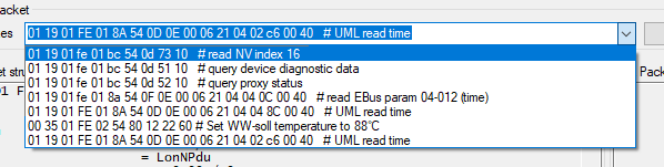
Super! Ich danke dir vielmals.

Habs noch nicht überprüft, aber werd mich heut Abend dran machen.
Ich hab vor geraumer Zeit schon mit den Nachrichten gespielt, wusste
aber keine Addressen und hab auch nie eine Antwort bekommen.

Im PacketForge sieht man schon die ein oder andere vorbereitete
Nachricht.
Wie gesagt, bei der "UML read time" kam aber nie eine Antwort.

Wo hast du die Adressen her?
Ich konnte nicht so lange warten, auch wenn meine Frau, die gerade den
Garten aufräumt mich dafür hassen wird :)

Ich bekomme bei keiner 0E (LonAPduGenericApplication) mit
READ_STANDARD_VARIABLE Nachricht eine Antwort.
Ah, ich erinnere mich. Das ist der EBus.
Aber irgendwie krieg ich beim UML C1 keine Antwort.
Hat die überhaupt einen EBus?

Aus meinen Notizen, als ich vor nem Jahr die Software etwas reverse
engineered hab:

APDU 0x0E -> EBUS command

Service 0x06 Command 0x21 "ReadEbusVariable"

  TT SS CC LL (ML MH SL SH)
  TT = transaction sequence number, incrementing
  SS = service (0x06)
  CC = command (0x21)
  LL = payload length (0x04)
  ML =  MainLow -> Main ID
  MH = MainHigh -> (extended ? 0x80 : 0x00) | SubID
  SL/SH = (type<<14) | (function<<9) | (entity<<4) | blockNumber

Service 0x06 Command 0x22 "ReadEbusVariableValue"
  see 0x21

Service 0x06 Command 0x23 "WriteEbusVariable"
   see 0x21, just LL and number of payload bytes incremented by the
variable width
Angehängte Dateien:
-

UML_EBUS.png
23 KB
Ich hab mir die OperationalData.xml für die "UML +" angekuckt.
Dort sieht man schön die EBus IDs

https://github.com/g3gg0/LonScan/releases/tag/v0.4.2
Hab mal PacketForge etwas erweitert, so dass man die EBus IDs sehen
kann.
Hallo Georg,

wenn ich bei mir über das Bedienfeld (InfoWin) Datum/Zeit ändere, werden
genau die Pakete am LON gesendet, die ich oben gezeigt habe.
Aber ich habe ein UML+. Ob das beim UML C1 auch so geht?

Wie kannst du Datum/Zeit ändern, an der Anlage? Und was sieht man da am
LON Bus?

Über NV Variablen ist es mir auch nie gelungen, Datum/Zeit zu stellen.
Nur zu lesen.
Angehängte Dateien:
-

LON_Bedienmodul.png
72 KB
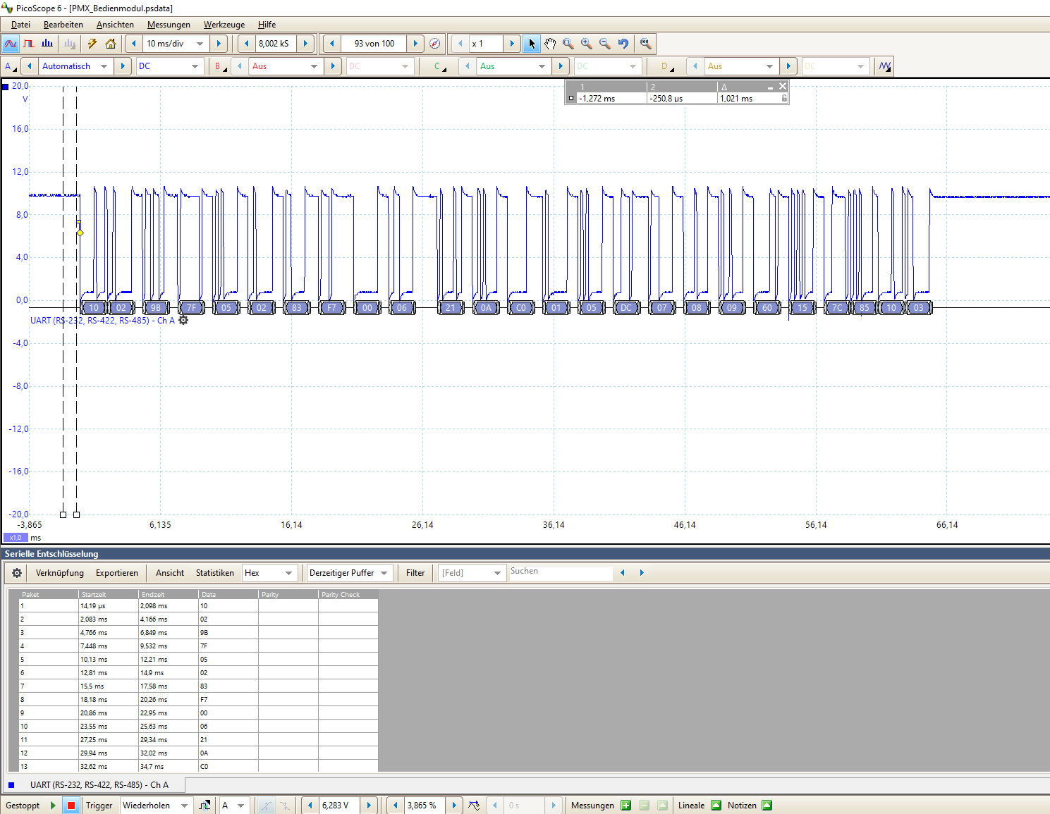
Das hab ich nicht angeschaut.

Bei mir sind die Bedienteile mit einem extra bus zu ihren jeweiligen UML
verbunden.
Ist kein LON, sondern irgendein serial.
UART, 4.8k, 9.7V, siehe screenshot.

Wenn ich an einem Bedienteil die Zeit einstelle, hat das keine
Auswirkungen auf das andere oder gar die NV des UML.
Daher glaub ich nicht, dass da irgendwas raus geht.
Angehängte Dateien:
-

IMG_6848.png
2,3 MB -

IMG_6845.jpeg
410 KB
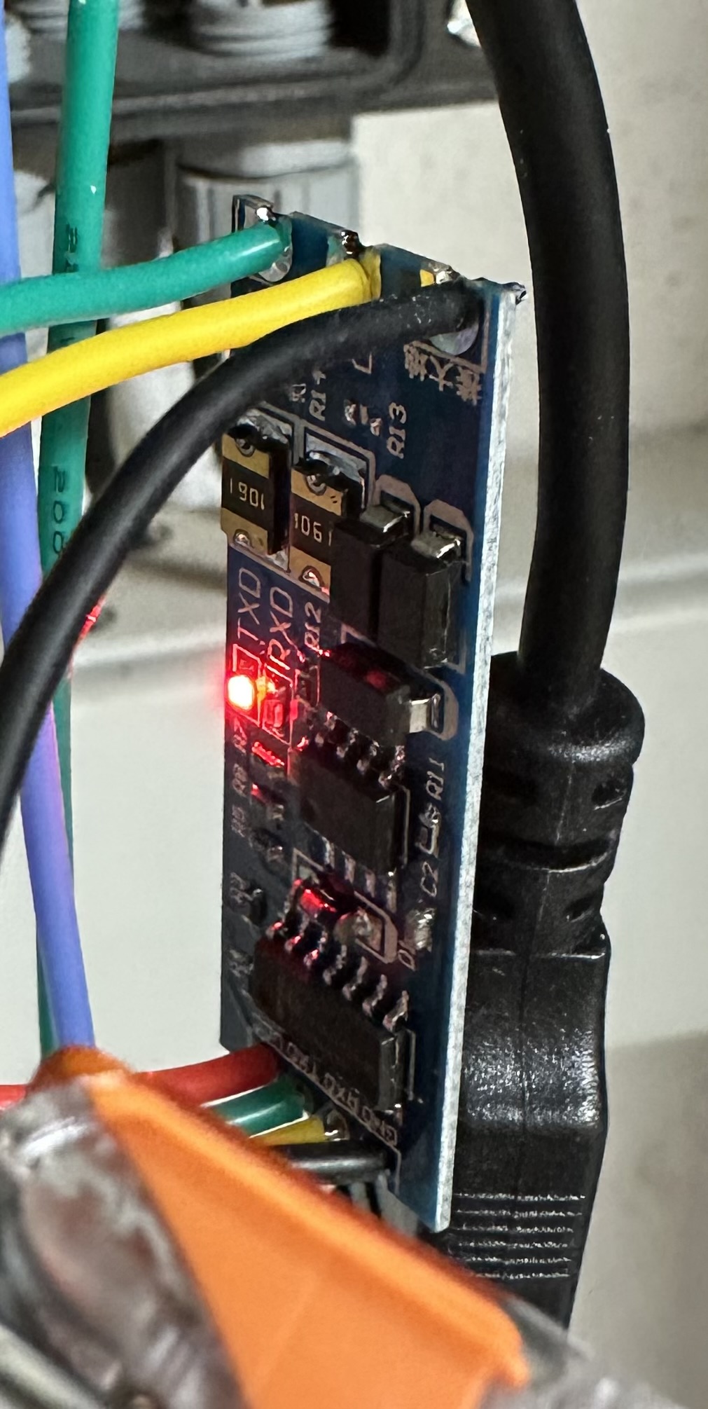
Hi Georg,

ich habe Dein Programm noch nicht ganz durch gearbeitet, deshalb auf die
Schnelle hier die Frage:

Meinst Du, ich kann Dein Programm mit dem Controller aus dem Anhang
verwenden?

Er nutzt wohl FlowControl, Du schaltest die PINs selber, oder?

Hintergrund: ich baue mir gerade ein zweites Set auf und habe diesen
Controller geliefert bekommen, er macht aber erstmal nur TX an und das
war es dann.

Danke!
Da ich weder IC-Beschriftungen noch einen Schaltplan sehe, kann ich gar
nichts dazu sagen.
Angehängte Dateien:
-

IMG_6854.jpeg
230 KB
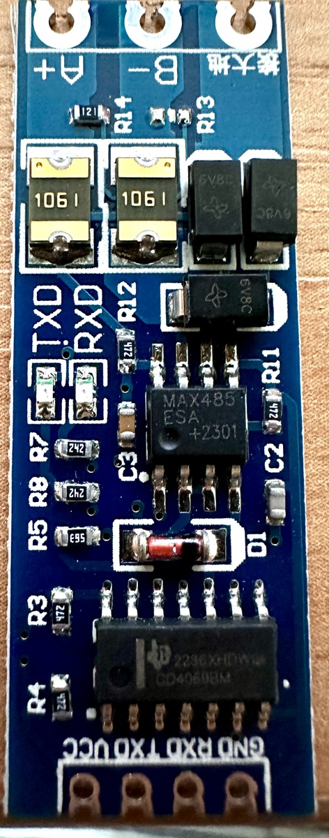
Ich habe es noch mal etwas besser versucht, man kann den Chip erkennen.
Bei R13 kann man wohl eine Brücke setzen, um den 120 Ohm Widerstand zu
aktivieren, ich weiß nicht, ob es den braucht. Einen Schaltplan habe ich
nicht.
Ich denke, es ist nicht die Frage, ob der Transceiver das kann, meine
Frage war, ob Dein Programm auf dem ESP32 ins Nichts läuft, wenn der
Transceiver das Senden und Empfangen automatisch macht/regelt.
Ich bin leider nicht so weit mit diesem Thema und manche Frage mag
komisch sein, aber ich habe unglaublich Lust, dabei was zu lernen und
selber weiter zu kommen.
Dazu brauche ich aber oft erst mal was “zum Anpacken”, um dann weiter
machen zu können.
Es steckt keine Faulheit meinerseits dahinter, bevor das falsch
verstanden wird.
Ich kanns dir jetzt gar nicht sagen, was genau passiert.
Probiers einfach mal und dann kann ich dir vllt tips geben wie das
debuggst :)
Angehängte Dateien:
-

2023-07-24_21h40_34.png
5,4 KB
Ist das im Anhang eine Antwort auf die EBus Abfrage?
Angehängte Dateien:
-

2023-07-24_22h00_12.png
15 KB -

2023-07-24_22h01_15.png
110 KB
Zusätzlich passiert das, wenn man eine EBus Anfrage an die BBU sendet.
Angehängte Dateien:
-

IMG_6868.jpeg
240 KB
Ich habe nun meine Platine fertig gemacht, es bleibt bei dem alten
Controller. Mit dem neuen FlowControl Device wollte ich die restlichen
CRC Fehler ausmerzen, aber ich denke, es ist gut genug so.
Konnte eine meiner Netzteil Platinen verwenden, um so direkt die 12V
abzugreifen und das Ganze in ein Leergehäuse zu bauen, läuft jetzt
prima.

Leider komme ich nicht weiter, was Steuerung etc. angeht. Da muss ich
mal sehen, wie ich da hinter komme, was noch möglich ist. Schön wäre
wirklich, die Uhrzeit setzen zu können (da probiere ich gerade die Tips
oben aus) und zB die Anforderung für Warmwasser triggern zu können.
Mir fehlt noch immer das Verständnis, das zu übersetzen, was ich zB in
Wireshark sehen kann.

Die Windhager truncated Messages tauchen aber nur auf, wenn ich einen
Nachricht sende, die im Tool von Georg unter EBus gespeichert ist. Dazu
muss ich Sender und Empfänger anpassen, dann kommt was zurück.
Hallo,

ich habe noch eine konkrete Frage, da wir diese Funktion oft benötigen:

Ist es möglich, die (oder ähnliche) Funktion: "Jetzt Wasser erwärmen" zu
steuern bzw. über den Bus anzutriggern?

Wenn ja: wie finde ich die Funktion bzw. kann diese so mitschneiden,
dass ich sie reproduzieren kann?

Ich würde gerne den Befehl über iobroker senden, um nicht in den Keller
zu müssen und dies per Hand zu erledigen.

Falls es Hilfe gibt: bitte eine kurze Step-by-Step Anleitung, da ich so
nicht weiterkomme und irgendwie auch nicht weiß, wo ich noch suchen
soll.

Vielen Dank,
Ron
Hi,

nächste Frage: kann man die EBus Anfragen / Auswertung auch Wireshark
fähig machen?

Hintergrund: wenn LON nur Variablen enthält muss ich ja versuchen die
EBus Befehle mitzulesen um zB. den Befehl zur Wassererwärmung
reproduzieren zu können.

So stehe ich immer noch am Anfang mit den Befehlen. So schön die
Erweiterung von Georg um EBus in dem LON Scanner auch ist, ich weiß
nicht, ob ich damit weiter komme, ich brauche ja eigentlich erstmal den
Befehl, der von der Steuerung gesendet wird, wenn man die Funktion am
Bedienteil einschaltet...

Danke,
Ron
Hallo zusammen,

nachdem ich nun mein Projekt erfolgreich abschliessen konnte, wollte ich
mich noch einmal bedanken:

Danke an Georg, für die tolle Inspiration und die Vorgaben.
Danke an Peter, für die eingebrachten Tipps.
Danke an meinen Kumpel, der mich wahrlich bei der Programmierung
unterstützt hat.

Leider habe ich hier keine Reaktionen mehr erhalten, vielleicht war ich
auch zu fordernd, keine Ahnung.

Jedenfalls habe ich:

1.) Den ESP Teil von Georg nachgebaut und erstmal damit getestet.

2.) Die Firmware der Paradigma MES in allen Teilen zerlegt.

3.) Den ESP in großen Teilen umprogrammiert.

4.) Den LON Bus so weit wie möglich zerlegt und analysiert.

Was habe ich erreicht:

1.) Ich kenne nun alle Variablen der Paradigma MES Module 4,8,10,11
(BBU, Solar, 2x C1 UML)

2.) Ich weiß, wie ich den LON beeinflussen kann

3.) Ich kann alle mir wichtigen Funktion steuern oder einbringen, sowohl
Alarm bei zu hoher Solar Temperatur, als auch die Warmwasser
Ansteuerung, kann mit Timings umgehen und auch den LON aushebeln etc.

4.) Ich habe unglaublich viel gelernt und bin froh, nicht aufgegeben zu
haben.

Was ich noch nicht kann:

1.) Die Uhrzeit der Module -> das Thema macht micht irre... Aber ich
werde mit ein wenig Pause dort weitermachen und mich noch dran setzen,
es muss auch möglich sein, das zu beeinflussen...

Viele Grüße, alles Gute, Danke,
Ron
Servus,

gute Arbeit, dann hast du ja das Beste draus gemacht.
 - Was gelernt
 - Dein Ziel erreicht
 - Es selbst erreicht!

Naja zu den Fragen hat wohl keiner pauschale Antworten.
Ich muss sagen, ich hab die letzten auch nicht wirklich gesehen :)

Ich weiss leider auch noch nicht, wie ich meine Bedienteile ansprechen
kann.
EBus scheint es nicht zu sein. Jedenfalls reagiert da nichts drauf.

Magst vllt deine Firmware auch irgendwo online stellen?
So kann der nächste Paradigma-Nutzer vllt draus was machen.

Gruß,
Georg
Ist schon cool, dass ich jetzt am iPad über einen Button mit iobroker
das Wasser erwärmen kann :-)

Die Fragen waren hauptsächlich dazu gedacht, am Ende Aufwand und Zeit zu
sparen, ich habe da echt viele Stunden  dran gesessen.

Ich kann gerne meine Erfahrungen zusammenfassen und dann Online stellen,
aber dazu muss ich alles aufräumen und noch den letzten Teil fertig
bekommen.

Es macht einfach Spaß gerade… :-)
Angehängte Dateien:
-

Windhager_BioWin_2_Touch.png
470 KB
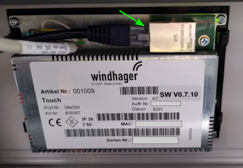
Martin schrieb:
> Windhager Biowin 2

Hi Martin,
Liebe BioWin 2 Touch -Nutzer,

Mir war folgende Info lange Zeit nicht klar und hätte beinahe dazu
geführt dass ich mir ein extra RC-7030 LON-Adapter besorge.

Zumindest die BioWin 2 Touch hat hinter der Display-Einheit einen
LAN-Buchse (Siehe Bild).
Offensichtlich ist der RC-7030 schon integriert und muss nicht extra
gekauft werden.

BG
Wil
Georg H. schrieb:
> Ich hab mir mittlerweile einen Home Assistant eingerichtet und baue
> langsam meine MQTT-Geräte so um, dass sie dem HA die config-messages
> gleich mitschicken.
>
> So hab ich das jetzt auch bei MES-WiFi gemacht.

Lieber Georg,

Bei meiner BioWin2-Touch habe ich schon LAN-Zugriff auf den Webserver.
Damit ist für mich MESWiFi nicht notwendig (obwohl es sehr cool ist!).
Ist deine Integration in Home Assistant aber in irgendeiner Art
kompatibel mit dem Zugriff über LAN?

Zwei Projekte die sich mit dem Zugriff von HA auf die BioWin
beschäftigen sind:
- https://github.com/vermi0ffh/ha-windhager /
https://community.home-assistant.io/t/windhager-integration/348369/11
- https://github.com/sessl3r/windhager/tree/master braucht noch eine
separate VM für die Bereitstellung der Daten als über MQTT
Wobei ich noch nicht beurteilen kann ob diese Integrationen stabiler,
umfangreicher sind als deine.

Aus meiner Sicht wäre natürlich eine Kompatibilität hinsichtlich einer
aktuellen und breite Unterstützung/Wartung, Robustheit und Einfachheit
wünschenswert.

Ist aus deiner Sicht so etwas denkbar? Alternativ würde ich ansonsten
erstmals auf https://github.com/vermi0ffh/ha-windhager setzen.

BG
Wil
Wil schrieb:
> https://github.com/sessl3r/windhager/tree/master braucht noch eine
> separate VM für die Bereitstellung der Daten als über MQTT
> Wobei ich noch nicht beurteilen kann ob diese Integrationen stabiler,
> umfangreicher sind als deine.

Servus Wil,

da bei mir die HA-Integration eher so ein "ich schick die Daten halt auf
MQTT raus" ist, mit ein bisschen Zusatzinfo bzgl der Datenformate etc,
glaub ich nicht, dass es Sinn macht, bei mir da was in der Richtung zu
erweitern.

Ich empfehle dir das von dir genannte Projekt zu nutzen.
Das scheint dann wohl Explizit dafür gemacht und dadurch die bessere
Wahl.
Hallo,

hat schon jemand Erfahrung mit den neuen Infinity Plus Modulen von
Windhager? Die Lon Schnittstelle wurde anscheinend durch Ethernet
ersetzt.
Ich bekomme die Tage das Update auf den Biowin2 und möchte das ganze
dann auch in den HA einbinden. Bzw. suche immer noch nach einer sauberen
Lösung um die Heizkreise in den Absenkbetrieb zu versetzen, wenn alle
Ventile den FBH geschlossen sind und bei Anforderung wieder sauber die
Mischer und Pumpen einzuschalten.

Danke und Grüße
Angehängte Dateien:
-

20231208_214145.jpg
220 KB
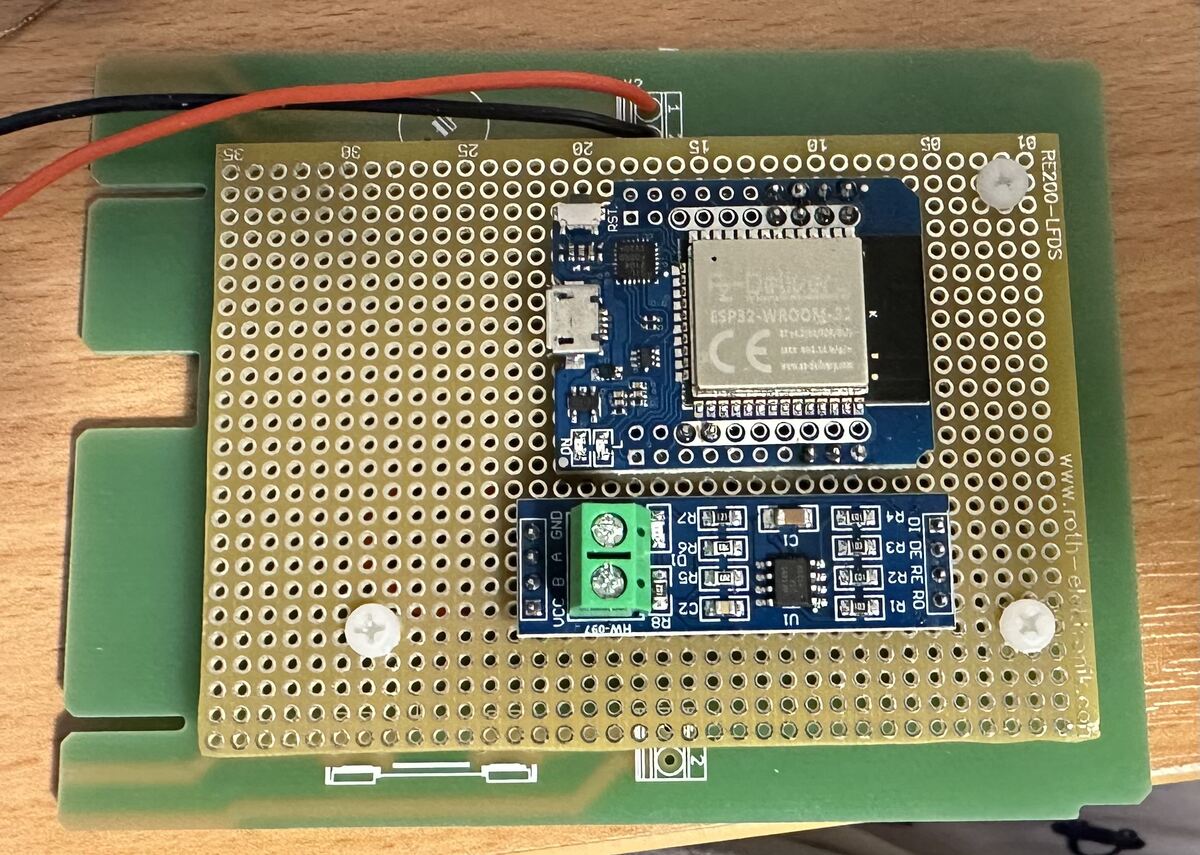
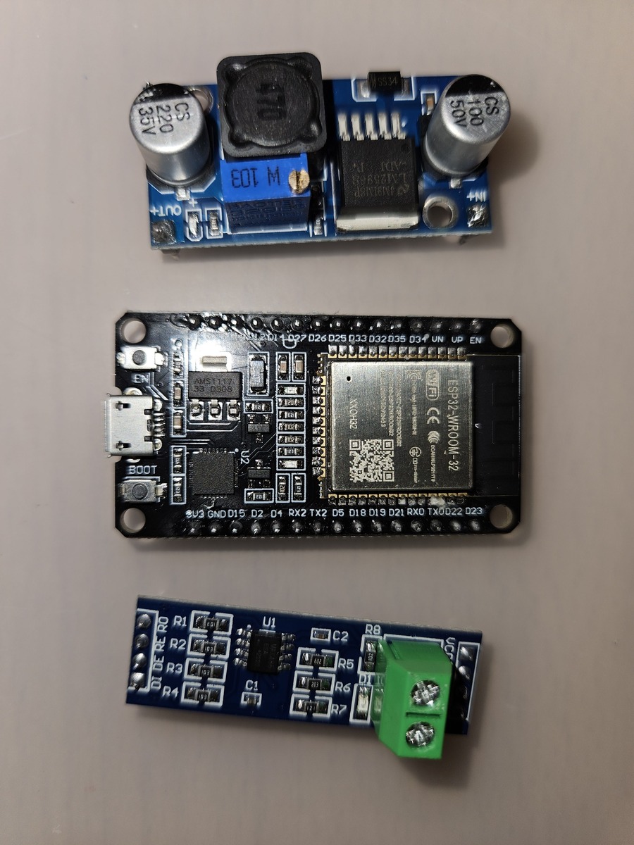
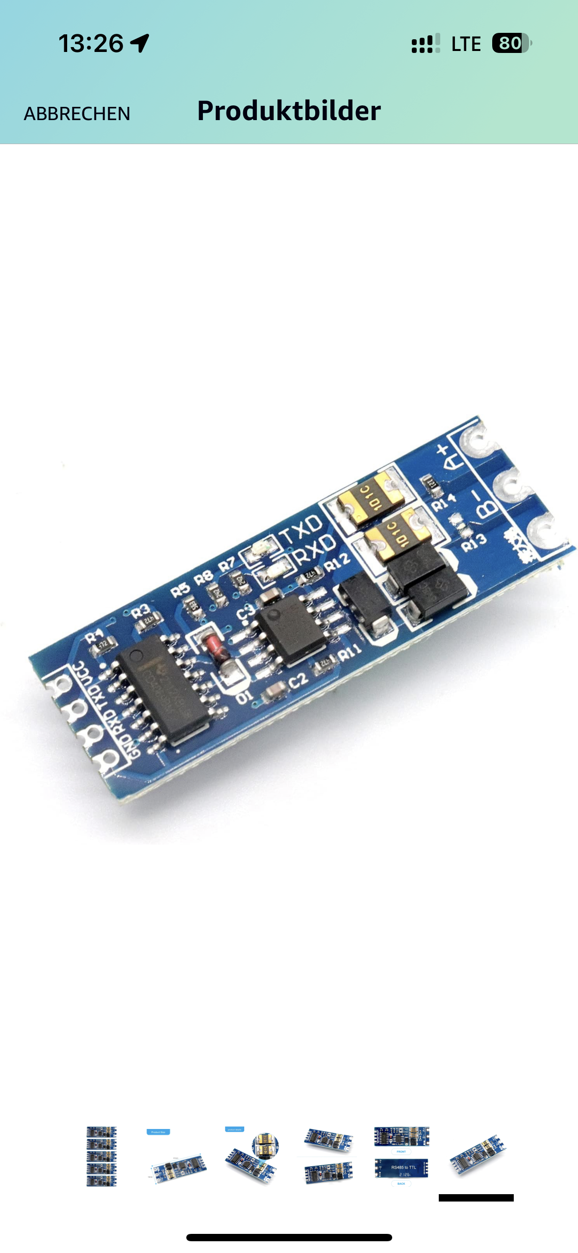
Hallo, ich habe hier ein ESP32-WROOM-32 Board, ein MAX485/RS485 Modul
und ein Step Down Modul auf 5V. Kann ich damit das MES-WiFi von Georg
nutzen? Kann mir da vllt. jemand bei der korrekten Pin-Belegung zwischen
Board und dem MAX485/RS485 Modul helfen? Ich war da bis jetzt leider
erfolglos. Der MES-WiFi Server auf dem ESP32 läuft immerhin :)
Ok, ich habe weiter oben folgende Pin-Belegung gefunden, aber leider
kommt im Home Assistant nichts an.

RO (RX) -> G35
RE/DE (TX_EN) -> G26
DI (TX) -> G25

Der ESP32 connected sich mit dem MQTT-Server, das sehe ich im Home
Assistant-Log. Hat der MES-WiFi Server auch ein Log?
Georg H. schrieb:
> Ich hab mir die OperationalData.xml für die "UML +" angekuckt.
> Dort sieht man schön die EBus IDs
>
> https://github.com/g3gg0/LonScan/releases/tag/v0.4.2
> Hab mal PacketForge etwas erweitert, so dass man die EBus IDs sehen
> kann.

Hallo Georg,

ich habe ein UML+ und würde gerne mehr über EBus Ids in Erfahrung welche
entsprechend angesprochen werden können. Besteht die Möglichkeit das du
mir die vollständige OperationalData.xml zu bekommen?

VG Stefan
Hallo Leute,

ich möchte auch gerne meine Windhager Heizung etwas modernisieren und
Temperaturen online auslesen.
Nur bin ich jetzt etwas überfordert bei den ganzen Beiträgen und
Ansätzen, sodass ich gefühlt nicht mehr weiß wo vorne und hinten ist.
Bei meiner Recherche ist mir folgendes Produkt aufgefallen. Könnte das
evtl. helfen?

https://www.waveshare.com/usb-to-rs485.htm
Hallo,

Ich hab noch einen Kommunikationsmodul, XLON und AVR Schnittstellen mit
Kabeln zum auslesen von Windhager Regelung zum abgeben.
Bei Interesse einfach melden.
Gruß
Heizi
Hallo,

ich bin wahnsinnig beeindruckt von Georgs Projekt und habe mich daher
gleich hier angemeldet.
Mein Kessel ist ein Vitolig 200, also auch genau baugleich.

Ich möchte mich gerne an einem Nachbau versuchen, damit ich den Kessel
im iobroker darstellen kann. Streng genommen reicht mir Lesen, da  Löten
ist kein Problem, der Programmcode ist eine Herausforderung auf die ich
mich freue.

Leider läuft der EasyEDA-Link zum Plattenlayout zur Rev 1.3 auf der
Projekthomepage in Leere.
(https://www.g3gg0.de/default/mes-wifi-bringing-a-windhager-pellet-heater-online/)

Hat jemand die Datei oder Georg, könntest du Sie freundlicherweise
nochmal einstellen?

Beste Grüße
Thomas
Oha, da wurde das Projekt wohl offline genommen.
Habe die Beschreibung aktualisiert und neu eingestellt :)

Hab die Schematic mal angehängt.
Heut würd ich das mit dem ESP32-C6 machen.
Die Frage mutet jetzt wahrscheinlich super amateurhaft an. Ich wollte
heute versuchen die Platine online fertigen zu lassen. Allerdings
bekomme ich aus den pdfs im zip-File kein gerber-Format. Meine Versuche
in EasyEDA zu importieren (sozusagen mein erstes Mal) scheitern an
Fehlermeldungen zu den Inhalten der zip.
Bin ich einfach zu weit am Beginn der Lernkurve, oder stimmt etwas mit
dem zip nicht?

PS. https://oshwlab.com/g3gg0.de/esp32-mes-wifi läuft weiterhin auf "The
project you are trying to access is either unpublished or does not
exist."

Beste Grüße
Thomas
habs nochmal published:
"Submission successful! Please wait for backend review!"
anscheinend klappt das nicht so zuverlässig...

Hier sind die Altium/EasyEDA schematic/board PDFs:
https://www.g3gg0.de/wp-content/uploads/2026/04/MES-WiFi.7z

Heute würde ich das deutlich anders designen.
ESP32-C6 und andere Spannungsregler - da würde vieles einfacher werden.
:
Bearbeitet durch User
Bitte melde dich an um einen Beitrag zu schreiben. Anmeldung ist kostenlos und dauert nur eine Minute.
Bestehender Account
Schon ein Account bei Google/GoogleMail? Keine Anmeldung erforderlich!
Mit Google-Account einloggen
Mit Google-Account einloggen
Noch kein Account? Hier anmelden.