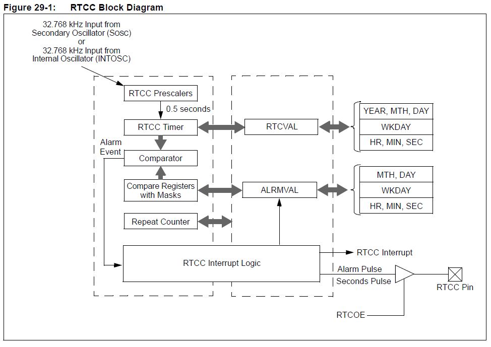
Hallo,

ich habe hier das PIC32 Ethernet Starter kit (bestückt mit PIC32MX795)
und möchte gerne den internen RTC nutzen.

Ich habe noch nie mit einer RTC gearbeitet und mir fehlt auch ein wenig
das Hintergrundwissen dazu. Trotzdem wäre es schön erst einmal Datum,
Zeit etc. auf einem Display darstellen zu können.
Hierfür habe ich mir das RTCC_Code Example von Microchip angeguckt,
welches sich zwar compilieren lässt, aber beim debuggen immer in einer
Schleife hängen bleibt. Diese Schleife scheint zu überprüfen, ob die
Clock des RTC überhaupt läuft.

Irgendetwas scheint also noch faul zu sein. Es gibt noch einen RTCC Pin
am PIC. Wofür genau ist dieser da und wie muss dieser beschaltet werden,
um den internen RTC zu nutzen?

Ich habe einmal das Blockdiagramm des RTCs angehangen.

Danke für jeglichen Input
Angehängte Dateien:
-

Block_RTC_b.JPG
80 KB
H. D. schrieb:
> Einen Quarz hast du?

Kann man da nicht einfach den primären Oszillator für nutzen.

Wenn ich das richtig sehe fehlt auf dem Starterkit ein externer
Sekundäroszillator (32.768 kHz). Dieser scheint standardmäßig nicht auf
dem Board verbaut zu sein. Ist dieser unabdingbar für den internen RTC?
Ich kenn den PIC32 nicht wirklich, aber laut deinem angehängten Diagramm
gibt es beim PIC32 auch einen internen 32kHz Oszillator.
Hast du bei deinem Beispiel mal nachgesehen ob hier der interne
Oszillator auch ausgewählt wird?

Gruß
Rainer
Die externe lohnt nur, wenn du den µC irgendwann abschalten willst, und
das Batteriegepuffert weiterlaufen muss, oder wenn du keinen Clock hast.

Sonst würde ich die interne nehmen. Das hat den Vorteil, dass das
Auslesen der Uhrzeit nur aus ein paar Registerzugriffen besteht, bei der
externen braucht man I2C und wasweisich noch dazu.

Dazu kommen die Alarminterrupts, die sehr praktisch sind.

Kommst du an SOSCI heran? In dem Fall könntest du dir die 32768 Hz
mittels Timer erzeugen und auf den SOSCI-Eingang draufgeben. Wenn man an
beide drankommt (SOSCI + SOSCO), kann man auch einfach eine Uhrenquarz
dranhängen - von einem kaputten Mainboard oder ähnlichem.

Falls gewünscht, kann ich dir heute Abend ein Beispiel für einen
PIC32MX470 zukommen lassen, das sollte sich leicht portieren lassen. Ich
habe es selber geschrieben, weil ich das Beispiel von Microchip nicht
verstanden habe ;-)

Sonst kannst du ja eine DS1337 über I2C oder ähnliches nehmen.
Hallo Rainer,
Hallo WehOhWeh.

Vielen Dank für Eure Hilfe. Ein Beispiel für den PIC32MX470 wäre sehr
nett. Danke dafür.

Ich poste hier mal das Microchip Beispiel. Wie gesagt lässt es sich
compilieren, aber ich bleibe stets an der markierten Stelle hängen:
1 | #include <plib.h> |
2 | #include "time_date.X/displaytech.h" |
3 | |
4 | #if defined (__32MX360F512L__) || (__32MX460F512L__) || (__32MX795F512L__) || (__32MX430F064L__) || (__32MX450F256L__) || (__32MX470F512L__)
|
5 | // Configuration Bit settings
|
6 | // SYSCLK = 80 MHz (8MHz Crystal / FPLLIDIV * FPLLMUL / FPLLODIV)
|
7 | // PBCLK = 80 MHz (SYSCLK / FPBDIV)
|
8 | // Primary Osc w/PLL (XT+,HS+,EC+PLL)
|
9 | // WDT OFF
|
10 | // Other options are don't care
|
11 | #pragma config FPLLMUL = MUL_20, FPLLIDIV = DIV_2, FPLLODIV = DIV_1, FWDTEN = OFF
|
12 | #pragma config POSCMOD = HS, FNOSC = PRIPLL, FPBDIV = DIV_1
|
13 | #define SYS_FREQ (80000000L)
|
14 | |
15 | |
16 | |
17 | // local function prototypes
|
18 | int CheckRtccRunning(int secWait); |
19 | |
20 | /*********************************************************************
|
21 | * Function: int main(void)
|
22 | *
|
23 | * PreCondition: None
|
24 | *
|
25 | * Input: None
|
26 | *
|
27 | * Output: 1 if everything went on ok, 0 if failed
|
28 | *
|
29 | * Side Effects: None
|
30 | *
|
31 | * Overview: The function is an example of using the RTCC device.
|
32 | |
33 | * Note: None
|
34 | ********************************************************************/
|
35 | int main(void) |
36 | {
|
37 | rtccTime tm, tm1; // time structure |
38 | rtccDate dt, dt1; // date structure |
39 | |
40 | // Configure the device for maximum performance but do not change the PBDIV
|
41 | // Given the options, this function will change the flash wait states, RAM
|
42 | // wait state and enable prefetch cache but will not change the PBDIV.
|
43 | // The PBDIV value is already set via the pragma FPBDIV option above..
|
44 | SYSTEMConfig(SYS_FREQ, SYS_CFG_WAIT_STATES | SYS_CFG_PCACHE); |
45 | |
46 | //***************************************************************
|
47 | // Pins für 16/2 Display und Initialisierung
|
48 | //***************************************************************
|
49 | |
50 | button_in; |
51 | RS_OUT; |
52 | E_OUT; |
53 | DB7_OUT; |
54 | DB7_0; |
55 | DB6_OUT; |
56 | DB6_0; |
57 | DB5_OUT; |
58 | DB5_0; |
59 | DB4_OUT; |
60 | DB4_0; |
61 | E_0; |
62 | |
63 | DelayMs(100); |
64 | lcd_init(); |
65 | |
66 | |
67 | |
68 | RtccInit(); // init the RTCC |
69 | while(RtccGetClkStat()!=RTCC_CLK_ON); // -> HIER BLEIBT DAS PROGRAMM IN DER SCHLEIFE HAENGEN |
70 | |
71 | // wait for the SOSC to be actually running and RTCC to have its clock source
|
72 | // could wait here at most 32ms
|
73 | |
74 | |
75 | |
76 | // when using the RtccSetTimeDate() function, the write operation is enabled if needed and then restored to the initial value
|
77 | // so that we don't have to worry about calling RtccWrEnable()/RtccWrDisable() functions
|
78 | |
79 | // let's start setting the current date
|
80 | {
|
81 | // one way to do it
|
82 | tm.l=0; |
83 | tm.sec=0x30; |
84 | tm.min=0x07; |
85 | tm.hour=0x10; |
86 | |
87 | dt.wday=2; |
88 | dt.mday=0x16; |
89 | dt.mon=0x01; |
90 | dt.year=0x07; |
91 | RtccSetTimeDate(tm.l, dt.l); |
92 | }
|
93 | // however, much easier to do it should be:
|
94 | RtccSetTimeDate(0x10073000, 0x07011602); // time is MSb: hour, min, sec, rsvd. date is MSb: year, mon, mday, wday. |
95 | // please note that the rsvd field has to be 0 in the time field!
|
96 | |
97 | // NOTE: at this point the writes to the RTCC time and date registers are disabled
|
98 | |
99 | // we can also read the time and date
|
100 | tm1.l=RtccGetTime(); |
101 | dt1.l=RtccGetDate(); |
102 | // can check that the time and date are the ones we just set
|
103 | if(tm.hour!=tm1.hour ||tm.min!=tm1.min) |
104 | {
|
105 | return 0; |
106 | }
|
107 | if(dt.l!=dt1.l) // check for proper date |
108 | {
|
109 | return 0; |
110 | }
|
111 | // we can read the time and date in a single operation
|
112 | RtccGetTimeDate(&tm1, &dt1); |
113 | |
114 | // now that we know the RTCC clock is up and running, it's easier to start from fresh:
|
115 | RtccOpen(tm.l, dt.l, 0); // set time, date and calibration in a single operation |
116 | |
117 | // check that the RTCC is running
|
118 | if(!CheckRtccRunning(3)) |
119 | {
|
120 | return 0; |
121 | }
|
122 | |
123 | // another way to see the RTCC is tunning: check the SYNC bit
|
124 | while(RtccGetSync()); // wait sync to be low |
125 | while(!RtccGetSync()); // wait to be high |
126 | while(RtccGetSync()); // wait sync to be low again |
127 | |
128 | |
129 | // other RTCC operations
|
130 | |
131 | // adjust the RTCC timing
|
132 | RtccSetCalibration(200); // value to calibrate with at each minute |
133 | |
134 | // enabling the RTCC output pin
|
135 | RtccSelectPulseOutput(1); // select the seconds clock pulse as the function of the RTCC output pin |
136 | RtccSelectPulseOutput(0); // select the alarm pulse as the function of the RTCC output pin |
137 | RtccOutputEnable(1); // enable the Output pin of the RTCC |
138 | set_cursor(0, 1); |
139 | lcd_out("24 Bit AD: "); |
140 | integerintoasciiconverter(RtccGetTime()); |
141 | while(1) |
142 | {
|
143 | |
144 | }
|
145 | |
146 | |
147 | }
|
148 | |
149 | |
150 | |
151 | /*********************************************************************
|
152 | * Function: int CheckRtccRunning(int secWait)
|
153 | *
|
154 | * PreCondition: None
|
155 | *
|
156 | * Input: None
|
157 | *
|
158 | * Output: 1(true) if test succeeded, 0(FALSE) otherwise
|
159 | *
|
160 | * Side Effects: None
|
161 | *
|
162 | * Overview: The function checks that the RTCC has the clock enabled and counts the time.
|
163 | *
|
164 | * Note: None
|
165 | ********************************************************************/
|
166 | int CheckRtccRunning(int secWait) |
167 | {
|
168 | #define WAIT_FOR_SEC_TMO 1100 // how many ms to wait for the RTCC seconds count to change
|
169 | |
170 | rtccTime t0, t1; |
171 | int fail; |
172 | int secCnt; |
173 | unsigned int tStart; |
174 | |
175 | |
176 | |
177 | for(secCnt=0, fail=0; secCnt<secWait; secCnt++) |
178 | {
|
179 | tStart=ReadCoreTimer(); |
180 | t0.l=RtccGetTime(); |
181 | do
|
182 | {
|
183 | t1.l=RtccGetTime(); |
184 | }while((t1.sec == t0.sec) && (ReadCoreTimer()-tStart) < (SYS_FREQ/2000)*WAIT_FOR_SEC_TMO); // wait seconds change |
185 | |
186 | if(t1.sec==t0.sec) |
187 | {
|
188 | fail=1; |
189 | break; // failed |
190 | }
|
191 | }
|
192 | |
193 | return !fail; |
194 | }
|
Ich habe jetzt keinen externen Quarz an das Board angehangen!

Es ist auf dem Starterkit aber ein (Connector Y3) Footprint vorgesehen,
um einen externen sekundären Oszillator anzuhängen. Dies müßten SOSC1
und SOSCO sein. Dieser ist aber nicht bestückt.

Meine Frage ist jetzt, ob ich zunächst einen ähnlichen Oszillator
anlöten muss um das RTC Modul auslesen zu können?

Danke nochmal an Alle für die Hilfe!
Sven der Schreckliche schrieb:
> Ich habe jetzt keinen externen Quarz an das Board angehangen!

Das muss du dem Pic auch sagen (über ein config register).

Main clock läuft mit 20 Mhz, also gibt es vermutlich einen internen 32
kHz Oszillator. Interne sind aber per se ungenau (sonst würde niemand
externe Quarze nutzen). Ein Prozent sind da schon sehr gut, was auf 36
Sekunden pro Stunde hinaus läuft.
Zeig mal die RtccInit().
Irgendwo muss ja gesagt werden ob der interne oder der externe Clock
genutzt werden soll.
Frank schrieb:
> Zeig mal die RtccInit().
1 | /*********************************************************************
|
2 | * Function: rtccRes RtccInit(void)
|
3 | *
|
4 | * PreCondition: None
|
5 | *
|
6 | * Input: None
|
7 | *
|
8 | * Output: RTCC_CLK_ON if the RTCC clock is actually running
|
9 | * a clock status code otherwise
|
10 | *
|
11 | * Side Effects: None
|
12 | *
|
13 | * Overview: The function initializes the RTCC device. It starts the RTCC clock,
|
14 | * enables the RTCC and disables RTCC write. Disables the Alarm and the OE.
|
15 | * Clears the alarm interrupt flag and disables the alarm interrupt.
|
16 | *
|
17 | * Note: It usually takes 4x256 clock cycles (approx 31.2 ms) for the oscillator signal to be available
|
18 | * to the RTCC. The user must make sure that the clock is actually running using RtccGetClkStat()
|
19 | * before expecting the RTCC to count.
|
20 | *
|
21 | * Example: rtccRes res=RtccInit();
|
22 | ********************************************************************/
|
23 | rtccRes RtccInit(void); |
24 | |
25 | /*********************************************************************
|
26 | * Function: rtccRes RtccOpen((unsigned long tm, unsigned long dt, int drift)
|
27 | *
|
28 | * PreCondition: tm an unsigned long containing the fields of a valid rtccTime structure:
|
29 | * - sec: BCD codification, 00-59
|
30 | * - min: BCD codification, 00-59
|
31 | * - hour: BCD codification, 00-24
|
32 | * dt is an unsigned long conatining the valid fields of a rtccDate structure:
|
33 | * - wday: BCD codification, 00-06
|
34 | * - mday: BCD codification, 01-31
|
35 | * - mon: BCD codification, 01-12
|
36 | * - year: BCD codification, 00-99
|
37 | * drift has to fit into signed 10 bits representation
|
38 | *
|
39 | * Input: tm - the time value to be set
|
40 | * dt - the date value to be set
|
41 | * drift - value to be added/subtracted to perform calibration
|
42 | *
|
43 | * Output: RTCC_CLK_ON if the RTCC clock is actually running
|
44 | * a clock status code otherwise
|
45 | *
|
46 | * Side Effects: None
|
47 | *
|
48 | * Overview: The function initializes the RTCC device. It starts the RTCC clock, sets the desired time and calibration
|
49 | * and enables the RTCC. Disables the Alarm and the OE and further RTCC writes.
|
50 | * Clears the alarm interrupt flag and disables the alarm interrupt.
|
51 | *
|
52 | * Note: It usually takes 4x256 clock cycles (approx 31.2 ms) for the oscillator signal to be available
|
53 | * to the RTCC. The user must make sure that the clock is actually running using RtccGetClkStat()
|
54 | * before expecting the RTCC to count.
|
55 | *
|
56 | * Example: rtccDate dt; dt.wday=05; dt.mday=0x28; dt.mon=0x2; dt.year=0;
|
57 | * rtccTime tm; tm.sec=0x15; tm.min=0x30; tm.hour=01;
|
58 | * rtccRes res=RtccOpen(tm.l, dt.l, 10);
|
59 | * or
|
60 | * rtccRes res=RtccOpen(0x01301500, 0x00022805, 10);
|
61 | ********************************************************************/
|
62 | rtccRes RtccOpen(unsigned long tm, unsigned long dt, int drift); |
>The user must make sure that the clock is actually running using
>RtccGetClkStat() before expecting the RTCC to count.
Frank schrieb:
> Debug mal und schau wasrtccRes res=RtccInit();
> zurück gibt.

es wird

RTCC_SOSC_NRDY,      // SOSC not running

zurückgegeben.

Er scheint also den sekundären Quarz zu erwarten, welcher bei mir ja
nicht bestückt ist.

Habe jetzt einfach mal einen bestellt.
anbei das Beispiel für den MX470.

Das ist halt nicht konfigurierbar wie die Microchip Libs, sondern deckt
nur meinen Bedarf ab (Alarm, RTCC, Zeit setztn / lesen). Ich hab das vor
langer, langer Zeit für einen PIC24 geschrieben und dann portiert. Es
erhebt keinen Anspruch auf Eleganz :-)

Relevant sind die RTCC.* files, in "GlobalDefinitions.h" sind nur 2
defines und ein paar typedefs relevant.

Ich verwende immer ein Struct namens TIME für die Zeiten, die Funktionen
bekommen einen Pointer da drauf.

initrtcc();
Das macht die RTCC an. Clock ist SOSC, ich hab einen Uhrenquarz dran.

GetTimeDate(Time *Output);
liest Zeit und Datum aus und schreibt sie in Output

SetTimeDate(Time *IN);
stellt die Zeit
Warnung:
Da ist ein while ohne Timeout drin. Das will man vielleicht nachrüsten.
Ich brauch es nicht, weil ohne funktionerende RTCC geht bei mir nichts,
nicht mal das Display.

SetAlarm(Time *IN, uint8_t interval, uint8_t ena);
Sinnvoll für den Interrupt, man kann einen Alarm setzen. Getestet habe
ich (mangels Geduld) nur 1s, 10s, 1min.
Das interval ist das Setting für AMASK (siehe Datenblatt PIC).
mit g_enable schaltet man den Interrupt ein, mit g_disable aus.
Auch hier, ein Timeout fehlt.

void __ISR(_RTCC_VECTOR,ipl6) _RTCCInterrupt(void)
Die ISR. Die setzt nur ein Jobflag. Alles weitere passiert in einem
Eventhandler.

Für die Funktion kann ich nicht garantieren, es läuft aber seit >1Jahr
in meiner Wetterstation.
Hallo WehOhWeh,

recht herzlichen Dank. Ich werde am WE versuchen direkt versuchen das
auf meinen PIC zu implementieren. Sehr nett und nicht
selbstverständlich, dass Du mir hier deinen Code zur Verfügung stellst!
Ich benutze als RTC einfach einen 1s Timerinterrupt, der eine 32Bit
Variable hochzählt.
Damit lassen sich sehr einfach Zeiten vergleichen, z.B. für Steuerungen.
Und nur zur Anzeige für den Menschen gibt es eine Routine zur
Umwandlung.
Bei einem 32Bitter muß man den Zugriff auf die Zeit-Variable nichtmal
mehr atomar kapseln.
Ich habe doie RTC Clock (intern) jetzt implementiert. Ich bräuchte jetzt
natürlich noch eine Pufferbatterie etc. weiß Jemand welche man dafür am
besten beim PIC Starterkit nutzt, an welche Pins etc.?
Bitte melde dich an um einen Beitrag zu schreiben. Anmeldung ist kostenlos und dauert nur eine Minute.
Bestehender Account
Schon ein Account bei Google/GoogleMail? Keine Anmeldung erforderlich!
Mit Google-Account einloggen
Mit Google-Account einloggen
Noch kein Account? Hier anmelden.