1 | /*
|
2 | * This example sets up the UART to send data to and receive data from the laptop
|
3 | * When the data is received, an interrupt occurs and the data will then be taken from the buffer
|
4 | */
|
5 | #include "DSP28x_Project.h" // Device Headerfile and Examples Include File
|
6 | __interrupt void UART_isr(void);
|
7 |
|
8 | void scia_init();
|
9 | void scia_xmit(int a);
|
10 | void scia_msg(char *msg);
|
11 | Uint16 bla;
|
12 | Uint16 ReceivedChar;
|
13 | char *msg;
|
14 |
|
15 | #define UART_MAXSTRLEN 10
|
16 | volatile Uint16 uart_str_complete = 0; // 1 .. String komplett empfangen
|
17 | volatile Uint16 uart_str_count = 0;
|
18 | volatile char uart_string[UART_MAXSTRLEN + 1] = "";
|
19 |
|
20 |
|
21 |
|
22 | void main(void) {
|
23 |
|
24 | ReceivedChar=0;
|
25 | bla=0;
|
26 |
|
27 | // Step 1: Setting the PLL, Watchdog, enable peripheral clocks
|
28 | InitSysCtrl();
|
29 |
|
30 | // Step 3: Initialize the PIE control registers
|
31 | // DINT; // Only necessary here if InitPieCtrl() does not have DINT; included
|
32 | InitPieCtrl();
|
33 |
|
34 | IER = 0x0000;
|
35 | IFR = 0x0000;
|
36 |
|
37 | // Step 4: Initialize the PIE vector table to default ISR
|
38 | InitPieVectTable();
|
39 |
|
40 | // Configure the interrupt handling
|
41 | // Setting up the XINT1 trigger, Table 112
|
42 | EALLOW;
|
43 | PieVectTable.SCIRXINTA = &UART_isr;
|
44 | EDIS;
|
45 |
|
46 | // Enable XINT1 in the PIE
|
47 | // PieCtrlRegs.PIECTRL.bit.ENPIE = 1; // Enables the PIE interrupt table. Already done in InitPieVectTable();
|
48 | PieCtrlRegs.PIEIER9.bit.INTx1 = 1; // Figure 87
|
49 | IER |= M_INT9; // Sets the interrupt enable bit of group 9
|
50 | EINT; // Enable global interrupts INTM
|
51 | // Step 5: Initialize other device peripherals
|
52 |
|
53 | // We need to initialize our SCI
|
54 | InitSciGpio();
|
55 |
|
56 | // Step 6: Write your code
|
57 | scia_init(); // Initialize Sci FIFO
|
58 | msg = "\r\nHello Alexander!\0";
|
59 | scia_msg(msg);
|
60 |
|
61 | msg = "\r\nHow are you?\0";
|
62 | scia_msg(msg);
|
63 |
|
64 | for(;;)
|
65 | {
|
66 | // Wait for inc character
|
67 | while(SciaRegs.SCIFFRX.bit.RXFFST !=1) { } // wait for XRDY =1 for empty state
|
68 | }
|
69 | }
|
70 |
|
71 | void scia_init()
|
72 | {
|
73 | /*
|
74 | * FIFO configuration
|
75 | */
|
76 | // SCIFFTX registers
|
77 | SciaRegs.SCIFFTX.bit.SCIRST = 1; // Sci reset
|
78 | SciaRegs.SCIFFTX.bit.SCIFFENA = 1; // Sci enhancements enabled
|
79 | SciaRegs.SCIFFTX.bit.TXFIFOXRESET = 1; // Re-enable transmit FIFO operation
|
80 | SciaRegs.SCIFFTX.bit.TXFFST = 0; // Transmit FIFO is empty
|
81 | SciaRegs.SCIFFTX.bit.TXFFINTCLR = 1; // Clears TXFFINT flag
|
82 | SciaRegs.SCIFFTX.bit.TXFFIENA = 0; // TX FIFO interrupt is disabled
|
83 |
|
84 | // SCIFFRX registers
|
85 | SciaRegs.SCIFFRX.bit.RXFIFORESET = 1; // Re-enable receive FIFO operation
|
86 | SciaRegs.SCIFFRX.bit.RXFFINTCLR = 1; // Clears RXFFINT flag
|
87 | SciaRegs.SCIFFRX.bit.RXFFIENA = 1; // RX FIFO interrupt is enabled
|
88 | // SciaRegs.SCIFFRX.bit.RXFFIL = 0x1F; // 1111
|
89 |
|
90 | // SCIFFCT registers
|
91 | SciaRegs.SCIFFCT.all = 0; // Lets leave it as it is for now
|
92 |
|
93 | /*
|
94 | * Echoback configuration
|
95 | */
|
96 | // SCICCR registers
|
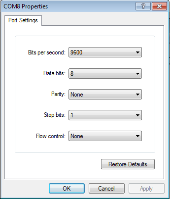
97 | SciaRegs.SCICCR.bit.STOPBITS = 0; // 1 stop bit
|
98 | SciaRegs.SCICCR.bit.PARITY = 0; // Odd Parity - but will be disabled anyways
|
99 | SciaRegs.SCICCR.bit.PARITYENA = 0; // Parity disabled
|
100 | SciaRegs.SCICCR.bit.LOOPBKENA = 0; // Loopback test mode disabled
|
101 | SciaRegs.SCICCR.bit.ADDRIDLE_MODE = 0; // Idle line mode
|
102 | SciaRegs.SCICCR.bit.SCICHAR = 7; // 8 char bits
|
103 |
|
104 | // SCICTL1 registers
|
105 | SciaRegs.SCICTL1.bit.RXERRINTENA = 0; // Receive error interrupt disabled
|
106 | SciaRegs.SCICTL1.bit.SWRESET = 0; // Initializing operating flags to the reset condition
|
107 | SciaRegs.SCICTL1.bit.TXWAKE = 0; // Wake-up mode disabled
|
108 | SciaRegs.SCICTL1.bit.SLEEP = 0; // Sleep mode disabled
|
109 | SciaRegs.SCICTL1.bit.TXENA = 1; // Enable transmitter
|
110 | SciaRegs.SCICTL1.bit.RXENA = 1; // Enable receiver
|
111 |
|
112 | // SCICTL2 registers
|
113 | SciaRegs.SCICTL2.bit.TXRDY = 0; // SCITXBUF is full
|
114 | SciaRegs.SCICTL2.bit.TXEMPTY = 0; // Transmitter buffer is loaded with data
|
115 | SciaRegs.SCICTL2.bit.RXBKINTENA = 1; // Receiver buffer interrupt enabled
|
116 | SciaRegs.SCICTL2.bit.TXINTENA = 1; // TXRDY interrupt enabled
|
117 |
|
118 | // SCIHBAUD registers for BAUD rate
|
119 | SciaRegs.SCIHBAUD =0x0001; // 9600 baud @LSPCLK = 37.5MHz.
|
120 | SciaRegs.SCILBAUD =0x00E7;
|
121 |
|
122 | // SCICTL1 registers again
|
123 | SciaRegs.SCICTL1.all = 0x0023; // WTF?
|
124 | }
|
125 |
|
126 | void scia_xmit(int a)
|
127 | {
|
128 | // Wait until sending is possible
|
129 | while(SciaRegs.SCIFFTX.bit.TXFFST != 0) {}
|
130 | SciaRegs.SCITXBUF = a; // Sending the data
|
131 | bla=a-'0';
|
132 | }
|
133 |
|
134 | void scia_msg(char * msg)
|
135 | {
|
136 | //
|
137 | int i;
|
138 | i = 0;
|
139 | while(msg[i] != '\0')
|
140 | {
|
141 | //
|
142 | scia_xmit(msg[i]);
|
143 | i++;
|
144 | }
|
145 | }
|
146 |
|
147 | __interrupt void UART_isr(void)
|
148 | {
|
149 | // Get character
|
150 | ReceivedChar = SciaRegs.SCIRXBUF.all;
|
151 | if( uart_str_complete == 0 ) { // wenn uart_string gerade in Verwendung, neues Zeichen verwerfen
|
152 |
|
153 | // Daten werden erst in uart_string geschrieben, wenn nicht String-Ende/max Zeichenlänge erreicht ist/string gerade verarbeitet wird
|
154 | if( ReceivedChar != '\n' &&
|
155 | ReceivedChar != '\r' &&
|
156 | uart_str_count < UART_MAXSTRLEN ) {
|
157 | uart_string[uart_str_count] = ReceivedChar;
|
158 | uart_str_count++;
|
159 | }
|
160 | else {
|
161 | uart_string[uart_str_count] = '\0';
|
162 | uart_str_count = 0;
|
163 | uart_str_complete = 1;
|
164 | }
|
165 | }
|
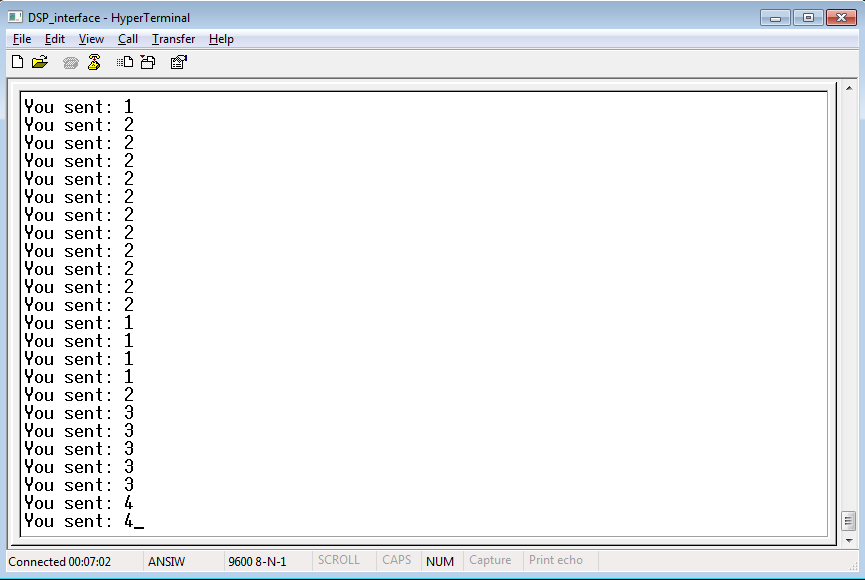
166 | msg = "\r\nYou sent: \0";
|
167 | scia_msg(msg);
|
168 | scia_xmit(ReceivedChar);
|
169 |
|
170 | SciaRegs.SCIFFRX.bit.RXFFOVRCLR=1; // Clear Overflow flag
|
171 | SciaRegs.SCIFFRX.bit.RXFFINTCLR = 1; // Clears RXFFINT flag to enable new incoming interrupts
|
172 | // Acknowledge this interrupt to get more from group 1
|
173 | PieCtrlRegs.PIEACK.all = PIEACK_GROUP9;
|
174 | }
|