Grüßle,
Habe hier ein Problem mit der Portierung der USB-CDC-Lib auf den
STM32F107. Als Grundlage nehme ich das Projekt von hier:
http://mikrocontroller.bplaced.net/wordpress/?page_id=1263
Auf dem F4-Discovery funktionier alles einwandfrei.
Mein F107 Board (Eigenentwicklung, mit 8Mhz Quarz) hat die gleiche
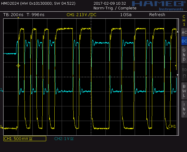
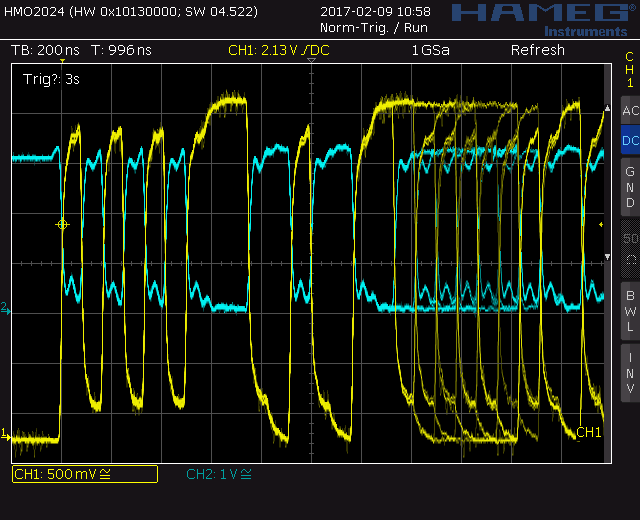
USB-Beschaltung wie das F4-Discovery. Die Signale am USB sieht man im
Anhang. Komisch ist, dass die USB-Signale bei dem 107er Board etwas
"verschliffener" sind.
Hier die USB-Hardware Init, welche sich vom F4 unterscheidet:
1 | void UB_OTG_BSP_Init(USB_OTG_CORE_HANDLE *pdev)
|
2 | {
|
3 | GPIO_InitTypeDef GPIO_InitStructure;
|
4 |
|
5 | RCC_APB2PeriphClockCmd(RCC_APB2Periph_GPIOA | RCC_APB2Periph_AFIO, ENABLE);
|
6 | // RCC_APB1PeriphClockCmd(RCC_APB1Periph_USB, ENABLE) ;
|
7 | RCC_AHBPeriphClockCmd(RCC_AHBPeriph_OTG_FS, ENABLE);
|
8 |
|
9 | // VBUS
|
10 | GPIO_InitStructure.GPIO_Pin = GPIO_Pin_9;
|
11 | GPIO_InitStructure.GPIO_Mode = GPIO_Mode_IN_FLOATING;
|
12 | GPIO_InitStructure.GPIO_Speed = GPIO_Speed_50MHz;
|
13 | GPIO_Init(GPIOA, &GPIO_InitStructure);
|
14 |
|
15 | // DM, DP
|
16 | // Configure PA11, PA12 as USB lines
|
17 | GPIO_InitStructure.GPIO_Pin = GPIO_Pin_11 | GPIO_Pin_12;
|
18 | GPIO_InitStructure.GPIO_Mode = GPIO_Mode_AF_PP;
|
19 | GPIO_InitStructure.GPIO_Speed = GPIO_Speed_50MHz;
|
20 | GPIO_Init(GPIOA, &GPIO_InitStructure);
|
21 |
|
22 |
|
23 | // Enable USB clock for USB FS OTG controller
|
24 | RCC_AHBPeriphClockCmd(RCC_AHBPeriph_OTG_FS, ENABLE) ;
|
25 | }
|
Und die RCC-Init ist auch etwas anders als beim F4:
1 | void MCU_RCC_Config(void)
|
2 | {
|
3 | ErrorStatus HSEStartUpStatus;
|
4 | SystemInit();
|
5 | /* RCC system reset(for debug purpose) */
|
6 | RCC_DeInit();
|
7 | /* Enable HSE */
|
8 | RCC_HSEConfig(RCC_HSE_ON);
|
9 | /* Wait till HSE is ready */
|
10 | HSEStartUpStatus = RCC_WaitForHSEStartUp();
|
11 |
|
12 | if (HSEStartUpStatus == SUCCESS)
|
13 | {
|
14 | /* HCLK = SYSCLK => 72MHz */
|
15 | RCC_HCLKConfig(RCC_SYSCLK_Div1);
|
16 | /* PCLK2 = HCLK => 72Mhz */
|
17 | RCC_PCLK2Config(RCC_HCLK_Div1);
|
18 | /* PCLK1 = HCLK/2 => 36MHz */
|
19 | RCC_PCLK1Config(RCC_HCLK_Div2);
|
20 | /* ADCCLK = PCLK2/6 => 12MHz */
|
21 | RCC_ADCCLKConfig(RCC_PCLK2_Div6);
|
22 | /* USB OTG CLK = PLLVCO / 3 => 48Mhz */ /* PLLVCO = 2*PLL */
|
23 | RCC_OTGFSCLKConfig(RCC_OTGFSCLKSource_PLLVCO_Div3);
|
24 |
|
25 | /* Flash 2 wait state */
|
26 | *(vu32 *)0x40022000 = 0x01;
|
27 |
|
28 | #ifdef STM32F10X_CL
|
29 | // PLL configuration: PLLCLK
|
30 | /* Configure PLLs *********************************************************/
|
31 | /* PLL2 configuration: PLL2CLK = (HSE / 5) * 8 = 40 MHz */
|
32 | RCC_PREDIV2Config(RCC_PREDIV2_Div5);
|
33 | RCC_PLL2Config(RCC_PLL2Mul_8);
|
34 |
|
35 | // Enable PLL2
|
36 | RCC_PLL2Cmd(ENABLE);
|
37 |
|
38 | // Wait till PLL2 is ready
|
39 | while (RCC_GetFlagStatus(RCC_FLAG_PLL2RDY) == RESET);
|
40 |
|
41 | // PLL configuration: PLLCLK = (HSE) * 9 = 72 MHz *
|
42 | RCC_PREDIV1Config(RCC_PREDIV1_Source_HSE, RCC_PREDIV1_Div1);
|
43 | RCC_PLLConfig(RCC_PLLSource_PREDIV1, RCC_PLLMul_9);
|
44 | #else
|
45 | /* PLLCLK = 8MHz * 9 = 72 MHz */
|
46 | RCC_PLLConfig(RCC_PLLSource_HSE_Div1, RCC_PLLMul_9);
|
47 | #endif
|
48 | /* Enable PLL */
|
49 | RCC_PLLCmd(ENABLE);
|
50 | /* Wait till PLL is ready */
|
51 | while (RCC_GetFlagStatus(RCC_FLAG_PLLRDY) == RESET);
|
52 |
|
53 | /* Select PLL as system clock source */
|
54 | RCC_SYSCLKConfig(RCC_SYSCLKSource_PLLCLK);
|
55 | /* Wait till PLL is used as system clock source */
|
56 | while (RCC_GetSYSCLKSource() != 0x08);
|
57 | }
|
58 | }
|
Habe ich da etwas vergessen? Ansonsten ist der USB-OTD-Device lib doch
egal ob F4 oder F107...die interne OTG-Hardware ist ja scheinbar
gleichwertig.

Fakt ist jedoch, dass das F107 Board nur als "Unknown Device" erkannt
wird, währden das F4 Discovery astrein als VCP werkelt.

Bin für hilfreiche Tipps dankbar.