I'm currently trying to implement a FPGA design using a 325 MHz clock,
which writes to the SDRAM Controller of a Cyclone V
5CSEBA6U23I7(http://www.kynix.com/Parts/36331/5CSEBA6U23I7N.html) (Speed
Grade 7).
When running my IP Core with 2 MHz everything works fine, but when I
change the PLL clock to either 200 MHz or 325 MHz the data I can observe
with SignalTap becomes completly random.
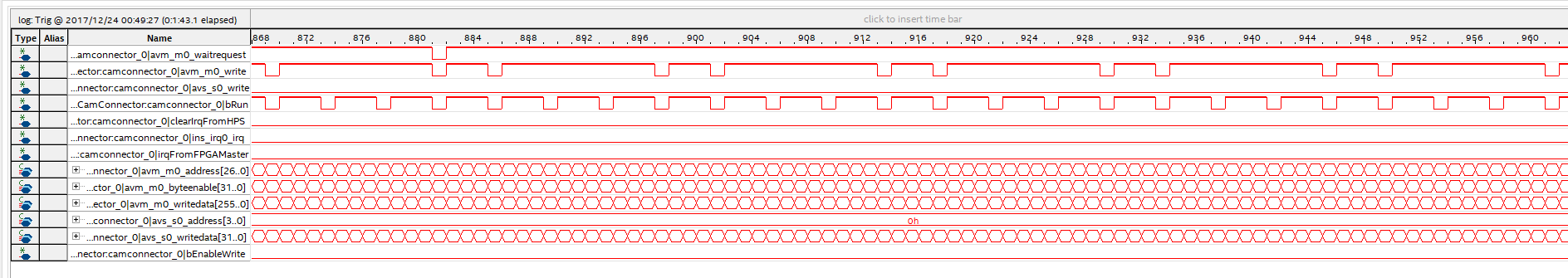
I've attached an image, in which I want to point out the 4th signal
(bRun), which should be constant at 1, but in the observation toggles to
0 and back to 1. Some other signals also experience completly random
behaviour, like some internal busses, which carry non-zero data, when
they should be zero.
I don't think this is an EMC problem, because I'm using a development
board (DE10-Nano from terasic) and all signals are FPGA-internal, which
should be able to handle these clockspeeds.
(See attachment ywkni.png)
The IP-Core is written in Verilog and I made sure to synchronize read
and write operations on different edges of the respective clock to make
sure, that the signals are stable and not transitioning when being read.
Following you can find the code for my RAM-write state machine, but as
stated it works perfectly fine at 2 MHz.
If you guys have any idea about the reason for this behaviour I'd be
very thankful.
1 | imgSize <= imgSize;
|
2 | nCntCurPos <= 4'b0;
|
3 | nOutWord <= 256'b0;
|
4 |
|
5 | fifo_read <= 0;
|
6 |
|
7 | avm_m0_address <= 27'b0;
|
8 | avm_m0_writedata <= 256'b0;
|
9 | avm_m0_write <= 0;
|
10 | avm_m0_byteenable <= 32'b0;
|
11 |
|
12 | irqFromFPGAMaster <= state[2];
|
13 | if(state[2]==0) state <= 3'b000;
|
14 | else state <= state;
|
15 | end
|
16 | endcase
|
17 | end
|
18 | else//Running, but IRQ hasn't been handled yet, preserve some data
|
19 | begin
|
20 | imgSize <= imgSize;
|
21 | irqFromFPGAMaster <= irqFromFPGAMaster;
|
22 | //irqFromFPGAMaster <= 0;
|
23 | //imgSize <= 32'd0;
|
24 |
|
25 | nCntCurPos <= 4'b0;
|
26 | nOutWord <= 256'b0;
|
27 | state <= 3'b0;
|
28 | fifo_read <= 0;
|
29 | avm_m0_address <= 27'b0;
|
30 | avm_m0_writedata <= 256'b0;
|
31 | avm_m0_write <= 0;
|
32 | avm_m0_byteenable <= 32'b0;
|
33 | end
|
34 | end
|
35 | end
|
Also just fyi: The bRun Signal is being assigned by an Avalon MM-Slave
connected to the ARm-Processor of the Cyclone V. During the observed
period there hasn't been any communication with the processor so bRun
shouldn't change. This also wouldn't explain the NRZ bus, which should
be RZ, as seen in the Verilog code.