von
Stefan F. (Gast)
26.04.2018 20:24
Hallo Leute,
ich probiere gerade zum ersten mal die I²C Schnittstelle meines Nucleo64
Boardes mit dem STM32F103RB T6 aus. Zunächst geht es mit um den Master
Modus mit Polling. Mit IRQ und DMA befasse ich mich ein anderes mal.
Der Slave ist ein Ardunino Nano mit einem eilig zusammen geklöppelten
Testprogramm, weil ich gerade keinen anderen Slave da habe. Er simuliert
ein Gerät mit 6 Registern, welche beim Lesen immer die folgenden
hardcodierten Werte liefern (Schreibzugriffe bewirken nichts):
Register 0: 0x10 = 16
Register 1: 0x11 = 17
Register 2: 0x22 = 34
Register 3: 0x44 = 64
Register 4: 0x88 = 136
Register 5: 0xFF = 255
Das Programm soll die ersten 3 Register mit den Werten 1,2,3
beschreiben, danach soll es die ersten 4 Register lesen.
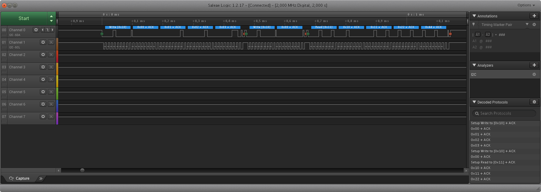
Ich wüsste gerne, ob ich das folgende Programm richtig umgesetzt habe.
Es funktioniert offensichtlich, da ich die erwarteten Testdaten vom
Slave empfange. Auch der Mitschnitt des Logic Analyzers sieht gut aus,
soweit ich das beurteilen kann.
1 #include "stm32f1xx.h"
2
3 // receive buffer
4 uint8_t buffer [ 20 ];
5
6
7 int main ( void )
8 {
9 // Enable Port B and alternate functions
10 SET_BIT ( RCC -> APB2ENR , RCC_APB2ENR_IOPBEN );
11 SET_BIT ( RCC -> APB2ENR , RCC_APB2ENR_AFIOEN );
12
13 // Configure I2C
14 SET_BIT ( RCC -> APB1ENR , RCC_APB1ENR_I2C1EN ); // Enable clock
15 MODIFY_REG ( I2C1 -> CR2 , I2C_CR2_FREQ , 8 ); // Peripheral clock is 8MHz
16 MODIFY_REG ( I2C1 -> CCR , I2C_CCR_CCR , 40 ); // Clock pulse width 5µs+5µs
17 MODIFY_REG ( I2C1 -> TRISE , I2C_TRISE_TRISE , 9 ); // Maximum rise time 1µs (+1)
18 SET_BIT ( I2C1 -> CR1 , I2C_CR1_PE ); // enable the peripheral
19
20 // remap I2C to PB8=SCL, PB9=SDA as alternate function open-drain 2MHz
21 // Must be done after the I2C initialization otherwise the I/O pins
22 // would start with wrong logic level
23 SET_BIT ( AFIO -> MAPR , AFIO_MAPR_I2C1_REMAP );
24 MODIFY_REG ( GPIOB -> CRH , GPIO_CRH_CNF8 + GPIO_CRH_MODE8 ,
25 GPIO_CRH_CNF8_0 + GPIO_CRH_CNF8_1 + GPIO_CRH_MODE8_1 );
26 MODIFY_REG ( GPIOB -> CRH , GPIO_CRH_CNF9 + GPIO_CRH_MODE9 ,
27 GPIO_CRH_CNF9_0 + GPIO_CRH_CNF9_1 + GPIO_CRH_MODE9_1 );
28
29
30 // Send some bytes
31 SET_BIT ( I2C1 -> CR1 , I2C_CR1_START ); // send START condition
32 while ( ! READ_BIT ( I2C1 -> SR1 , I2C_SR1_SB )); // wait until START has been generated
33 WRITE_REG ( I2C1 -> DR , 8 << 1 ); // send 7bit slave address 8
34 while ( ! READ_BIT ( I2C1 -> SR1 , I2C_SR1_ADDR )); // wait until address has been sent
35 READ_REG ( I2C1 -> SR2 ); // clear ADDR
36 WRITE_REG ( I2C1 -> DR , 0 ); // send register no
37 while ( ! READ_BIT ( I2C1 -> SR1 , I2C_SR1_TXE )); // wait until Tx register is empty
38 WRITE_REG ( I2C1 -> DR , 1 ); // send data byte
39 while ( ! READ_BIT ( I2C1 -> SR1 , I2C_SR1_TXE )); // wait until Tx register is empty
40 WRITE_REG ( I2C1 -> DR , 2 ); // send data byte
41 while ( ! READ_BIT ( I2C1 -> SR1 , I2C_SR1_TXE )); // wait until Tx register is empty
42 WRITE_REG ( I2C1 -> DR , 3 ); // send data byte
43 while ( ! READ_BIT ( I2C1 -> SR1 , I2C_SR1_BTF )); // wait until last byte transfer has finished
44 SET_BIT ( I2C1 -> CR1 , I2C_CR1_STOP ); // send STOP condition
45 while ( READ_BIT ( I2C1 -> CR1 , I2C_CR1_STOP )); // wait until STOP has been generated
46
47 // Read some bytes (send register no)
48 SET_BIT ( I2C1 -> CR1 , I2C_CR1_START ); // send START condition
49 while ( ! READ_BIT ( I2C1 -> SR1 , I2C_SR1_SB )); // wait until START has been generated
50 WRITE_REG ( I2C1 -> DR , 8 << 1 ); // send 7bit slave address 8
51 while ( ! READ_BIT ( I2C1 -> SR1 , I2C_SR1_ADDR )); // wait until address has been sent
52 READ_REG ( I2C1 -> SR2 ); // clear ADDR
53 WRITE_REG ( I2C1 -> DR , 0 ); // send register no
54 while ( ! READ_BIT ( I2C1 -> SR1 , I2C_SR1_BTF )); // wait until last byte transfer has finished
55 SET_BIT ( I2C1 -> CR1 , I2C_CR1_STOP ); // send STOP condition
56 while ( READ_BIT ( I2C1 -> CR1 , I2C_CR1_STOP )); // wait until STOP has been generated
57
58 // Read some bytes (read data)
59 SET_BIT ( I2C1 -> CR1 , I2C_CR1_ACK );
60 SET_BIT ( I2C1 -> CR1 , I2C_CR1_START ); // send START condition
61 while ( ! READ_BIT ( I2C1 -> SR1 , I2C_SR1_SB )); // wait until START has been generated
62 WRITE_REG ( I2C1 -> DR ,( 8 << 1 ) + 1 ); // send 7bit slave address 8 + read mode
63 while ( ! READ_BIT ( I2C1 -> SR1 , I2C_SR1_ADDR )); // wait until address has been sent
64 READ_REG ( I2C1 -> SR2 ); // clear ADDR
65 while ( ! READ_BIT ( I2C1 -> SR1 , I2C_SR1_RXNE )); // wait until a data byte has been received
66 buffer [ 0 ] = READ_REG ( I2C1 -> DR ); // read data
67 while ( ! READ_BIT ( I2C1 -> SR1 , I2C_SR1_RXNE )); // wait until a data byte has been received
68 buffer [ 1 ] = READ_REG ( I2C1 -> DR ); // read data
69 while ( ! READ_BIT ( I2C1 -> SR1 , I2C_SR1_BTF )); // for the penultimate data bye, we have to wait a bit longer before clearing the ACK
70 CLEAR_BIT ( I2C1 -> CR1 , I2C_CR1_ACK ); // prepare to send a NACK
71 __disable_irq (); // workaround AN2824
72 SET_BIT ( I2C1 -> CR1 , I2C_CR1_STOP ); // prepare to send a STOP condition
73 buffer [ 2 ] = READ_REG ( I2C1 -> DR ); // read the penultimate data byte
74 __enable_irq (); // workaround AN2824
75 while ( ! READ_BIT ( I2C1 -> SR1 , I2C_SR1_RXNE )); // wait until a data byte has been received
76 buffer [ 3 ] = READ_REG ( I2C1 -> DR ); // read the last data byte
77 while ( READ_BIT ( I2C1 -> SR1 , I2C_CR1_STOP )); // wait until STOP has been generated
78 }
Mit ist ein kleiner Fehler aufgefallen: Ganz am Ende sehe ich ein ACK,
dort hätte es ein NACK sein sollen. Ich erkenne aber die Ursache dieses
fehlers nicht. Kann mir dabei jemand helfen?
von
Stefan F. (Gast)
26.04.2018 21:53
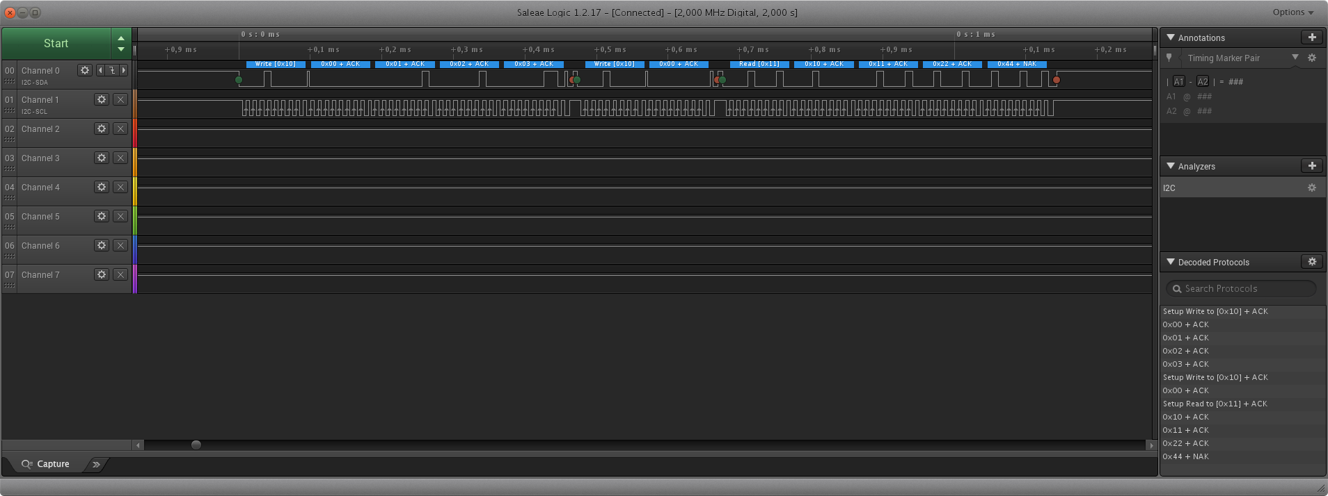
ich glaube ich hab's jetzt. Entweder ist die Appnote AN2824 fehlerhaft
oder ich habe sie falsch verstanden. Wenn ich mich strikt ans
Referenzmanual halte, klappt es nämlich.

Der letzte Code-Block zum Empfangen sieht jetzt so aus:
1 // Read some bytes (data)
2 SET_BIT ( I2C1 -> CR1 , I2C_CR1_ACK );
3 SET_BIT ( I2C1 -> CR1 , I2C_CR1_START ); // send START condition
4 while ( ! READ_BIT ( I2C1 -> SR1 , I2C_SR1_SB )); // wait until START has been generated
5 WRITE_REG ( I2C1 -> DR ,( 8 << 1 ) + 1 ); // send 7bit slave address 8 + read mode
6 while ( ! READ_BIT ( I2C1 -> SR1 , I2C_SR1_ADDR )); // wait until address has been sent
7 READ_REG ( I2C1 -> SR2 ); // clear ADDR
8 while ( ! READ_BIT ( I2C1 -> SR1 , I2C_SR1_RXNE )); // wait until a data byte has been received
9 buffer [ 0 ] = READ_REG ( I2C1 -> DR ); // read data
10 while ( ! READ_BIT ( I2C1 -> SR1 , I2C_SR1_RXNE )); // wait until a data byte has been received
11 ; // do not read data to initiate clock stretching
12 while ( ! READ_BIT ( I2C1 -> SR1 , I2C_SR1_BTF )); // wait until clock stretching begins
13 CLEAR_BIT ( I2C1 -> CR1 , I2C_CR1_ACK ); // prepare to send a NACK
14 buffer [ 1 ] = READ_REG ( I2C1 -> DR ); // read data
15 __disable_irq ();
16 SET_BIT ( I2C1 -> CR1 , I2C_CR1_STOP ); // prepare to send a STOP condition
17 buffer [ 2 ] = READ_REG ( I2C1 -> DR ); // read data
18 __enable_irq ();
19 while ( ! READ_BIT ( I2C1 -> SR1 , I2C_SR1_RXNE )); // wait until a data byte has been received
20 buffer [ 3 ] = READ_REG ( I2C1 -> DR ); // read data
21 while ( READ_BIT ( I2C1 -> SR1 , I2C_CR1_STOP )); // wait until STOP has been generated
http://www.st.com/content/ccc/resource/technical/document/application_note/5d/ae/a3/6f/08/69/4e/9b/CD00209826.pdf/files/CD00209826.pdf/jcr:content/translations/en.CD00209826.pdf

Ich denke, die Figure1 auf Seite 7 ist falsch, da fehlt "Read Data
N-2)".
von
Stefan F. (Gast)
27.04.2018 19:43
Vielen Danke für eure Hilfe (in dem anderen Thread bezüglich des NACK).
Ich habe noch eine Fehler entdeckt: Statt Repeat-Start hat kein Programm
Stop+Start gesendet. Das ist jetzt auch korrigiert.

Folgender Quelltext ist jetzt dabei heraus gekommen:

Initialisierung der I2C Schnittstelle:
1 /**
2 * Initialize the I²C interface.
3 * Note that the variable SystemCoreClock must be set before.
4 * The related I/O pins must be configured for alternate I/O open-drain AFTER this function.
5 *
6 * @param registerStruct May be either I2C1 or I2C2
7 * @param fastMode low=100kHz, high=400kHz
8 */
9 void i2c_init ( I2C_TypeDef * registerStruct , bool fastMode )
10 {
11 // Enable clock
12 if ( registerStruct == I2C1 )
13 {
14 SET_BIT ( RCC -> APB1ENR , RCC_APB1ENR_I2C1EN );
15 }
16 else if ( registerStruct == I2C2 )
17 {
18 SET_BIT ( RCC -> APB1ENR , RCC_APB1ENR_I2C2EN );
19 }
20 MODIFY_REG ( registerStruct -> CR2 , I2C_CR2_FREQ , SystemCoreClock / 1000000 ); // System clock in MHz
21 if ( fastMode )
22 {
23 MODIFY_REG ( registerStruct -> CCR , I2C_CCR_CCR , SystemCoreClock / 800000 ); // Clock pulse width 125ns+125ns
24 MODIFY_REG ( registerStruct -> TRISE , I2C_TRISE_TRISE , 3 ); // Maximum rise time 250ns (+1)
25 }
26 else
27 {
28 MODIFY_REG ( registerStruct -> CCR , I2C_CCR_CCR , SystemCoreClock / 200000 ); // Clock pulse width 500ns+500ns
29 MODIFY_REG ( registerStruct -> TRISE , I2C_TRISE_TRISE , 9 ); // Maximum rise time 100ns (+1)
30 }
31 SET_BIT ( registerStruct -> CR1 , I2C_CR1_PE ); // enable the peripheral
32 }
Senden und empfangen: 1 /**
2 * Perform an I²C transaction, which sends 0 or more data bytes, followed by receiving 0 or more data bytes.
3 *
4 * @param registerStruct May be either I2C1 or I2C2
5 * @param slave_addr 7bit slave_addr (will be shifted within this function)
6 * @param send_buffer Points to the buffer that contains the data bytes that shall be sent (may be 0 if not used)
7 * @param send_size Number of bytes to send
8 * @param receive_buffer Points to the buffer will be filled with the received bytes (may be 0 if ot used, may be the same as the send_buffer)
9 * @param receive_size Number of bytes to receive
10 * @return Number of received data bytes
11 */
12 unsigned int i2c_communicate ( I2C_TypeDef * registerStruct , uint8_t slave_addr , void * send_buffer , unsigned int send_size , void * receive_buffer , unsigned int receive_size )
13 {
14 unsigned int receive_count = 0 ;
15
16 // shift the 7bit address to the right position
17 slave_addr = slave_addr << 1 ;
18
19 // Send data
20 if ( send_size > 0 )
21 {
22 // Send START and slave address
23 SET_BIT ( registerStruct -> CR1 , I2C_CR1_START ); // send START condition
24 while ( ! READ_BIT ( registerStruct -> SR1 , I2C_SR1_SB )); // wait until START has been generated
25 WRITE_REG ( registerStruct -> DR , slave_addr ); // send slave address
26 while ( ! READ_BIT ( registerStruct -> SR1 , I2C_SR1_ADDR )) // wait until address has been sent
27 {
28 if ( READ_BIT ( registerStruct -> SR1 , I2C_SR1_AF ))
29 {
30 // did not receive ACK after address
31 goto error ;
32 }
33 }
34
35 READ_REG ( registerStruct -> SR2 ); // clear ADDR
36 while ( send_size > 0 )
37 {
38 WRITE_REG ( registerStruct -> DR , * (( uint8_t * ) send_buffer )); // send register no
39 while ( ! READ_BIT ( registerStruct -> SR1 , I2C_SR1_TXE )) // wait until Tx register is empty
40 {
41 if ( READ_BIT ( registerStruct -> SR1 , I2C_SR1_AF ))
42 {
43 // did not receive ACK after data byte
44 goto error ;
45 }
46 }
47 send_buffer ++ ;
48 send_size -- ;
49 }
50 while ( ! READ_BIT ( registerStruct -> SR1 , I2C_SR1_BTF )) // wait until last byte transfer has finished
51 {
52 if ( READ_BIT ( registerStruct -> SR1 , I2C_SR1_AF ))
53 {
54 // did not receive ACK after data byte
55 goto error ;
56 }
57 }
58 }
59
60 CLEAR_BIT ( registerStruct -> CR1 , I2C_CR1_POS ); // POS=0
61 SET_BIT ( registerStruct -> CR1 , I2C_CR1_ACK ); // acknowledge each byte
62
63 // Receive data
64 // The procedure includes workaround as described in AN2824
65 if ( receive_size > 0 )
66 {
67 // Send (RE-)START and slave address
68 SET_BIT ( registerStruct -> CR1 , I2C_CR1_START ); // send START condition
69 while ( ! READ_BIT ( registerStruct -> SR1 , I2C_SR1_SB )); // wait until START has been generated
70 WRITE_REG ( registerStruct -> DR , slave_addr + 1 ); // send slave address + read mode
71 while ( ! READ_BIT ( registerStruct -> SR1 , I2C_SR1_ADDR )) // wait until address has been sent
72 {
73 if ( READ_BIT ( registerStruct -> SR1 , I2C_SR1_AF ))
74 {
75 // did not receive ACK after address
76 goto error ;
77 }
78 }
79
80 if ( receive_size > 2 )
81 {
82 READ_REG ( registerStruct -> SR2 ); // clear ADDR
83 while ( receive_size > 3 )
84 {
85 while ( ! READ_BIT ( registerStruct -> SR1 , I2C_SR1_RXNE )); // wait until a data byte has been received
86 * (( uint8_t * ) receive_buffer ) = READ_REG ( registerStruct -> DR ); // read data
87 receive_size -- ;
88 receive_count ++ ;
89 receive_buffer ++ ;
90 }
91 while ( ! READ_BIT ( registerStruct -> SR1 , I2C_SR1_BTF )); // wait until 2 bytes are received
92 CLEAR_BIT ( registerStruct -> CR1 , I2C_CR1_ACK ); // prepare to send a NACK
93 * (( uint8_t * ) receive_buffer ) = READ_REG ( registerStruct -> DR ); // read data
94 receive_size -- ;
95 receive_count ++ ;
96 receive_buffer ++ ;
97 __disable_irq ();
98 {
99 SET_BIT ( registerStruct -> CR1 , I2C_CR1_STOP ); // prepare to send a STOP condition
100 * (( uint8_t * ) receive_buffer ) = READ_REG ( registerStruct -> DR ); // read data
101 receive_size -- ;
102 receive_count ++ ;
103 receive_buffer ++ ;
104 }
105 __enable_irq ();
106 }
107 else if ( receive_size == 2 )
108 {
109 SET_BIT ( registerStruct -> CR1 , I2C_CR1_POS ); // NACK shall be applied to the next byte, not the current byte
110 __disable_irq ();
111 {
112 READ_REG ( registerStruct -> SR2 ); // clear ADDR
113 CLEAR_BIT ( registerStruct -> CR1 , I2C_CR1_ACK ); // prepare to send a NACK
114 }
115 __enable_irq ();
116 while ( ! READ_BIT ( registerStruct -> SR1 , I2C_SR1_BTF )); // wait until 2 bytes are received
117 __disable_irq ();
118 {
119 SET_BIT ( registerStruct -> CR1 , I2C_CR1_STOP ); // prepare to send a STOP condition
120 * (( uint8_t * ) receive_buffer ) = READ_REG ( registerStruct -> DR ); // read data
121 receive_size -- ;
122 receive_count ++ ;
123 receive_buffer ++ ;
124 }
125 __enable_irq ();
126 }
127 else if ( receive_size == 1 )
128 {
129 CLEAR_BIT ( registerStruct -> CR1 , I2C_CR1_ACK ); // prepare to send a NACK
130 __disable_irq ();
131 {
132 READ_REG ( registerStruct -> SR2 ); // clear ADDR
133 SET_BIT ( registerStruct -> CR1 , I2C_CR1_STOP ); // prepare to send a STOP condition
134 }
135 __enable_irq ();
136 while ( ! READ_BIT ( registerStruct -> SR1 , I2C_SR1_RXNE )); // wait until a data byte has been received
137 }
138
139 * (( uint8_t * ) receive_buffer ) = READ_REG ( registerStruct -> DR ); // read the last data byte
140 receive_size -- ;
141 receive_count ++ ;
142 receive_buffer ++ ;
143 while ( READ_BIT ( registerStruct -> SR1 , I2C_CR1_STOP )); // wait until STOP has been generated
144 }
145
146 else if ( receive_size == 0 && send_size > 0 )
147 {
148 SET_BIT ( registerStruct -> CR1 , I2C_CR1_STOP ); // send STOP condition
149 while ( READ_BIT ( registerStruct -> CR1 , I2C_CR1_STOP )); // wait until STOP has been generated
150 }
151
152 return receive_count ;
153
154 error:
155 SET_BIT ( registerStruct -> CR1 , I2C_CR1_STOP ); // send STOP condition
156 while ( READ_BIT ( registerStruct -> CR1 , I2C_CR1_STOP )); // wait until STOP has been generated
157 CLEAR_BIT ( registerStruct -> CR1 , I2C_CR1_PE ); // restart the I2C interface clear all error flags
158 SET_BIT ( registerStruct -> CR1 , I2C_CR1_PE );
159 ITM_SendString ( "I2C bus error! \n " );
160 return receive_count ;
161 }
Beispiel Hauptprogramm: 1 int main ( void )
2 {
3 // Initialize system timer
4 SysTick_Config ( SystemCoreClock / 1000 );
5
6 // Enable Port B and alternate functions
7 SET_BIT ( RCC -> APB2ENR , RCC_APB2ENR_IOPBEN );
8 SET_BIT ( RCC -> APB2ENR , RCC_APB2ENR_AFIOEN );
9
10 // Initialize I2C1, no fast mode
11 i2c_init ( I2C1 , false );
12
13 // I2C1 uses remapped PB8=SCL, PB9=SDA, alternate function open-drain 2MHz
14 // Must be done after the I2C initialization otherwise the I/O pins would start with wrong logic level
15 SET_BIT ( AFIO -> MAPR , AFIO_MAPR_I2C1_REMAP );
16 MODIFY_REG ( GPIOB -> CRH , GPIO_CRH_CNF8 + GPIO_CRH_MODE8 , GPIO_CRH_CNF8_0 + GPIO_CRH_CNF8_1 + GPIO_CRH_MODE8_1 );
17 MODIFY_REG ( GPIOB -> CRH , GPIO_CRH_CNF9 + GPIO_CRH_MODE9 , GPIO_CRH_CNF9_0 + GPIO_CRH_CNF9_1 + GPIO_CRH_MODE9_1 );
18
19 // Send one byte with value 0, then receive 5 bytes
20 uint8_t buffer [ 20 ];
21 buffer [ 0 ] = 0 ;
22 int received = i2c_communicate ( I2C1 , 8 , buffer , 1 , buffer , 5 );
23 }
von
Regel Erkleerbehr (Gast)
27.04.2018 19:51
Stefanus F. schrieb:
> Folgender Quelltext ist jetzt dabei heraus gekommen:

... und du meinst das ist kein längerer Sourcecode?
von
Stefan F. (Gast)
27.04.2018 19:54
Für Hilfreiche Beiträge wäre ich dankbarer.
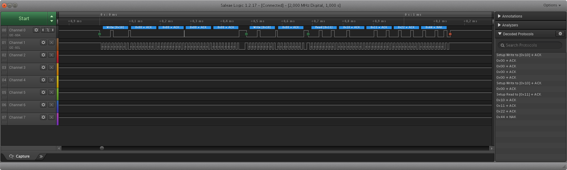
Wie dem auch sei, ich habe noch einen Screenshot vom Logic Analyzer für
die gleiche Sequenz gemacht, wie bei den vorherigen Screenshots:
1 uint8_t buffer [ 30 ];
2 buffer [ 0 ] = 0 ;
3 buffer [ 1 ] = 0 ;
4 buffer [ 2 ] = 0 ;
5 buffer [ 3 ] = 0 ;
6
7 // Send 3 Bytes starting at register 0
8 int received = i2c_communicate ( I2C1 , 8 , buffer , 4 , 0 , 0 );
9
10 // Receive 4 Bytes starting at register 0
11 received = i2c_communicate ( I2C1 , 8 , buffer , 1 , buffer , 4 );
Ich sehe im Bild keinen Fehler mehr.
von
Regel Erkleerbehr (Gast)
27.04.2018 19:57
Stefanus F. schrieb:
> Für Hilfreiche Beiträge wäre ich dankbarer.

Dieser Beitrag von mir ist für dein Posting-Verhalten
äusserst hilfreich, es sei denn du bist beratungsresistent
oder betonköpfig.
von
Stefan F. (Gast)
27.04.2018 20:52
Eine Korrektur für die init Funktion, die funktionierte nur bei 8Mhz
korrekt:
1 /**
2 * Initialize the I²C interface.
3 * The related I/O pins must be configured for alternate I/O open-drain AFTER this function.
4 *
5 * @param registerStruct May be either I2C1 or I2C2
6 * @param fastMode low=100kHz, high=400kHz
7 * @param apb1_clock clock frequency of APB1 peripherals
8 */
9 void i2c_init ( I2C_TypeDef * registerStruct , bool fastMode , long int apb1_clock )
10 {
11 // Enable clock
12 if ( registerStruct == I2C1 )
13 {
14 SET_BIT ( RCC -> APB1ENR , RCC_APB1ENR_I2C1EN );
15 }
16 else if ( registerStruct == I2C2 )
17 {
18 SET_BIT ( RCC -> APB1ENR , RCC_APB1ENR_I2C2EN );
19 }
20
21 // Configure timing
22 MODIFY_REG ( registerStruct -> CR2 , I2C_CR2_FREQ , apb1_clock / 1000000 );
23 if ( fastMode )
24 {
25 MODIFY_REG ( registerStruct -> CCR , I2C_CCR_CCR , apb1_clock / 800000 );
26 MODIFY_REG ( registerStruct -> TRISE , I2C_TRISE_TRISE , apb1_clock / 4000000 + 1 );
27 }
28 else
29 {
30 MODIFY_REG ( registerStruct -> CCR , I2C_CCR_CCR , apb1_clock / 200000 );
31 MODIFY_REG ( registerStruct -> TRISE , I2C_TRISE_TRISE , apb1_clock / 1000000 + 1 );
32 }
33
34 // enable the peripheral
35 SET_BIT ( registerStruct -> CR1 , I2C_CR1_PE );
36 }
Bitte melde dich an um einen Beitrag zu schreiben. Anmeldung ist kostenlos und dauert nur eine Minute.