Hallo zusammen,

ich bin gerade dabei, eine Platine zu routen.

Diese hat eine bidirektionale RS485 Schnittstelle, die vom Rest der
Schaltung isoliert ist. Alle Bauteile, die zur Schnittstelle gehören
(Max485 + Abblockkondensatoren + TVS Dioden, Bias Widerstände) verwenden
isolierte GND/+5V.

Die Schnittstelle zum uC muss natürlich ebenfalls isoliert sein, daher
habe ich zwei Optokoppler vom Typ HCPL0500 für RX und TX eingesetzt.

Meine Frage wäre nun, wie man die Ground/Power-Planes am besten zieht.

Es gibt zwei Planes ISO_GND und ISO_5V, die unter den
Schnittstellenkomponenten liegen.

Desweiteren gibt es zwei Planes GND und 5V, die so ziemlich überall
sonst auf der Platine verlaufen.

Gehe ich richtig in der Annahme, dass unter dem Optokoppler keine der
insgesamt 4 Planes liegen sollte?

Oder was wäre hier eine gute Praxis?

Freu  mich auf Vorschläge.

Dirk :)
@Mertens (Gast)

>Gehe ich richtig in der Annahme, dass unter dem Optokoppler keine der
>insgesamt 4 Planes liegen sollte?

Ja. Die isolierte Spannung mit ISO_GND und ISO_5V ist eine Insel, die
auch geometrisch vom Rest isoliert ist. Die Brücke zum Rest der
Schaltung machen eine Optokoppler bzw. der DC/DC Wandler.
Mertens schrieb:
> Gehe ich richtig in der Annahme, dass unter dem Optokoppler keine der
> insgesamt 4 Planes liegen sollte?

Üblicherweise soll unter den Optokopplern Isolierung liegen, damit sie
ihre Trennwirkung bzgl. der Isolationsspannung ausspielen können.
Irgenwelche, wie auch immer gearteten, Leiterflächen sind da
kontraproduktiv, weil sie die Isolationsabstände/Kriechstrecken
verringern.

In welchem Umfang du bei deinem Design die Isolationswirkung brauchst,
weisst du am besten. Geht es bei deinen zu übertragenden Signalen um MBd
oder kBd?
Ahoi und Danke für die Hinweise.

Das deckt sich auch mit meinem Verständnis.
Die Datenrate der seriellen Verbindung ist 19.2 kBd.
Selbst ein schlechtes Design sollte hier noch den Test bestehen, aber
man hat ja auch persönliche Ansprüche ;)

Ich werde zwischen der Schnittstelle und dem Rest der Platine die
Optokoppler und den isolierenden DC/DC Wandler platzieren.
Das ist dann auch optisch schön struktiert. So mag ich das ;)

LG, Dirk
Angehängte Dateien:
-

3.3.4-1.jpg
130 KB
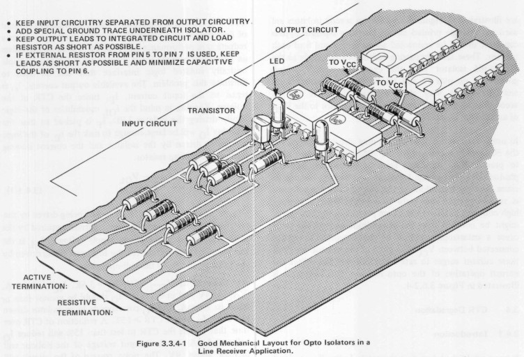
Mertens schrieb:
> Gehe ich richtig in der Annahme, dass unter dem Optokoppler keine der
> insgesamt 4 Planes liegen sollte?

Normalerweise wird das so gemacht.

Aber wenn dir Störunempfindlichkeit wichtiger als Isolierung ist,
empfiehlt HP eine Masseleitung unter dem Chip:
> 3.3.4 Layout Considerations for Optically Coupled Isolators
>
> Optically coupled isolators have excellent common mode
> rejection characteristics. However, for optimum common
> mode rejection, special considerations should be given to
> the circuit layout. Stray capacitance between the input
> circuit and the output circuit should be minimized. This
> can be done by physically separating all input and output
> circuitry on the circuit board. For line receiver applications,
> the shielded cable should also be dressed properly to
> minimize stray capacitance. Since the base of the output
> transistor is especially susceptible to common mode
> transients, a special ground trace under the isolator can
> serve as a shield. To further minimize capacitive coupling
> into the base, pin 7 can be clipped off at the side of the
> package. A simpler approach in an application requiring
> more than one isolator is to use dual packages, because the
> base is unconnected.
>
> Circuit layout can also effect propagation delays through
> the optically coupled isolators. Since most opto isolators
> have an open collector output, excessive shunt capacitance
> on pin 6 can limit rise and fall times of the isolator. For this
> reason, the logic gate being driven by the isolator should be
> as close to the isolator as possible and the pullup resistor
> mounted in close proximity to the isolator.
(HP Optoelectronics Applications Manual,
https://archive.org/details/HewlettPackard-OptoelectronicsApplicationsManualOCR)
Bitte melde dich an um einen Beitrag zu schreiben. Anmeldung ist kostenlos und dauert nur eine Minute.
Bestehender Account
Schon ein Account bei Google/GoogleMail? Keine Anmeldung erforderlich!
Mit Google-Account einloggen
Mit Google-Account einloggen
Noch kein Account? Hier anmelden.