Hallo zusammen,
ich habe ein Beispiel auf der fogenden Seite gefunden:
http://forum.arduino.cc/index.php?topic=420674.0
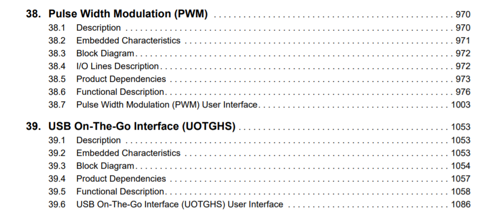
Dieses habe ich im AtmelStudio getestet und ein PWM an Pin PC7 messen
können.
Allerdings erhalte ich nicht eine Frequenz von 1 Hz, sondern von 2,7 Hz.
Habt ihr eine Idee, woran das liegt. Bei diesem Controller kann ich
unter Tools > Device Programming > Fuse Bits ja nicht die Taktquelle
verändern (wie beim Atmega2560).
1 |
|
2 | // PWM Set-up on pin PC7 (Arduino Pin 39): see Datasheet chap. 38.5.1
|
3 | // Select Instance=PWM; Signal=PWMH2 (channel 2); I/O Line=PC7 (P7, Arduino pine 39, see pinout diagram) ; Peripheral=B
|
4 |
|
5 | PMC->PMC_PCER1 |= PMC_PCER1_PID36; // PWM on
|
6 |
|
7 | REG_PIOC_ABSR |= PIO_ABSR_P7; // Set PWM pin perhipheral type B
|
8 |
|
9 | REG_PIOC_PDR |= PIO_PDR_P7; // Set PWM pin to an output
|
10 |
|
11 | REG_PWM_ENA = PWM_ENA_CHID2; // Enable the PWM channel 2 (see datasheet page 973)
|
12 |
|
13 | REG_PWM_CLK = PWM_CLK_PREA(0) | PWM_CLK_DIVA(42); // Set the PWM clock rate to 2MHz (84MHz/42). Adjust DIVA for the resolution you are looking for
|
14 |
|
15 | REG_PWM_CMR2 = PWM_CMR_CALG |PWM_CMR_CPRE_CLKA; // The period is left aligned, clock source as CLKA on channel 2
|
16 |
|
17 | REG_PWM_CPRD2 = 1000000; // Channel 2 : Set the PWM frequency 2MHz/(2 * CPRD) = F ; 1< CPRD < 2exp24 -1 ; here CPRD = 10 exp 6
|
18 |
|
19 | REG_PWM_CDTY2 = 200000; // Channel 2: Set the PWM duty cycle to x%= (CDTY/ CPRD) * 100 % , CDTY = 2 * 10 exp 5
|
20 |
|
21 | // Alternatively, you can use this format : PWM->PWM_CH_NUM[2].PWM_CPRD = 1000000 ;
|
22 | // In this example, Frequency is 1 HZ with a DT of 20% so you can see it with an LED attached to pin 39 with a resistor
|
23 |
|
24 | }
|