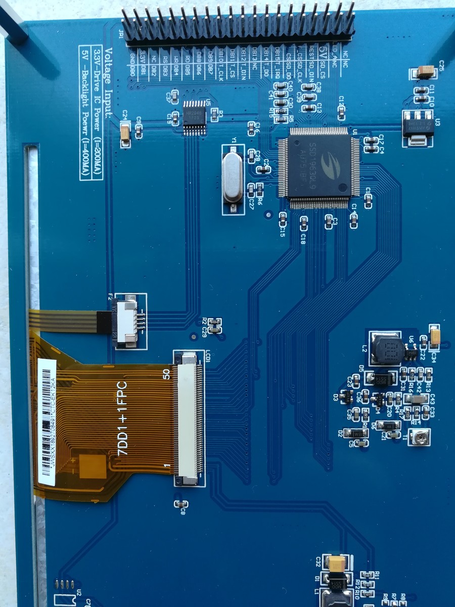
Hallo
hat jemand die Initialisierungsroutine in C für das Disp. (siehe Bild)?
Für das 5 Zoll habe ich sie. Fkt. aber nicht für 7 Zoll.
Wir könnten tauschen?

VG Walter
Angehängte Dateien:
-

IMG_20181117_102122.jpg
240 KB
Walter L. schrieb:
> hat jemand die Initialisierungsroutine in C für das Disp.

Für das Display hab ich sowas, zu benutzen auf einem LPC4088 mit dessen
Display-Peripherie-Core. Dazu ein niedlicher externer SDRAM von 32 Bit
Datenbreite und das Ganze ist fertig. Ich hab sowas mEn vor ein paar
Jahren hier schon mal gepostet.

Aber was den Displaycontroller betrifft, der auf der gezeigten LP sitzt,
da solltest du ganz eingach dessen Manual lesen.

W.S.
Hier die Lösung.


//
////////////////////////////////////////////////////////////////////////
////////////
// Function: TFT_WR_REG -> CMD TFT_WR_DATA -> daten für das CMD
// Aufruf
// Input:
// Output:
//
////////////////////////////////////////////////////////////////////////
////////////
void INIT_TFT_V1(void)
{
    TFT_CS_1;            //
    TFT_RESET_1_disable; //
    delayms(5);          //
    TFT_RESET_0_enable;  //
    delayms(5);          //
    TFT_RESET_1_disable; //
    TFT_WR_1;       //   1 die ruhestellung ist und mit der neg Flanke
geschrieben wird
    TFT_CS_0;
    delayms(5);

    // Set the PLL S74
        TFT_WR_REG(0x00E2);  //  PLL multiplier, set PLL clock to 100M
diese reihenfolge ist richtig S74
        TFT_WR_DATA(0x001d); // M[7:0] : Multiplier (M) of PLL. (POR =
00101101) =0x2D
        TFT_WR_DATA(0x0002); // N[3:0] : Divider (N) of PLL. (POR =
0011)
        TFT_WR_DATA(0x0004); // C[2] : = 1; Effectuate MN value (POR =
0) 1 Effectuate the multiplier and divider value
    // Start the PLL. S73
        TFT_WR_REG(0x00E0);  // Command PLL enable
        TFT_WR_DATA(0x0001); // PLL enable
        delayms(1);          // im datenbaaltt 100 usek
        TFT_WR_REG(0x00E0);
        TFT_WR_DATA(0x0003);
        delayms(5);
    // The SSD1963 performs a software reset. All the configuration
register will be reset except command 0xE0 to 0xE5. S24
        TFT_WR_REG(0x0001);  // software reset
        delayms(6);          //The host processor must wait 5ms before
sending any new commands to a SSD1963 following this command.
    // https://www.youtube.com/watch?v=VZ9jTYRINtc Set the LSHIFT (pixel
clock) frequency
        TFT_WR_REG(0x00E6);  //PLL setting for PCLK, depends on
resolution
        TFT_WR_DATA(0x0004);
        TFT_WR_DATA(0x0070);
        TFT_WR_DATA(0x00a9);

// START !!! der TEXT unter dem VIDEO !!!
https://www.youtube.com/watch?v=7Da4mTISFeI
    TFT_WR_REG(0x000B); //SET SCAN MODE
    TFT_WR_DATA(0x0000); //SET TFT MODE top to bottom, left to right
normal etc

    TFT_WR_REG(0x000A);
    TFT_WR_DATA(0x001C); //Power Mode

    TFT_WR_REG(0x003A); //SET Pixel Format
    TFT_WR_DATA(0x0050); //16 bit pixel
    // TFT_WR_DATA(0x0060); //18 bit pixel
    // TFT_WR_DATA(0x0070); //24 bit pixel

    TFT_WR_REG(0x00F0); // Set Pixel Data Interface
    TFT_WR_DATA(0x0003); // 16-bit (565 format)

    TFT_WR_REG(0x00E2);
    TFT_WR_DATA(60); //35 PLLclk = REFclk * 36 (360MHz)
    TFT_WR_DATA(5); // SYSclk = PLLclk / 3 (120MHz)
    TFT_WR_DATA(0x0054); // validate M and N dec 84

    TFT_WR_REG(0x00e0);
    TFT_WR_DATA(0x0001); // START PLL
    delayms(2); // Wait 100us to let the PLL stable

    TFT_WR_REG(0x00e0);
    TFT_WR_DATA(0x0003); // LOCK PLL

    TFT_WR_REG(0x00B0); //SET LCD MODE SIZE !!
    TFT_WR_DATA(0x0019); //19 TFT panel data width - Enable FRC or
dithering for color depth enhancement
    TFT_WR_DATA(0x0020); //SET TFT MODE & hsync+Vsync+DEN MODE 20 or 00
    TFT_WR_DATA(0x0003); //SET horizontal size=800+1 HightByte !!
    TFT_WR_DATA(0x0021); //SET horizontal size=800+1 LowByte
    TFT_WR_DATA(0x0001); //SET vertical size=480+1 HightByte
    TFT_WR_DATA(0x00E1); //SET vertical size=480+1 LowByte
    TFT_WR_DATA(0x0000); //Even line RGB sequence / Odd line RGB
sequence RGB

    TFT_WR_REG(0x00e6); // pixel clock frequency
    TFT_WR_DATA(0x0004); // LCD_FPR = 290985 = 33.300 Mhz Result for 7"
Display
    TFT_WR_DATA(0x0070);
    TFT_WR_DATA(0x00A9);

    TFT_WR_REG(0x00B4);     // Set Horizontal Period (Front Porch)
    TFT_WR_DATA(0x0003); // High byte of horizontal total period
(display + non-display)
    TFT_WR_DATA(0x005E); // Low byte of the horizontal total period
(display + non-display)
    TFT_WR_DATA(0x0000); //High byte of the non-display period between
the start of the horizontal sync (LLINE) signal and the first display
data.
    TFT_WR_DATA(0x0046); //** // 46 Low byte of the non-display period
between the start of the horizontal sync (LLINE) signal and the first
display data
    TFT_WR_DATA(0x0009); //Set the vertical sync pulse width
    TFT_WR_DATA(0x0000); //SET Hsync pulse start position //00
    TFT_WR_DATA(0x0000);
    TFT_WR_DATA(0x0000); //SET Hsync pulse subpixel start position // **
too small will give you half a PICTURE !!

    TFT_WR_REG(0x00B6); //Set Vertical Period
    TFT_WR_DATA(0x0001); //01 High byte of the vertical total (display +
non-display) period in lines was 1F5
    TFT_WR_DATA(0x00FE); //F4 Low byte F5 INCREASES SYNC TIME AND BACK
PORCH 1D WAS 00 OR f5
    TFT_WR_DATA(0x0000); // 00
    TFT_WR_DATA(0x000C); //0C =12 The non-display period in lines
between the start of the frame and the first display data in line.
    TFT_WR_DATA(0x0000); //Set the vertical sync pulse width (LFRAME) in
lines.
    TFT_WR_DATA(0x0000); //SET Vsync pulse start position
    TFT_WR_DATA(0x0000); //Flip below


    TFT_WR_REG(0x0036); //
    TFT_WR_DATA(8); //
// ENDE !!! der TEXT unter dem VIDEO !!!
https://www.youtube.com/watch?v=7Da4mTISFeI

    TFT_WR_REG(0x0029); //display on

    TFT_WR_REG(0x00BE); //set PWM for B/L
    TFT_WR_DATA(0x0006);
    TFT_WR_DATA(0x00f0);
    TFT_WR_DATA(0x0001);
    TFT_WR_DATA(0x00f0);
    TFT_WR_DATA(0x0000);
    TFT_WR_DATA(0x0000);

    TFT_WR_REG(0x00d0);
    TFT_WR_DATA(0x000d);

    //----------LCD RESET---GPIO0-------------------//
    TFT_WR_REG(0x00B8);
    TFT_WR_DATA(0x0000);    //GPIO3_input, GPIO[2:0]_output
    TFT_WR_DATA(0x0001);    //GPIO0 normal

    TFT_WR_REG(0x00BA);
    TFT_WR_DATA(0x0000);
    TFT_CS_1;

}
Bitte melde dich an um einen Beitrag zu schreiben. Anmeldung ist kostenlos und dauert nur eine Minute.
Bestehender Account
Schon ein Account bei Google/GoogleMail? Keine Anmeldung erforderlich!
Mit Google-Account einloggen
Mit Google-Account einloggen
Noch kein Account? Hier anmelden.