Hallo zusammen, ich arbeite schon seit einiger Zeit an einem Projekt und
komme nun an dieser Stelle garnicht weiter... Ich habe schon ein paar
Posts in anderen Foren (englisch sprachig) gemacht, jedoch bei diesen
kaum Beachtung geschenkt bekommen. Meinen originalen Post seht ihr unter
diesem Vermerk auf englisch, ich hoffe ihr habt kein Problem damit. Ich
wäre euch so dankbar wenn ihr mir weiter helfen könntet und freue mich
auf jede Antwort! Hier der Post:

PS. Angehängte Datei nicht beachten, da ist was schief gelaufen :/
--------------------------------------

Hello everyone,

so I've been working on this project for a while now and stumbled upon a
problem which I haven't been able to solve so far. For this project I'm
using an ESP8266 NodeMCU 1.0 with industrial buttons (see link below)
connected to the PCF8574 port expander (I also integrated ws2812 smd's
into the buttons). For the buttons I use a modified header file
(input_pcf.h) which was initially written by a friend of mine and for
the ws2812 I am also using a header file (neo.h) written by the same
friend (both of them are working fine). As for the port expander, I use
the PCF8574 library written by xreef on github
https://github.com/xreef/PCF8574_library . To sum everything up, I
connected the buttons to (GND and) the PCF8574, which is connected to
the Microcontroller via I2C. The data bus of the smd's are also
connected to the ESP.

industrial buttons:
https://de.aliexpress.com/item/KEINE-NC-START-STOP-DPST-LED-Momentary-Drucktastenschalter-AC-220-V-F-r-Starter-Sch-tz/32841013279.html?spm=a2g0s.11045068.rcmd404.3.7af356a4BSADBP&pvid=39e487c7-cbee-4b92-91dc-703921392acb&gps-id=detail404&scm=1007.16891.96945.0&scm-url=1007.16891.96945.0&scm_id=1007.16891.96945.0

(Almost) everything has been working fine so far, until I modified the
input.h file and connected the buttons to the port expander. You
initialize the input object with a pin, which is connected to a button.
You can connect the industrial button two ways: on the closing side and
on the opening side, I am using the opening side against GND. As I
cannot just initialize the input object with a pin from the port
expander, I just modified the input.h to input_pcf.h where I also have
to pass a reference of the PCF8574 object to it, so I can directly read
the pin state in my input_pcf.h. Unfortunately, this is not working at
all. The button presses are not detected at all and nothing is reacting
to it. Now I am trying to resolve the problem...

...did I do something wrong when passing the object by reference?
...is there a fallacy in my logic to it?

I have checked all connections many times, so I am pretty sure the
connections are fine. When examining the button press with the esp,
everything is working fine, and the smd's light up as intended. I tested
the port expander as well with a simple code where I light up an LED and
there were no problems with it. I hope some of you could help me to
solve this problem! The code of all relevant files used are below. Thank
you in advance!

NOTE: I know the code needs some refactoring and the names of some
functions might be somewhat ambiguous (like setup() or loop() in neo.h).
Please try to ignore these issues when answering

simplePCFInputTest.ino
I think that nobody was able to help ypu because you did not provide the
schematics.
> Unfortunately, this is not working at> all. The button presses are not detected
This is no real proper problem description.
1) You should reduce your program to the smalles possible version which
still has the problem.
2) You should measure the operating voltage of the microcontroller as
well as the voltages on the related I/O pins.
3) Since you have issues to read data from the PCF8574, check if you can
successfully use the oppsite direction (e.g. switch LEDs on and off).
4) Since you are using I²C communication, it is very important to
measure the voltate on the I²C bus before and during the error. I would
also high recommend to use an logic analysator (costs only 10€) to find
out what's going on with the two signal lines.
Hello,
Stefanus F. schrieb:> I think that nobody was able to help ypu because you did not> provide the> schematics.>>> Unfortunately, this is not working at>> all. The button presses are not detected>> This is no real proper problem description.>> 1) You should reduce your program to the smalles possible version which> still has the problem.>> 2) You should measure the operating voltage of the microcontroller as> well as the voltages on the related I/O pins.>> 3) Since you have issues to read data from the PCF8574, check if you can> successfully use the oppsite direction (e.g. switch LEDs on and off).>> 4) Since you are using I²C communication, it is very important to> measure the voltate on the I²C bus before and during the error. I would> also high recommend to use an logic analysator (costs only 10€) to find> out what's going on with the two signal lines.
thank you very much for your suggestions Stefanus. It has been a while
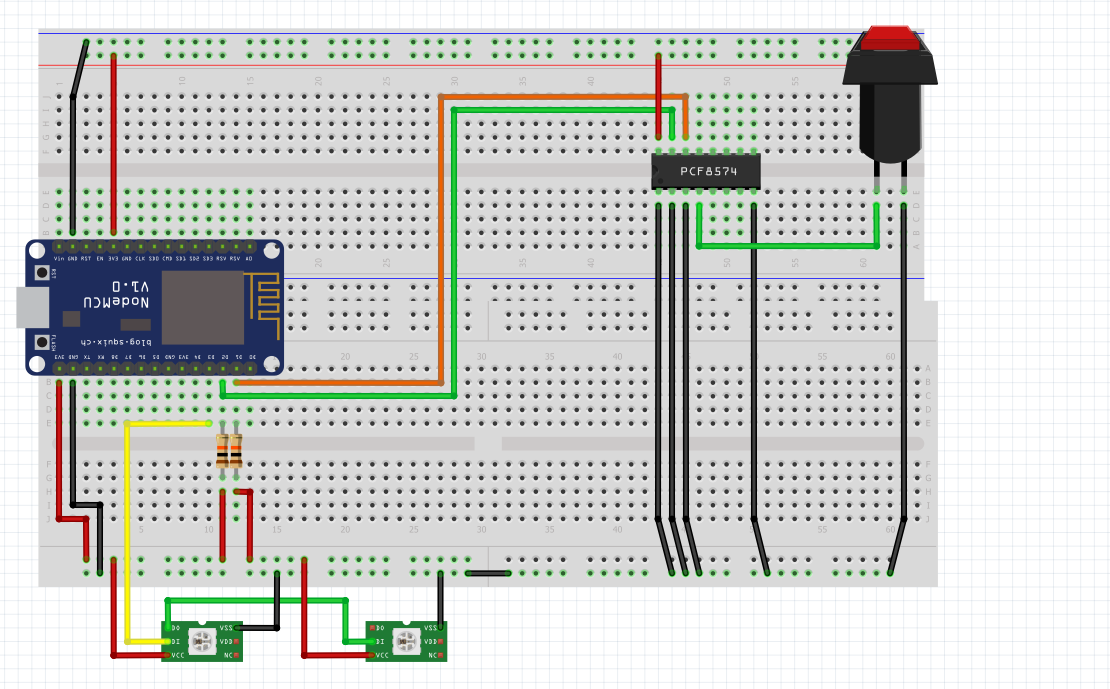
since I started working on my project again. I have just created the
schematics of my project (see attachments). Also, I am going to measure
the voltage on each pin today and post an update later.
Best regards!
Stefanus F. schrieb:> 3) Since you have issues to read data from the PCF8574, check if you can> successfully use the oppsite direction (e.g. switch LEDs on and off).
I have already tried this out a few days prior to my post and it worked
fine, thats why I got so confused. I am pretty sure there is some issue
with passing the PCF-Object as reference... I will post an update pretty
soon!
Best regards!
Ed S. schrieb:> I have just created the schematics of my project (see attachments).
Pse check your attachment. You appended a fancy picture but not the
schematic for your circuit.
Hello,
W.A. schrieb:> Pse check your attachment. You appended a fancy picture but not the> schematic for your circuit.
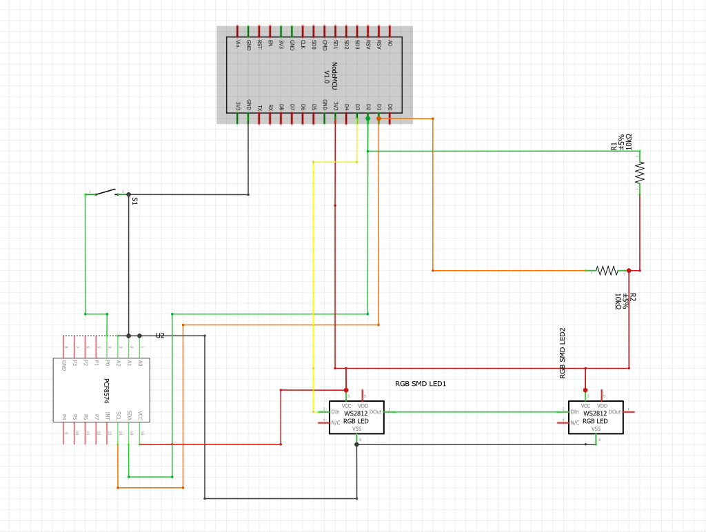
thanks for clearing this out! I hope the picture in this attachment is
sufficient enough. I will also provide you guys with the fritzing file
if needed.
Best regards.
I see two possible issues.
10kΩ ist too much for the I²C Pull-Up resistors. Better use 2,2kΩ or
1,8kΩ.
The WS2812LED might require 5V power supply and you should put a
resistor (220 - 470Ω) in the signal line. I'm not sure why this is
needed but it was suggested very often by other people.
Stefanus F. schrieb:> 10kΩ ist too much for the I²C Pull-Up resistors. Better use 2,2kΩ or> 1,8kΩ.
Ok, I will try it out.
Stefanus F. schrieb:> The WS2812LED might require 5V power supply and you should put a> resistor (220 - 470Ω) in the signal line. I'm not sure why this is> needed but it was suggested very often by other people.
I have read these suggestions as well. Another thread suggested (can't
find it right now) that you can operate WS2812 smds on 3.3 V if you use
3.3V for your data lines as well. Using this voltage hasn't caused me
any trouble so far (tried it out in prior projects or tests). That's why
I omitted the resistor in my circuit.
Best regards.
Ed S. schrieb:> simplePCFInputTestSCHEMATICS.PNG
You should provide a power supply for the LEDs (VDD on WS2812).
Filters on VCC line are missing at WS2812 (100nF capacitor and 150Ω
serial resistor, cf. datasheet "Typical application circuit").
Regards
Hello everyone,
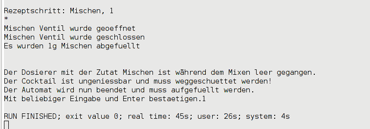
so I have had some time to measure the voltage on all (necessary) pins.
And basically everything seems to work properly, only the P0 pin of the
PCF module doesn't seem to react (although I set the pin HIGH from the
very beginning). You can see my measurements below.
Without any button presses (standby):
//ESP8266
ESP(D1) = 3.24 V //I2C SCL line
ESP(D2) = 3,24 V //I2C SDA line
ESP(D3) = 0 V //Data line of WS2812 (WS1) chip
//PCF8574
PCF(SCL) = 3,25 V
PCF(SDA) = 3,24 V
PCF(VCC) = 3,29 V
PCF(A0) = 0 V //address pins
PCF(A1) = 0 V
PCF(A2) = 0 V
PCF(P0) = 0 V //?! should be high
//WS2812
WS1(VCC) = 3,29 V //first WS2812 chip
WS1(DIN) = 0 V
WS1(DOUT) = 0 V
WS2(VCC) = 3,28 V //second WS2812 chip
WS2(DIN) = 0 V
//Button
S1(IN) = 0 V //Connected to P0 pin of PCF
S1(OUT) = 0 V //Connected to GND
When the button is pressed:
//PCF8574
PCF(P0) = 0 V //...
//Button
S1(IN) = 0 V
S1(OUT) = 0 V
Everything else just behaved the same.
I have also done another Test where the button press is detected by the
ESP8266 and the P0 pin of the PCF module just sets an LED high or low
accordingly. The code is almost the same (see below), except I don't
pass any references of the PCF Object to another class. Everything works
as intended in this test. The LED as well as the WS2812 SMDs light up
when the button is pressed once, and get off when the button is pressed
a second time (just tell me if you need the schematics of the second
test below).
simplePCFTest.ino
PS: I use a different header file for the button in this one called
"input.h" which works the same as "input_pcf.h" but only takes a pin as
an argument.

Best regards!
Stefanus F. schrieb:> 10kΩ ist too much for the I²C Pull-Up resistors. Better use 2,2kΩ or> 1,8kΩ.
Oh, and I switched to 3,3k resistors (I only had these or higher :/) but
nothing really changed.
W.A. schrieb:> You should provide a power supply for the LEDs (VDD on WS2812).
Is that really necessary? The SMDs seem to work fine even without the
VDD power supply (light up in all colors) and I have already soldered
and integrated them into the industrial buttons :d
W.A. schrieb:> Filters on VCC line are missing at WS2812 (100nF capacitor and 150Ω> serial resistor, cf. datasheet "Typical application circuit").
Ok, I will connect them to the circuit and post an update (most likely
tomorrow).
Best regards
Ed S. schrieb:> Oh, and I switched to 3,3k resistors (I only had these or higher :/) but> nothing really changed.
Keep them anyway to improve stability. When you attach an oscilloskope
then you will see that 10kΩ are very sensitive to the RF signal of the
WiFi antenna and the logic signal changes very slowly from LOW to HIGH.
The I/O Pin on the PCF should be high. It seems that the chip is not
initialized properly - maybe due to broken communication. Can you check
the communication with a logic anaylzer (Saleae or similar)?
Stefanus F. schrieb:> The I/O Pin on the PCF should be high. It seems that the chip is not> initialized properly - maybe due to broken communication. Can you check> the communication with a logic anaylzer (Saleae or similar)?
Hello,
well, I have to buy one which will take a couple of days. I'm not sure
if it will help me in this particular scenario but I will give it a try!
Best regards!
First of all your call by reference is fine. However you are facing
several problems here.

Let's start with the library you are using. Have a look at the source
code and you'll see it is pretending to implement all the functions
you'd typically expect from Arduino's digitalWrite() and pinMode()
methods rather than actually implementing them in the same way.

For example the begin() method of the lib initializes the Wire library
for you so calling
1
pcf.digitalWrite(btn,HIGH)
before calling
1
pcf.begin()
will issue an I²C transmission to an uninitialized Wire object. Not the
best idea really and more likely to crash your µC than anything else.

The PCF library also inhibits any write commands to your output pins as
soon as you declare them as inputs. That's why you don't see any HIGH
output on pin 0.
1
pcf.pinMode(btn,INPUT);
2
pcf.digitalWrite(btn,HIGH);
3
pcf.begin();
This can't work as stated above because the digitalWrite has no effect
on the pin. You'd rather need to do the following:
1
pcf.begin();
2
pcf.pinMode(btn,OUTPUT);
3
pcf.digitalWrite(btn,HIGH);
4
pcf.pinMode(btn,INPUT);
This is very counter intuitive and a clear sign to maybe use another
library ;)

The second thing you have to consider is timing. You can't just poll the
I²C bus within your main loop because you will run into timing issues
and effectively block the bus and receive garbage data.
Have a delay between each call to pcf.digitalRead() or
pcf.digitalWrite()
of at least 10ms. This becomes very clear when you look at your Update()
method in input_pcf.h
Worst case: every line of your if clause is executed which results in 3
consecutive I²C requests without any delay between them for the bus to
process the requests. You will need to completely rewrite that part
using additional timers to compensate for this.
I haven't logged in for a while now and forgot to reply to the last
response. Sorry for that.

First of all I wanted to thank all of you for trying to help, especially
Günther S. who solved my problem with his response! I basically switched
to another pcf-library and solved my timing issues regarding the I2C
bus. So, thank you very much Günther S. for taking the time to help ;)

I might post an update very soon to the project.