Hallo,

es wird hier erklärt:

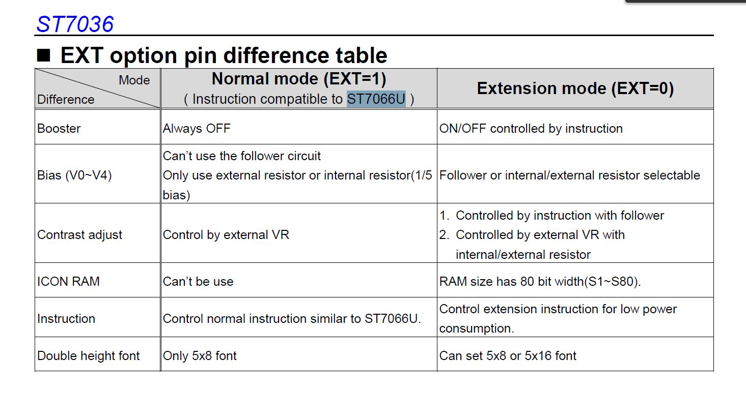
Controller InformationBuilt-in ST7036icontroller.Please
downloadspecificationathttp://www.newhavendisplay.com/app_notes/ST7036.pdf

Table 5

Relationship between CGRAM Addresses, Character Codes (DDRAM) and
Character patterns (CGRAM Data) Notes:  1. Character code bits 0 to 2
correspond to CGRAM address bits 3 to 5 (3 bits: 8 types). 2. CGRAM
address bits 0 to 2 designate the character pattern line position. The
8th line is the cursor position and its display is formed by a logical
OR with the cursor. Maintain the 8th line data, corresponding to the
cursor display position, at 0 as the cursor display. If the 8th line
data is 1, 1 bits will light up the 8th line regardless of the cursor
presence. 3. Character pattern row positions correspond to CGRAM data
bits 0 to 4 (bit 4 being at the left). 4. As shown Table 5, CGRAM
character patterns are selected when character code bits 4 to 7 are all
0. However, since character code bit 3 has no effect, the T display
example above can be selected by either character code 00H or 08H. 5.
“1” for CGRAM data corresponds to display selection and “0” to
non-selection,“-“  Indicates no effect. 6. Different OPR1/2 ITO option
can select different CGRAM size.

siehe auch Seite 33.

Icons kann man auch definieren.

mfG