Guten Tag,

Ich habe ein MPU6050 an ein Arduino Pro Micro gestöpselt mit Interupt.
Test Programm von i2cdevlib hochgeladen mit der DMP V6.12 Version.
Serial Monitor zeigt alles super an nur nach einer kurzen unbestimmte
Zeit erlischt die LED auf dem Board und die Verbindung ist weg. USB raus
und wieder rein und es funktioniert wieder nur eine kurze Zeit.
geschätzt unter einer Minute.

Weis jemand Rat?

mfg Erik
Um welches Boards geht es und was zeigt dessen LED an? Welches Programm
löst den Fehler aus? Welcher Teil dieses Programms ist ausschlaggebend?
Ein Schaltplan und ein Foto vom Aufbau wäre nicht schlecht.
Ich schicke einfach mal das ganze Programm. Die Mouse.move() hier bitte
ignorieren, es passiert auch ohne Mouse library.
Es geht um ein Arduino Pro Micro Board. Beim Uploaden muss man den als
Leonardo auswählen. Den Interupt Pin musste ich versetzen auf die 6
wegen der beiden SLC und SDA.
1 | // I2C device class (I2Cdev) demonstration Arduino sketch for MPU6050 class using DMP (MotionApps v6.12)
|
2 | // 6/21/2012 by Jeff Rowberg <jeff@rowberg.net>
|
3 | // Updates should (hopefully) always be available at https://github.com/jrowberg/i2cdevlib
|
4 | //
|
5 | // Changelog:
|
6 | // 2019-07-10 - Uses the new version of the DMP Firmware V6.12
|
7 | // - Note: I believe the Teapot demo is broken with this versin as
|
8 | // - the fifo buffer structure has changed
|
9 | // 2016-04-18 - Eliminated a potential infinite loop
|
10 | // 2013-05-08 - added seamless Fastwire support
|
11 | // - added note about gyro calibration
|
12 | // 2012-06-21 - added note about Arduino 1.0.1 + Leonardo compatibility error
|
13 | // 2012-06-20 - improved FIFO overflow handling and simplified read process
|
14 | // 2012-06-19 - completely rearranged DMP initialization code and simplification
|
15 | // 2012-06-13 - pull gyro and accel data from FIFO packet instead of reading directly
|
16 | // 2012-06-09 - fix broken FIFO read sequence and change interrupt detection to RISING
|
17 | // 2012-06-05 - add gravity-compensated initial reference frame acceleration output
|
18 | // - add 3D math helper file to DMP6 example sketch
|
19 | // - add Euler output and Yaw/Pitch/Roll output formats
|
20 | // 2012-06-04 - remove accel offset clearing for better results (thanks Sungon Lee)
|
21 | // 2012-06-01 - fixed gyro sensitivity to be 2000 deg/sec instead of 250
|
22 | // 2012-05-30 - basic DMP initialization working
|
23 | |
24 | /* ============================================
|
25 | I2Cdev device library code is placed under the MIT license
|
26 | Copyright (c) 2012 Jeff Rowberg
|
27 | |
28 | Permission is hereby granted, free of charge, to any person obtaining a copy
|
29 | of this software and associated documentation files (the "Software"), to deal
|
30 | in the Software without restriction, including without limitation the rights
|
31 | to use, copy, modify, merge, publish, distribute, sublicense, and/or sell
|
32 | copies of the Software, and to permit persons to whom the Software is
|
33 | furnished to do so, subject to the following conditions:
|
34 | |
35 | The above copyright notice and this permission notice shall be included in
|
36 | all copies or substantial portions of the Software.
|
37 | |
38 | THE SOFTWARE IS PROVIDED "AS IS", WITHOUT WARRANTY OF ANY KIND, EXPRESS OR
|
39 | IMPLIED, INCLUDING BUT NOT LIMITED TO THE WARRANTIES OF MERCHANTABILITY,
|
40 | FITNESS FOR A PARTICULAR PURPOSE AND NONINFRINGEMENT. IN NO EVENT SHALL THE
|
41 | AUTHORS OR COPYRIGHT HOLDERS BE LIABLE FOR ANY CLAIM, DAMAGES OR OTHER
|
42 | LIABILITY, WHETHER IN AN ACTION OF CONTRACT, TORT OR OTHERWISE, ARISING FROM,
|
43 | OUT OF OR IN CONNECTION WITH THE SOFTWARE OR THE USE OR OTHER DEALINGS IN
|
44 | THE SOFTWARE.
|
45 | ===============================================
|
46 | */
|
47 | |
48 | // I2Cdev and MPU6050 must be installed as libraries, or else the .cpp/.h files
|
49 | // for both classes must be in the include path of your project
|
50 | #include "I2Cdev.h" |
51 | |
52 | #include "MPU6050_6Axis_MotionApps_V6_12.h" |
53 | //#include "MPU6050.h" // not necessary if using MotionApps include file
|
54 | |
55 | // Arduino Wire library is required if I2Cdev I2CDEV_ARDUINO_WIRE implementation
|
56 | // is used in I2Cdev.h
|
57 | #if I2CDEV_IMPLEMENTATION == I2CDEV_ARDUINO_WIRE
|
58 | #include "Wire.h" |
59 | #endif
|
60 | |
61 | // class default I2C address is 0x68
|
62 | // specific I2C addresses may be passed as a parameter here
|
63 | // AD0 low = 0x68 (default for SparkFun breakout and InvenSense evaluation board)
|
64 | // AD0 high = 0x69
|
65 | MPU6050 mpu; |
66 | //MPU6050 mpu(0x69); // <-- use for AD0 high
|
67 | |
68 | /* =========================================================================
|
69 | NOTE: In addition to connection 3.3v, GND, SDA, and SCL, this sketch
|
70 | depends on the MPU-6050's INT pin being connected to the Arduino's
|
71 | external interrupt #0 pin. On the Arduino Uno and Mega 2560, this is
|
72 | digital I/O pin 2.
|
73 | ========================================================================= */
|
74 | |
75 | /* =========================================================================
|
76 | NOTE: Arduino v1.0.1 with the Leonardo board generates a compile error
|
77 | when using Serial.write(buf, len). The Teapot output uses this method.
|
78 | The solution requires a modification to the Arduino USBAPI.h file, which
|
79 | is fortunately simple, but annoying. This will be fixed in the next IDE
|
80 | release. For more info, see these links:
|
81 | |
82 | http://arduino.cc/forum/index.php/topic,109987.0.html
|
83 | http://code.google.com/p/arduino/issues/detail?id=958
|
84 | ========================================================================= */
|
85 | |
86 | |
87 | |
88 | // uncomment "OUTPUT_READABLE_QUATERNION" if you want to see the actual
|
89 | // quaternion components in a [w, x, y, z] format (not best for parsing
|
90 | // on a remote host such as Processing or something though)
|
91 | //#define OUTPUT_READABLE_QUATERNION
|
92 | |
93 | // uncomment "OUTPUT_READABLE_EULER" if you want to see Euler angles
|
94 | // (in degrees) calculated from the quaternions coming from the FIFO.
|
95 | // Note that Euler angles suffer from gimbal lock (for more info, see
|
96 | // http://en.wikipedia.org/wiki/Gimbal_lock)
|
97 | //#define OUTPUT_READABLE_EULER
|
98 | |
99 | // uncomment "OUTPUT_READABLE_YAWPITCHROLL" if you want to see the yaw/
|
100 | // pitch/roll angles (in degrees) calculated from the quaternions coming
|
101 | // from the FIFO. Note this also requires gravity vector calculations.
|
102 | // Also note that yaw/pitch/roll angles suffer from gimbal lock (for
|
103 | // more info, see: http://en.wikipedia.org/wiki/Gimbal_lock)
|
104 | #define OUTPUT_READABLE_YAWPITCHROLL
|
105 | |
106 | // uncomment "OUTPUT_READABLE_REALACCEL" if you want to see acceleration
|
107 | // components with gravity removed. This acceleration reference frame is
|
108 | // not compensated for orientation, so +X is always +X according to the
|
109 | // sensor, just without the effects of gravity. If you want acceleration
|
110 | // compensated for orientation, us OUTPUT_READABLE_WORLDACCEL instead.
|
111 | //#define OUTPUT_READABLE_REALACCEL
|
112 | |
113 | // uncomment "OUTPUT_READABLE_WORLDACCEL" if you want to see acceleration
|
114 | // components with gravity removed and adjusted for the world frame of
|
115 | // reference (yaw is relative to initial orientation, since no magnetometer
|
116 | // is present in this case). Could be quite handy in some cases.
|
117 | //#define OUTPUT_READABLE_WORLDACCEL
|
118 | |
119 | // uncomment "OUTPUT_TEAPOT" if you want output that matches the
|
120 | // format used for the InvenSense teapot demo
|
121 | //#define OUTPUT_TEAPOT
|
122 | |
123 | #include "Keyboard.h" |
124 | #include "Mouse.h" |
125 | |
126 | float FixPointX; |
127 | float FixPointY; |
128 | float Offset = 100.0; |
129 | |
130 | #define INTERRUPT_PIN 7 // use pin 2 on Arduino Uno & most boards
|
131 | #define LED_PIN 16 // (Arduino is 13, Teensy is 11, Teensy++ is 6)
|
132 | bool blinkState = false; |
133 | |
134 | // MPU control/status vars
|
135 | bool dmpReady = false; // set true if DMP init was successful |
136 | uint8_t mpuIntStatus; // holds actual interrupt status byte from MPU |
137 | uint8_t devStatus; // return status after each device operation (0 = success, !0 = error) |
138 | uint16_t packetSize; // expected DMP packet size (default is 42 bytes) |
139 | uint16_t fifoCount; // count of all bytes currently in FIFO |
140 | uint8_t fifoBuffer[64]; // FIFO storage buffer |
141 | |
142 | // orientation/motion vars
|
143 | Quaternion q; // [w, x, y, z] quaternion container |
144 | VectorInt16 aa; // [x, y, z] accel sensor measurements |
145 | VectorInt16 gy; // [x, y, z] gyro sensor measurements |
146 | VectorInt16 aaReal; // [x, y, z] gravity-free accel sensor measurements |
147 | VectorInt16 aaWorld; // [x, y, z] world-frame accel sensor measurements |
148 | VectorFloat gravity; // [x, y, z] gravity vector |
149 | float euler[3]; // [psi, theta, phi] Euler angle container |
150 | float ypr[3]; // [yaw, pitch, roll] yaw/pitch/roll container and gravity vector |
151 | |
152 | // packet structure for InvenSense teapot demo
|
153 | uint8_t teapotPacket[14] = { '$', 0x02, 0, 0, 0, 0, 0, 0, 0, 0, 0x00, 0x00, '\r', '\n' }; |
154 | |
155 | |
156 | |
157 | // ================================================================
|
158 | // === INTERRUPT DETECTION ROUTINE ===
|
159 | // ================================================================
|
160 | |
161 | volatile bool mpuInterrupt = false; // indicates whether MPU interrupt pin has gone high |
162 | void dmpDataReady() { |
163 | mpuInterrupt = true; |
164 | }
|
165 | |
166 | |
167 | |
168 | // ================================================================
|
169 | // === INITIAL SETUP ===
|
170 | // ================================================================
|
171 | |
172 | void setup() { |
173 | Mouse.begin(); |
174 | Keyboard.begin(); |
175 | |
176 | // join I2C bus (I2Cdev library doesn't do this automatically)
|
177 | #if I2CDEV_IMPLEMENTATION == I2CDEV_ARDUINO_WIRE
|
178 | Wire.begin(); |
179 | //Wire.setClock(400000); // 400kHz I2C clock. Comment this line if having compilation difficulties
|
180 | #elif I2CDEV_IMPLEMENTATION == I2CDEV_BUILTIN_FASTWIRE
|
181 | Fastwire::setup(400, true); |
182 | #endif
|
183 | |
184 | // initialize serial communication
|
185 | // (115200 chosen because it is required for Teapot Demo output, but it's
|
186 | // really up to you depending on your project)
|
187 | Serial.begin(115200); |
188 | //while (!Serial); // wait for Leonardo enumeration, others continue immediately
|
189 | |
190 | // NOTE: 8MHz or slower host processors, like the Teensy @ 3.3V or Arduino
|
191 | // Pro Mini running at 3.3V, cannot handle this baud rate reliably due to
|
192 | // the baud timing being too misaligned with processor ticks. You must use
|
193 | // 38400 or slower in these cases, or use some kind of external separate
|
194 | // crystal solution for the UART timer.
|
195 | |
196 | // initialize device
|
197 | Serial.println(F("Initializing I2C devices...")); |
198 | mpu.initialize(); |
199 | pinMode(INTERRUPT_PIN, INPUT); |
200 | |
201 | // verify connection
|
202 | Serial.println(F("Testing device connections...")); |
203 | Serial.println(mpu.testConnection() ? F("MPU6050 connection successful") : F("MPU6050 connection failed")); |
204 | |
205 | // wait for ready
|
206 | Serial.println(F("\nSend any character to begin DMP programming and demo: ")); |
207 | //while (Serial.available() && Serial.read()); // empty buffer
|
208 | //while (!Serial.available()); // wait for data
|
209 | //while (Serial.available() && Serial.read()); // empty buffer again
|
210 | |
211 | // load and configure the DMP
|
212 | Serial.println(F("Initializing DMP...")); |
213 | devStatus = mpu.dmpInitialize(); |
214 | |
215 | // supply your own gyro offsets here, scaled for min sensitivity
|
216 | mpu.setXGyroOffset(51); |
217 | mpu.setYGyroOffset(8); |
218 | mpu.setZGyroOffset(21); |
219 | mpu.setXAccelOffset(1150); |
220 | mpu.setYAccelOffset(-50); |
221 | mpu.setZAccelOffset(1060); |
222 | // make sure it worked (returns 0 if so)
|
223 | if (devStatus == 0) { |
224 | // Calibration Time: generate offsets and calibrate our MPU6050
|
225 | mpu.CalibrateAccel(6); |
226 | mpu.CalibrateGyro(6); |
227 | Serial.println(); |
228 | mpu.PrintActiveOffsets(); |
229 | // turn on the DMP, now that it's ready
|
230 | Serial.println(F("Enabling DMP...")); |
231 | mpu.setDMPEnabled(true); |
232 | |
233 | // enable Arduino interrupt detection
|
234 | Serial.print(F("Enabling interrupt detection (Arduino external interrupt ")); |
235 | Serial.print(digitalPinToInterrupt(INTERRUPT_PIN)); |
236 | Serial.println(F(")...")); |
237 | attachInterrupt(digitalPinToInterrupt(INTERRUPT_PIN), dmpDataReady, RISING); |
238 | mpuIntStatus = mpu.getIntStatus(); |
239 | |
240 | // set our DMP Ready flag so the main loop() function knows it's okay to use it
|
241 | Serial.println(F("DMP ready! Waiting for first interrupt...")); |
242 | dmpReady = true; |
243 | |
244 | // get expected DMP packet size for later comparison
|
245 | packetSize = mpu.dmpGetFIFOPacketSize(); |
246 | } else { |
247 | // ERROR!
|
248 | // 1 = initial memory load failed
|
249 | // 2 = DMP configuration updates failed
|
250 | // (if it's going to break, usually the code will be 1)
|
251 | Serial.print(F("DMP Initialization failed (code ")); |
252 | Serial.print(devStatus); |
253 | Serial.println(F(")")); |
254 | }
|
255 | |
256 | // configure LED for output
|
257 | pinMode(LED_PIN, OUTPUT); |
258 | }
|
259 | |
260 | |
261 | |
262 | // ================================================================
|
263 | // === MAIN PROGRAM LOOP ===
|
264 | // ================================================================
|
265 | |
266 | void loop() { |
267 | // if programming failed, don't try to do anything
|
268 | if (!dmpReady) return; |
269 | // read a packet from FIFO
|
270 | if (mpu.dmpGetCurrentFIFOPacket(fifoBuffer)) { // Get the Latest packet |
271 | |
272 | #ifdef OUTPUT_READABLE_QUATERNION
|
273 | // display quaternion values in easy matrix form: w x y z
|
274 | mpu.dmpGetQuaternion(&q, fifoBuffer); |
275 | Serial.print("quat\t"); |
276 | Serial.print(q.w); |
277 | Serial.print("\t"); |
278 | Serial.print(q.x); |
279 | Serial.print("\t"); |
280 | Serial.print(q.y); |
281 | Serial.print("\t"); |
282 | Serial.println(q.z); |
283 | #endif
|
284 | |
285 | #ifdef OUTPUT_READABLE_EULER
|
286 | // display Euler angles in degrees
|
287 | mpu.dmpGetQuaternion(&q, fifoBuffer); |
288 | mpu.dmpGetEuler(euler, &q); |
289 | Serial.print("euler\t"); |
290 | Serial.print(euler[0] * 180 / M_PI); |
291 | Serial.print("\t"); |
292 | Serial.print(euler[1] * 180 / M_PI); |
293 | Serial.print("\t"); |
294 | Serial.println(euler[2] * 180 / M_PI); |
295 | #endif
|
296 | |
297 | #ifdef OUTPUT_READABLE_YAWPITCHROLL
|
298 | // display Euler angles in degrees
|
299 | mpu.dmpGetQuaternion(&q, fifoBuffer); |
300 | mpu.dmpGetGravity(&gravity, &q); |
301 | mpu.dmpGetYawPitchRoll(ypr, &q, &gravity); |
302 | Serial.print("ypr\t"); |
303 | //Serial.print(ypr[0] * 180 / M_PI);
|
304 | //Serial.print("\t");
|
305 | //Serial.print(ypr[1] * 180 / M_PI);
|
306 | //Serial.print("\t");
|
307 | //Serial.print(ypr[2] * 180 / M_PI);
|
308 | |
309 | //Mouse.move(ypr[1] * 180 / M_PI*-1, ypr[2] * 180 / M_PI*-1);
|
310 | //FixPointX = ypr[0] * 180 / M_PI*-1;
|
311 | |
312 | Serial.print(((ypr[0] * 180 / M_PI) - FixPointX) * Offset); |
313 | Mouse.move(((ypr[0] * 180 / M_PI) - FixPointX) * Offset, ((ypr[2] * 180 / M_PI*-1) - FixPointY) * Offset); |
314 | FixPointX = ypr[0] * 180 / M_PI; |
315 | Serial.print("\t"); |
316 | Serial.print(((ypr[2] * 180 / M_PI*-1) - FixPointY) * Offset); |
317 | FixPointY = ypr[2] * 180 / M_PI*-1; |
318 | |
319 | Serial.println(); |
320 | if (Serial.available()){ |
321 | char data = Serial.read(); |
322 | }
|
323 | |
324 | |
325 | #endif
|
326 | |
327 | #ifdef OUTPUT_READABLE_REALACCEL
|
328 | // display real acceleration, adjusted to remove gravity
|
329 | mpu.dmpGetQuaternion(&q, fifoBuffer); |
330 | mpu.dmpGetAccel(&aa, fifoBuffer); |
331 | mpu.dmpGetGravity(&gravity, &q); |
332 | mpu.dmpGetLinearAccel(&aaReal, &aa, &gravity); |
333 | Serial.print("areal\t"); |
334 | Serial.print(aaReal.x); |
335 | Serial.print("\t"); |
336 | Serial.print(aaReal.y); |
337 | Serial.print("\t"); |
338 | Serial.println(aaReal.z); |
339 | #endif
|
340 | |
341 | #ifdef OUTPUT_READABLE_WORLDACCEL
|
342 | // display initial world-frame acceleration, adjusted to remove gravity
|
343 | // and rotated based on known orientation from quaternion
|
344 | mpu.dmpGetQuaternion(&q, fifoBuffer); |
345 | mpu.dmpGetAccel(&aa, fifoBuffer); |
346 | mpu.dmpGetGravity(&gravity, &q); |
347 | mpu.dmpGetLinearAccel(&aaReal, &aa, &gravity); |
348 | mpu.dmpGetLinearAccelInWorld(&aaWorld, &aaReal, &q); |
349 | Serial.print("aworld\t"); |
350 | Serial.print(aaWorld.x); |
351 | Serial.print("\t"); |
352 | Serial.print(aaWorld.y); |
353 | Serial.print("\t"); |
354 | Serial.println(aaWorld.z); |
355 | #endif
|
356 | |
357 | #ifdef OUTPUT_TEAPOT
|
358 | // display quaternion values in InvenSense Teapot demo format:
|
359 | teapotPacket[2] = fifoBuffer[0]; |
360 | teapotPacket[3] = fifoBuffer[1]; |
361 | teapotPacket[4] = fifoBuffer[4]; |
362 | teapotPacket[5] = fifoBuffer[5]; |
363 | teapotPacket[6] = fifoBuffer[8]; |
364 | teapotPacket[7] = fifoBuffer[9]; |
365 | teapotPacket[8] = fifoBuffer[12]; |
366 | teapotPacket[9] = fifoBuffer[13]; |
367 | Serial.write(teapotPacket, 14); |
368 | teapotPacket[11]++; // packetCount, loops at 0xFF on purpose |
369 | #endif
|
370 | |
371 | // blink LED to indicate activity
|
372 | blinkState = !blinkState; |
373 | digitalWrite(LED_PIN, blinkState); |
374 | }
|
375 | }
|
Zu hoher Strom -> 500mA Polyfuse macht dicht.
Jetzt weis ich um welche LED es geht, es ist die TX LED. Würde mich
wundern, wenn dieses Modul solch ein Stromverbrauch hat.
Erik H. schrieb:
> Jetzt weis ich um welche LED es geht, es ist die TX LED. Würde
> mich wundern, wenn dieses Modul solch ein Stromverbrauch hat.

Dann nehm ich alles zurück, ich hatte geglaubt zu wissen, dass der Pro
Micro nur eine rote LED an Vcc hat.
Ich habe das Gefühl, dass du gar keine Hilfe brauchst - so schlampig wie
du auf die Rückfragen eingegangen bist und die Hinweise über dem
Text-Eingabefeld ignoriert hast.

> Längeren Sourcecode nicht im Text einfügen, sondern als Dateianhang
Ich habe mich selber erschrocken wie lang das plötzlich wurde. Bin
andere Foren gewöhnt die eine Scrollbox daraus machen. Ich benutze euer
Forum fast zum ersten mal.

Leerer Sketch ist hochgeladen und die LED leuchtet nicht, es ist aber
auch die TX LED die ich meinte.

Hab ich noch was ignoriert?

mfg Erik
Stefan ⛄ F. schrieb:
> Um welches Boards geht es
> Welcher Teil dieses Programms ist ausschlaggebend?
> Ein Schaltplan und ein Foto vom Aufbau wäre nicht schlecht.
Angehängte Dateien:
-

IMG_20200715_201405.jpg
220 KB
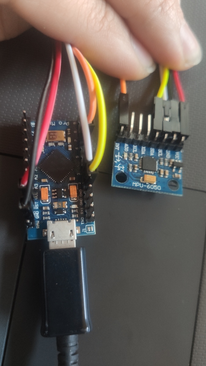
Jetzt bin ich grad etwas verwirrt, Board ist doch bestimmt dieses
Arduino Teil gemeint, also mein Pro Micro. Wenn das nicht gemeint ist,
bitte im Aufklärung was mit Board gemeint ist.
Den Schaltplan habe ich hochgeladen, der Leider den Thread gefüllt hatte
und Foto ist nun anbei, ich dachte das wäre optional. Weil ich das
definitiv richtig angestöpselt habe.
Und ich hatte oben beschrieben, das ich es an Pin 6 den Interrupt
gesteckt habe, es ist Pin 7.
Du hast Probleme mit einem MPU6050 Board. Da ist offenbar mehr drauf,
als nur der nackte Chip (mindestens eine LED). Um deine
Problembeschreibung nachzuvollziehen, brauchen wir die Unterlagen zu
diesem Board.

Ich würde zum Beispiel gerne mal hinterfragen, ob am I²C Bus Pull-Up
Widerstände fehlen und ob die Stromversorgung/Spannung passt.

Dein Programm solltest du auf wenige Zeilen reduzieren, die das Problem
zeigen. Durch Schrittweise Reduktion findest du heraus, was den Fehler
auslöst.

> Den Schaltplan habe ich hochgeladen

ich kann ihn nicht finden!

> Weil ich das definitiv richtig angestöpselt habe.

das wiederum kann ich mangels Plan un Unterlagen vom Modul nicht prüfen.
Der MPU6050 Chip kann jedenfalls nicht mit 5V betrieben werden. Du hast
die VCC Leitung aber an 5V angeschlossen. Auch der I²C Bus vom Chip
verträgt keine 5V.
Ich verstehe das grad nicht, das Modul ist doch für 3.3v und 5v
geeignet. Mein Arduino board arbeitet auf 5V.
Wenn es dieses Modul ist:
https://www.robotics.org.za/image/catalog/generic/GY-521/GY-521%20-%20Layout03.jpg,
dann hat es einen 3,3V Spannungsregler und Pull-Up Widerstände auf 3,3V.

Die LED müsste permanent leuchten, denn sie hängt an den 3,3V. Das
widerspricht aber deiner Aussage, dass es die Tx LED sei.
Erik H. schrieb:
> Ich verstehe das grad nicht, das Modul ist doch für 3.3v und 5v
> geeignet.

Woher soll ich das wissen? Soll ich das aus deinem Foto heraus lesen?
Welches Modul verwendest du? Ich brauche den Schaltplan davon!

Nur weil irgendein Chinese 5V in seinen Shop schreibt, heißt es noch
lange nicht, dass das Ding uneingeschränkt 5V kompatibel ist. Gerade die
Spannungspegel an den Signal-Leitungen sind hier oft ein Knackpunkt.

Ich habe zum Beispiel einige USBASP Programmieradpater, die knallhart 5V
Signale ausgeben, obwohl ich VCC per Jumper auf 3,3V eingestellt habe.
Das sind keine Produktionsfehler, sondern die werden immer noch so
produziert und verkauft! Aus dem Schaltplan geht das auch klar hervor -
works as (Kacke) designt.

Außerdem weiss ich immer noch nicht, um welche LED es geht. Wie ist sie
woran angeschlossen und was soll sie normalerweise anzeigen?

Anstatt zu diskutieren, besorge den Schaltplan von deinem MPU-6050 Modul
und reduziere dein Programm schrittweise, um den Fehler einzugrenzen.
Ziege und das kleinstmögliche Programm, so der Fehler noch auftritt.

Ich würde mal damit anfangen, die komplette USB Kommunikation raus zu
nehmen und stattdessen Debug Meldungen auf einem seriellen Port
auszugeben.
>Du hast Probleme mit einem MPU6050 Board. Da ist offenbar mehr drauf,
>als nur der nackte Chip (mindestens eine LED).

Nur nebnebei: Bei mir läuft dieses Modul, das ich von Pollin habe,
dauerhaft ohne Aussetzer mit 3,3V am Modul und 5V am AVR. Allerdings
habe ich nicht diese langen Kabel dazwischen. Lesen erfolgt im
Burst-Modus nach IRQ. Lochrasterplatte, handverdrahtet, Schutzdioden
drin gegen +5V und Abblock-Cs. Kein Display am Bus.

Mit Displays ist mir öfter mal der I2C-Bus hängen geblieben, mit diesem
Modul nicht.


mfG
Wenn der verdacht besteht, dass der I²C Bus hängt, schließe ich zwei
LEDs daran an, die bei LOW Pegel leuchten und stelle auf eine sehr
niedrige Übertragungsrate um (falls möglich). Meistens leuchtet im
Fehlerfall eine LED permanent.

Dann trenne ich einen Slave nach dem anderen ab, bis die LED aus geht.
Der war's dann wahrscheinlich Schuld. Dann kann ich weiter nachforschen,
warum dieser Slave sich wohl aufgehangen haben könnte.
Es gibt in der Schleife 2 verschiedene Aufgaben, die den Loop
unterbrechen. Beide habe ich mit Serielle ausgaben beobachtet und
zusätzlich mit LED Funktion. Das Programm wird richtig zwischen durch
abgebrochen, also nicht bei den 2 bestimmten Aufgaben, und lässt sich
nur mit Strom aus und wieder an aktivieren. Dann habe ich einfach mal
den Interrupt Pin entfernt. Jetzt läuft der Problemlos durch. DMP soll
ja nur mit Interrupt richtig funktionieren (berichtigt mich, wenn ich
falsch liege), aber es scheint noch alles gut zu laufen, also auch
saubere Daten. Ist Interrupt trotzdem noch wichtig? Wenn ja, dann müsste
ich mir ein neues Board kaufen, weil die meisten Interrupts auf SCL und
SDA laufen und Pin 7 irgendwie nicht richtig funktioniert, da es mein
Board zum Stillstand bringt.
Erik H. schrieb:
> weil die meisten Interrupts auf SCL und SDA laufen

Dieser Satz ergibt für mich keinen Sinn.

Ich sehe da nichts aufregendes:
1 | volatile bool mpuInterrupt = false; |
2 | |
3 | void dmpDataReady() |
4 | {
|
5 | mpuInterrupt = true; |
6 | }
|
7 | |
8 | attachInterrupt(digitalPinToInterrupt(INTERRUPT_PIN), dmpDataReady, RISING); |
Was kann da schon schief gehen? Eigentlich nichts, denke ich.
Interessanterweise wird diese Variable gar nicht gelesen, deswegen
stimme ich Dir zu, dass die Interruptleitung offenbar vollkommen unnütz
ist.

> Pin 7 irgendwie nicht richtig funktioniert, da es mein
> Board zum Stillstand bringt.

Da würde ich mal weiter nachforschen. Denn wenn der Pin vom Programm
letztendlich gar nicht benutzt wird, wie kann er dann ein Problem
auslösen? Irgend etwas wichtiges muss ich übersehen haben.

Messe mal die Spannung am Arduino Modul an Pin 7 (und GND). Vielleicht
ist die Verbindung defekt und da liegt eine undefinierte Spannung an
(weder eindeutig High noch Low) so dass der Interrupt ständig aufgerufen
wird und daher das Hauptprogramm zum Stillstand kommt.
Der Pin 7 hat 0 Volt. Der Interrupt Pin vom Modul hat 3,26V. Wann sich
der Interrupt tatsächlich einschaltet weis ich nicht, ist jedenfalls
nicht zu bemerken.

Alle Interrupts laufen auf ungünstige Pins. RX, TX, SDA und SCL.
https://neonaut.neocities.org/blog/images/pro-micro-fc73b3fa.png
Da steht nun auch Int.6 an Pin 7. Weis nicht was dieser Punkt zu
bedeuten hat.

Dann noch ne Frage nebenbei. Ich habe den "return;" rausgehaun, bei "if
(!dmpReady)" und eine Blinkende LED da rein gemacht. Warum Blinkt die
LED wenn die Serielle Verbindung unterbrochen ist, also wenn der Serial
Monitor geschlossen wurde? Es ist doch kein Programm da um dmpReady
umzuschalten auf False.
--Edit: Sie Blinkt auch wenn sie weg ist, am Ende ist ein LED Blinker
für jede Abfrage am Modul. Aber warum blinkt denn die so langsam wenn
die Verbindung zum Monitor getrennt wurde?
Erik H. schrieb:
> Der Pin 7 hat 0 Volt. Der Interrupt Pin vom Modul hat 3,26V

Wie kann das sein, die sind doch mit einem Kabel verbunden!?

> Alle Interrupts laufen auf ungünstige Pins. RX, TX, SDA und SCL.

Pin 7 (PE6, INT.6) ist doch OK. Alles gut.

> Ich habe den "return;" rausgehauen, bei
> if (!dmpReady) return;

Die Variable ist sowieso sinnlos, weil sie immer true ist:
> Serial.println(F("DMP ready! Waiting for first interrupt..."));
> dmpReady = true;

Da wird überhaupt nicht auf den ersten Interrupt gewartet.

> und eine Blinkende LED da rein gemacht.

Keine Ahnung was das bedeuten soll. Wie macht man eine LED in den
Quelltext rein? Ist das wirklich eine Blinkende LED, so wie diese:
https://www.reichelt.de/blink-led-5-mm-bedrahtet-2-pin-rot-5-mcd-60-led-bl-5mm-rt-p10205.html
? Es wird Zeit für vernünftige Pläne, damit wir wissen, wovon wir reden.

> Sie Blinkt auch wenn sie weg ist,

Wer blinkt wenn wer weg ist? Die LED ist weg und sie blinkt trotzdem?
Das ergibt keinen Sinn.

> Aber warum blinkt denn die so langsam wenn
> die Verbindung zum Monitor getrennt wurde?

Möglicherweise läuft dein Programm ohne USB Verbindung langsamer, weil
er Daten an den PC senden will, dieser sie aber nicht annimmt. Nach
einer gewissen zeit gibt das Framework dann auf und macht trotz
Kommunikationsfehler weiter.

Da musst du mal die Doku von dem entsprechenden Arduino Core lesen oder
in dessen Quelltexte gucken. Das ist halt die Krux bei Frameworks. Sie
sind toll, solange sie wie erwartet funktionieren. Aber wenn sie man
etwas unerwartetes machen, hat man besonders viel Mühe damit.
Danke, das wird es auch sein, dass der Programmablauf sehr langsam dann
läuft.

Da ich es an Pin 7 messen soll, habe ich die beiden getrennt. Zusammen
ergeben die aber auch 3,26V.
> DMP soll ja nur mit Interrupt richtig funktionieren (berichtigt mich, wenn ich
falsch liege), aber es scheint noch alles gut zu laufen, also auch saubere Daten.
Ist Interrupt trotzdem noch wichtig?

Ist die DMP-Software geladen ins Modul?

Ob der Interrupt wichtig ist, geht aus der Konfiguration des Moduls
hervor. Welche Betriebsart wurde eingestellt?

MfG
DMP wird vom Script aktiviert. Da es schon im Modul vorhanden ist.
Ich habe es nur so vernommen, das der interrupt notwendig ist, aber
bisher scheint es nicht notwendig zu sein, weil alles was ich vorhabe
super funktioniert.
Erik H. schrieb:
> Da ich es an Pin 7 messen soll, habe ich die beiden getrennt. Zusammen
> ergeben die aber auch 3,26V.

Ach so, na dann passt es ja. Ist eindeutig High.
Bitte melde dich an um einen Beitrag zu schreiben. Anmeldung ist kostenlos und dauert nur eine Minute.
Bestehender Account
Schon ein Account bei Google/GoogleMail? Keine Anmeldung erforderlich!
Mit Google-Account einloggen
Mit Google-Account einloggen
Noch kein Account? Hier anmelden.