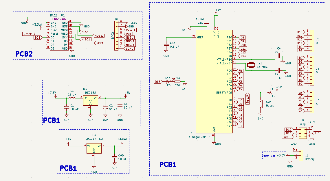
Hallo

can someone please check my design ? :)

I want to design 2 PCB , the first ist simple pcb like Arduino wich i
want to programming with ICSP

the second one just a simple RA-02


https://datasheet.lcsc.com/lcsc/2112021230_MICRONE-Nanjing-Micro-One-Elec-ME2188A50TG_C2925758.pdf

https://www.adafruit.com/product/2215

micrcontroller : Atmega328P-P

Is the Schematic True ?
Angehängte Dateien:
-

Unbenannt.PNG
15 KB
Ok, so you step-up the battery voltage from 3V3 to 5V using the ME2188
and use this directly as VCC for the ATmega328P? I never designed such a
step-up regulator, but I understand that the layout is quite critical,
so watch out for the recommendations. C3 I don't understand (but doesn't
hurt). C66 should probably be much bigger, like 4.7-100uF, or else there
is such a big capacitor missing from 3.3VA to GND. R13 is rather small,
will result in a very bright LED light shining, and might interfere with
the ISP programming; I'd rather use 1k. The ATmega328P needs two 100nF
close to the two power supplies, plus you forgot to connect pin 22 to
GND. I usually use 10k as pullup R1 for RESET, but 1k might work as
well. C4/C5 I usually use 18pF due to 2-4pF being contributed by the PCB
itself. I also prefer C33 to be 10nF instead of 100nF as this will allow
to switch the AREF source faster, but up to you. Usually there is also a
10mH coil between VCC and AVCC to reduce digital (and in your case
regulator) ripple impact on the analog measurements. Hope it helps.

Oh, one more thing out of curiosity: Why don't you use an Atmega328PB?

KR, Sebastian
Angehängte Dateien:
-

Unbenannt.PNG
16 KB
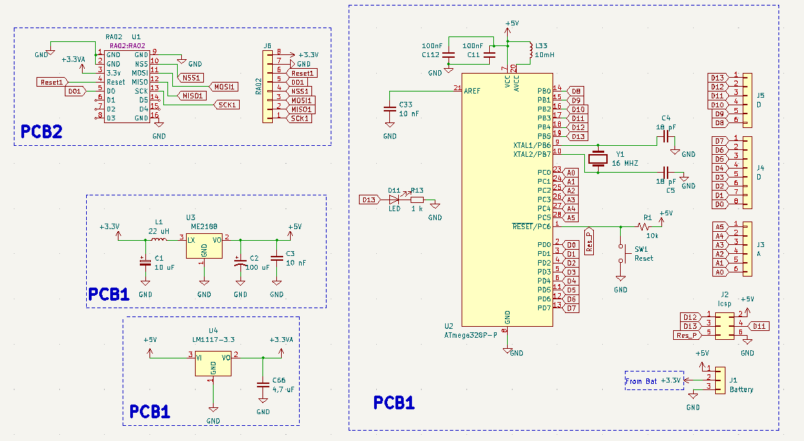
Thank you Sebastian ,

at first to test i will use THT microcontroller , then i want to using
SMD versiom Atmega328PB .
I correct my PCB now , like your Tipps .

Is it Ok now ?
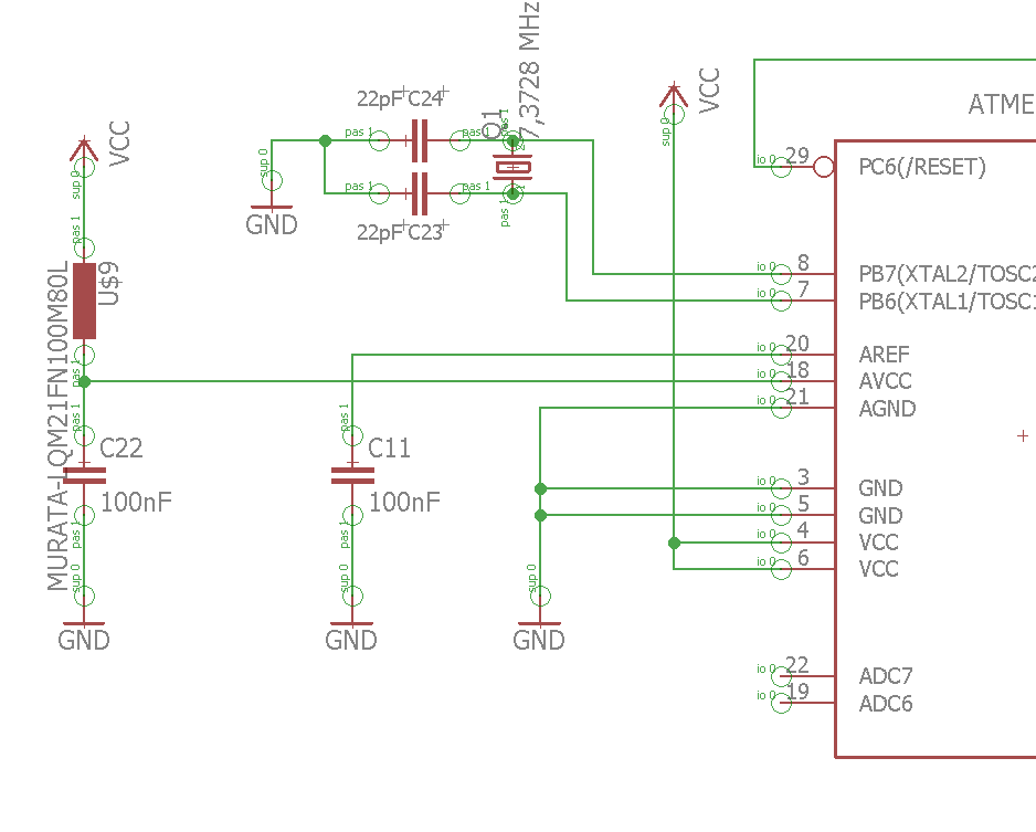
Sebastian W. schrieb:
> R13 is rather small

oh yes! 1k looks fine

if you want to use ISP pins as GPIO use 470 Ohm in line to external use
so a ISP can toggle ist!

358p ISP --- 470 Ohm --- LED or Input or other
      |----- to ISP connector

328p reset
https://www.kanda.com/files/isp_circuits.pdf
https://onlinedocs.microchip.com/pr/GUID-F626284A-58F0-4C25-A6F3-0EA5054F3E2B-en-US-6/index.html?GUID-B80B25FF-E9D7-4766-B562-DA197B8B938C
Note that Microchip/Atmel recommend a diode
in the reset circuit.

a diode at R1 and a capacitor to GND

a possible induktor to AVCC
https://www.mikrocontroller.net/attachment/373911/AVCC_Beschaltung.png
Angehängte Dateien:
-

avcc.png
56 KB
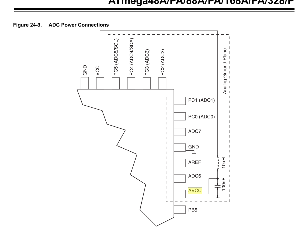
Mia schrieb:
> Is it Ok now ?

I made a typo, L33 should be 10uH, not 10mH. Also, the new C112 should
go from AVCC to GND, i.e. VCC - L33 - AVCC - C112 - GND. See also the
figure 24.9 in the Atmega328P datasheet (extract attached).

(For all the nitty-gritty details refer to
https://ww1.microchip.com/downloads/en/AppNotes/00002519A.pdf. But in my
opinion some of the recommendations in there are overkill.)

Watch out that the Pin 22 is still not connected to GND in your
schematics. It seems your Atmega328P model is lacking Pin 22.

One more item. Your ME2188 will make it that the system will continue to
run while draining the battery down to 0.95V (depending a bit on the
power consumption). This will probably harm the battery when it is a
rechargeable one. Maybe you should foresee a jumper which would connect
the +3.3V source to one of the analog ports of the Atmega328P so that
the software could at least detect that the battery goes flat and, I
don't know, warn the user or so ...

KR, Sebastian
Beitrag #7083100 wurde von einem Moderator gelöscht.
Bitte melde dich an um einen Beitrag zu schreiben. Anmeldung ist kostenlos und dauert nur eine Minute.
Bestehender Account
Schon ein Account bei Google/GoogleMail? Keine Anmeldung erforderlich!
Mit Google-Account einloggen
Mit Google-Account einloggen
Noch kein Account? Hier anmelden.