1 | ////// PCF8574 PINS
|
2 |
|
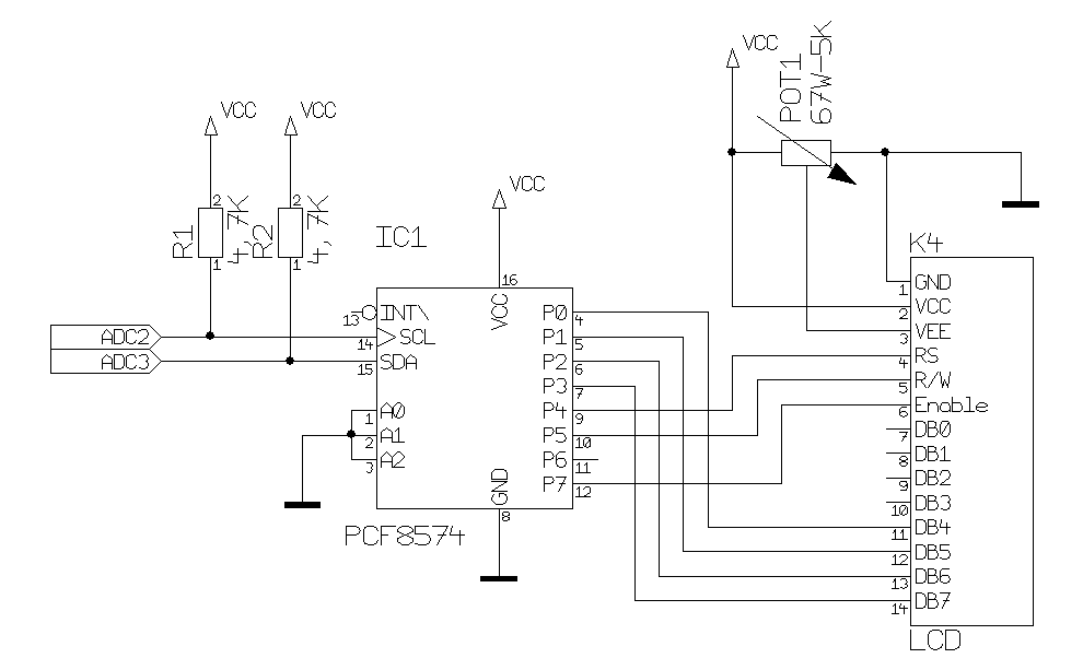
3 | #define LD4 0 // Pin to Data Bus 4
|
4 | #define LD5 1 // Pin to Data Bus 5
|
5 | #define LD6 2 // Pin to Data Bus 6
|
6 | #define LD7 3 // Pin to Data Bus 7
|
7 |
|
8 | #define LRS 4 // Pin to RS Pin (Register Select)
|
9 | #define LRW 5 // Pin to Read/Write Pin
|
10 | #define LEN 7 // Pin to Enable Pin
|
11 | #define LBL 6 // Backlight Pin, not used
|
12 |
|
13 | #define LCD_INIT {0b00000010,0b00001000, 0b00000000, 0b00001000, 0b00000000, 0b00000001, 0b00000000, 0b00000110, 0} // siehe Seite 18 Datenblatt
|
14 |
|
15 | void InitLCD(void)
|
16 | {
|
17 | unsigned char init[] = LCD_INIT;
|
18 | unsigned char i = 0;
|
19 |
|
20 | SetIOLCD(0, LCD_EN); // Start LCD Control, EN=0
|
21 | _delay_ms(15); // Wait LCD Ready
|
22 |
|
23 | CommandLCD( LCD_8BIT | (LCD_8BIT >> 4) );
|
24 | _delay_ms(5);
|
25 | CommandLCD( LCD_8BIT | (LCD_8BIT >> 4) );
|
26 | _delay_ms(1);
|
27 | CommandLCD( LCD_8BIT | (LCD_8BIT >> 4) );
|
28 | _delay_ms(1);
|
29 | CommandLCD( LCD_8BIT | (LCD_4BIT >> 4) );
|
30 | _delay_ms(1);
|
31 |
|
32 | while (init[i] != 0x00) // Hier sollten die 8 Kommandos geschickt werden
|
33 | {
|
34 | CommandLCD(init[i]); i++;
|
35 | }
|
36 | _delay_ms(1);
|
37 | }
|
38 |
|
39 | void CommandLCD(unsigned char command)
|
40 | {
|
41 | if (command == LCD_HOME) lineLCD = cursorLCD = 0x00;
|
42 | SetIOLCD(0, LCD_RS);
|
43 | SetDataLCD(command);
|
44 | }
|
45 |
|
46 | /* --------------
|
47 | LCD IO Ports schreiben
|
48 | \param setCommand an - oder auschalten
|
49 | \param bits zu setzende bits
|
50 | */
|
51 | void SetIOLCD(unsigned char setCommand, unsigned char bits)
|
52 | {
|
53 | if (setCommand == 1)
|
54 | portLCD |= bits;
|
55 | else
|
56 | portLCD &= ~bits;
|
57 |
|
58 | i2c_start_wait(LCD_DEV+0);
|
59 | if (i2c_write(portLCD)) uart_puts("i2c Write failed.\n");
|
60 | i2c_stop();
|
61 | }
|
62 | /*------------
|
63 | LCD Daten schreiben
|
64 | \param data auszugebende Date
|
65 | */
|
66 | void SetDataLCD(unsigned char data)
|
67 | {
|
68 | unsigned char dataPins; // Pin Compatibility
|
69 |
|
70 | // Set First Nibble Data to DataPins on PCF8574
|
71 | dataPins &= 0x00;
|
72 | dataPins |= ((data & 0x80) >> 7) << LD7;
|
73 | dataPins |= ((data & 0x40) >> 6) << LD6;
|
74 | dataPins |= ((data & 0x20) >> 5) << LD5;
|
75 | dataPins |= ((data & 0x10) >> 4) << LD4;
|
76 |
|
77 | SetIOLCD(0, LCD_D4 | LCD_D5 | LCD_D6 | LCD_D7); //Clear old Data Bit[7..4])
|
78 | SetIOLCD(1, dataPins); // Strobe High Nibble Command
|
79 | SetIOLCD(1, LCD_EN); // Enable ON
|
80 | _delay_ms(1);
|
81 | SetIOLCD(0, LCD_EN); // Enable OFF
|
82 |
|
83 | // Set Second Nibble Data to DataPins on PCF8574
|
84 | dataPins &= 0x00;
|
85 | dataPins |= ((data & 0x08) >> 3) << LD7;
|
86 | dataPins |= ((data & 0x04) >> 2) << LD6;
|
87 | dataPins |= ((data & 0x02) >> 1) << LD5;
|
88 | dataPins |= ((data & 0x01) >> 0) << LD4;
|
89 |
|
90 | SetIOLCD(0, LCD_D4 | LCD_D5 | LCD_D6 | LCD_D7); // Clear old LCD Data (Bit[7..4])
|
91 | SetIOLCD(1, dataPins); // Strobe Low Nibble Command
|
92 | SetIOLCD(1, LCD_EN); // Enable ON
|
93 | _delay_ms(1);
|
94 | SetIOLCD(0, LCD_EN); // Enable OFF
|
95 | _delay_ms(1); // Wait LCD Busy
|
96 | }
|