IRMP auf STM32 – stark vereinfachte Bauanleitung
Copyright (C) 2017 Jörg Riechardt
Vorwort
Diese Anleitung hat das Ziel, den Bau des Empfängers so einfach wie möglich zu machen.
Es sind allerdings für die Pins des Maple Mini und das Einschaltkabel Basis-Lötkenntnisse nötig.
Hier nur für IR Empfang und PC Einschalten.
Kauf
Man braucht
- einen Maple Mini Clone [1], Stichwort für ebay: „ Maple Mini“
- DuPont Steckverbinder weiblich – weiblich, Stichwort: DuPont 20cm female female
- DuPont Steckverbinder weiblich – männlich, Stichwort: DuPont 10cm female male
- TSOP4838 (je nach benötigter Frequenz), Stichwort: TSOP4838
- einen 220 Ohm Widerstand, Stichwort: 220 ohm metal film
[1] http://wiki.stm32duino.com/index.php?title=Maple_Mini
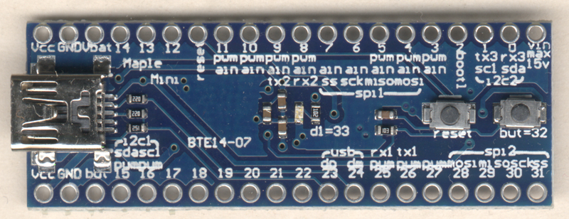
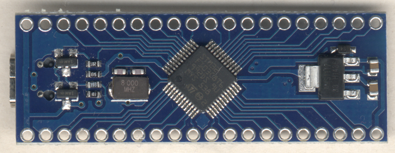
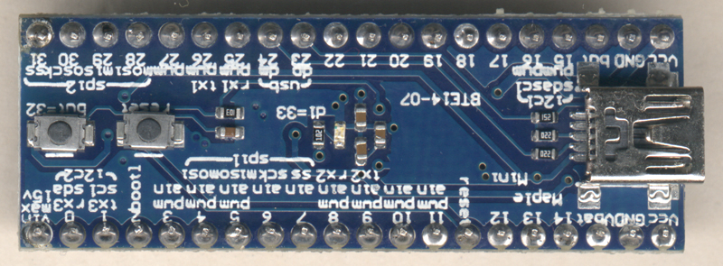
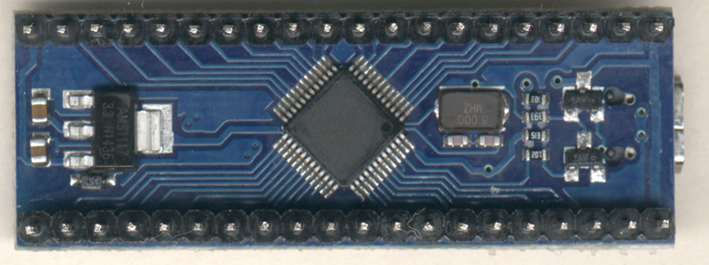
Ein neuer Maple Mini von beiden Seiten.
Hier sind alle Pins eingelötet. Es reicht aber, die 4 benötigten Pins einzulöten.
Firmware flashen (Linux/Windows)
Mit dem auf dem Maple Mini vorhandenem Bootloader wird die Firmware geflasht.
Aus https://github.com/j1rie/IRMP_STM32/tree/master/binaries/firmware_for_bootloader/SimpleCircuit die Maple Mini Firmware xxx_MapleMini_SC_BL_jrie.bin holen.
Aus https://github.com/j1rie/IRMP_STM32/tree/master/bootloader FlashDFUSe.sh bzw FlashDFUSe.bat holen.
Auf der Kommandozeile ausführen
- Linux: FlashDFUSe.sh xxx_MapleMini_SC_BL_jrie.bin
- Windows: FlashDFUSe.bat xxx_MapleMini_SC_BL_jrie.bin
und den Maple Mini anstecken.
Am Ende sieht man: Download [=========================] 100%.
Kabel löten
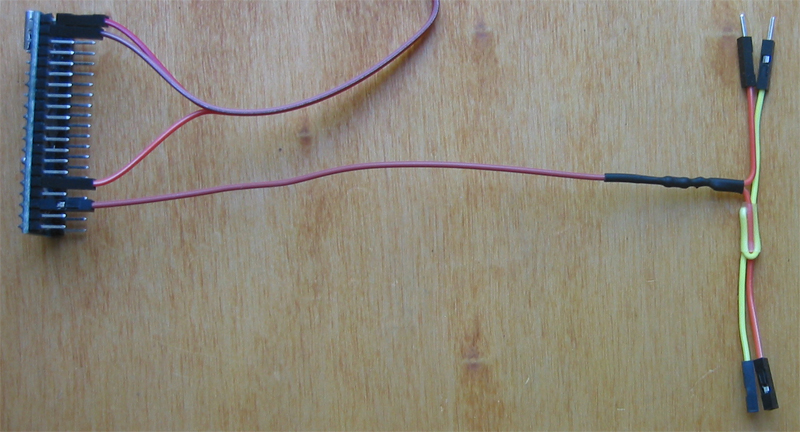
Ein 10cm Kabel wird aufgetrennt, die beiden Enden miteinander und dem 220 Ohm Widerstand verbunden, das andere Ende des Widerstands wird mit dem 20cm Kabel, dessen eine Buchse abgeschnitten ist, verbunden. Lötstellen einschrumpfen, das andere 10cm Kabel mittels Schrumpfschlauch anheften.
Kabel anschließen
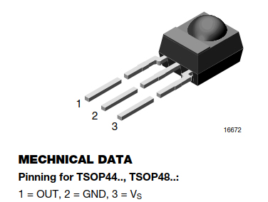
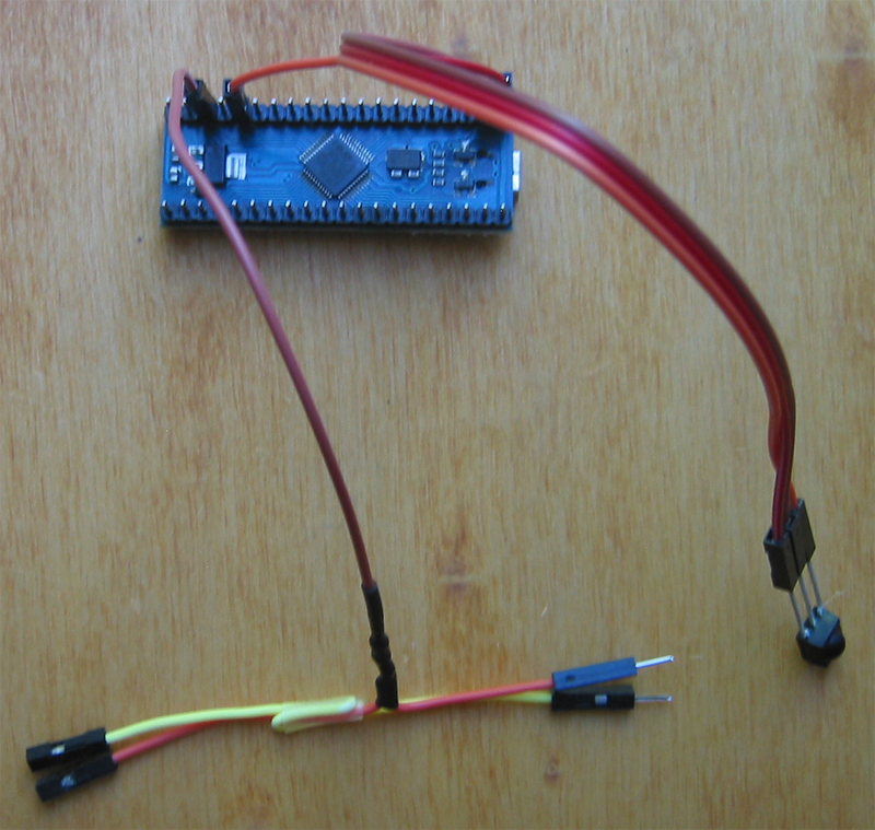
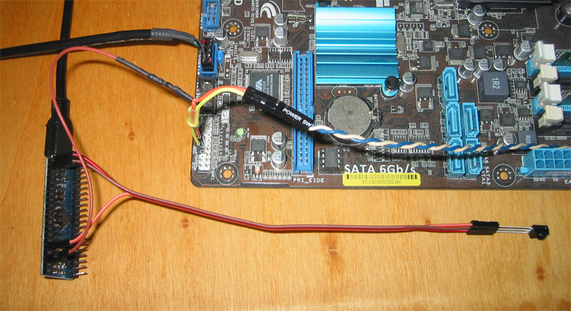
Der TSOP ist direkt mit den entsprechenden Pins verbunden, das Kabelpaar wird zwischen die Mainboard-Einschaltpins und den Stecker vom Einschalter eingeschleift und der aktive Einschaltpin des Mainboards wird über den Widerstand (220 Ohm) herunter gezogen.
Einschaltpin = B10 = „1“ ↔ 220 Ohm
IR-in-Pin = B0 = „3“ ↔ TSOP out
„VCC“ ↔ TSOP Vs
„GND“ ↔ TSOP GND
Wakeup anlernen
Falls das erste Wakeup leer ist, werden automatisch die ersten empfangenen IR Daten ins erste Wakeup gespeichert.
Man kann die neuen Wakeup IR Daten auch per Fernbedienung mit dem Konfigurationsprogramm eingeben.
Testen (Linux/Windows)
Windows: Aus https://github.com/j1rie/IRMP_STM32/tree/master/binaries/stm32IRconfig_gui/Windows stm32IRconfig_gui.exe holen, Empfänger anschliessen, stm32IRconfig_gui starten, "receive mode" drücken und testen
oder aus https://github.com/j1rie/IRMP_STM32/tree/master/binaries/stm32IRconfig/Windows stm32IRconfig.exe holen, ST-Link anschliessen, stm32IRconfig starten, m eingeben für Monitor-Modus und testen.
EventGhost mit Generic HID unterstützt den Empfänger.
Bitte beachten: Eingeschaltet wird nur, wenn der PC aus ist.
Linux: EasyVDR und yaVDR unterstützen den Empfänger und haben passende Pakete. Sonst muss man selbst bauen.
Motherboard-Test
Wer prüfen will, ob das Motherboard geeignet ist, macht folgenden Test an den Einschaltpins des Mainboards.
Man misst, ob der eine Pin an Masse liegt und ob der andere ca. +3,3V oder +5V führt. Dann schließt man beide über ein Multimeter kurz, und misst den Strom. Der beträgt üblicherweise nur wenige mA, und solange es unter 25mA sind, ist der Test bestanden.
Bisher gab es noch keine Rückmeldung über ein ungeeignetes Board.
Fertige Empfänger kaufen
Wer nicht löten will:
https://www.vdr-portal.de/forum/index.php?thread/130398-irmp-stm32-usb-ir-empf%C3%A4nger/
Diskussion
Fragen und Kommentare können hier gestellt werden: https://www.vdr-portal.de/forum/index.php?thread/123572-irmp-auf-stm32-ein-usb-ir-empf%C3%A4nger-sender-einschalter-mit-wakeup-timer/
IRMP on STM32 – much simplified construction manual
Foreword
These instructions aim at making building the receiver as simple as possible.
Basic solder skills are needed though for the Maple Mini pins and the powerswitch cable.
This is only for IR reception and PC power on.
Buy
You need
- a Maple Mini Clone [1], keyword for ebay: „ Maple Mini“
- DuPont connector female – female, keyword: DuPont 20cm female female
- DuPont connector female – male, keyword: DuPont 10cm female male
- TSOP4838 (depending on needed frequency), keyword: TSOP4838
- a 220 ohm resistor, keyword: 220 ohm metal film
[1] http://wiki.stm32duino.com/index.php?title=Maple_Mini
Both sides of a new Maple Mini.
All Pins are soldered in here. It would be sufficient to solder only the 4 needed pins, though.
Firmware flashing
The Firmware gets flashed with the bootloader present on the Maple Mini.
Get the Maple Mini Firmware xxx_MapleMini_SC_BL_jrie.bin from https://github.com/j1rie/IRMP_STM32/tree/master/binaries/firmware_for_bootloader/SimpleCircuit
Get FlashDFUSe.sh resp. FlashDFUSe.bat from https://github.com/j1rie/IRMP_STM32/tree/master/bootloader
Execute on the command line
- Linux: FlashDFUSe.sh xxx_MapleMini_SC_BL_jrie.bin
- Windows: FlashDFUSe.bat xxx_MapleMini_SC_BL_jrie.bin
and connect the Maple Mini.
When finished you see: Download [=========================] 100%.
Solder Cables
Split a 10cm cable, connect both ends and the 220 ohm resistor, connect the other end of the resistor with the 20cm cable, from which one socket is cut off. Shrink the solder connections, attach the other 10cm cable with shrink tube.
Connect Cables
The TSOP is directly connected to the corresponding pins, the pair of cables is inserted between the power on pins of the mainboard and the connector from the power button and the mainboard's active power switch pin is pulled down via the resistor (220 ohm).
Power on pin = B10 = „1“ ↔ 220 ohm
IR-in-Pin = B0 = „3“ ↔ TSOP out
„VCC“ ↔ TSOP Vs
„GND“ ↔ TSOP GND
Learning Wakeup
If the first wakeup is empty, the first received IR data will be stored into the first wakeup.
You could enter the new wakeup IR data as well via remote control with the configuration program.
Testing (Linux/Windows)
Windows: Get stm32IRconfig_gui.exe from https://github.com/j1rie/IRMP_STM32/tree/master/binaries/stm32IRconfig_gui/Windows , connect the receiver, start stm32IRconfig_gui, press "receive mode" and test
or get stm32IRconfig.exe from https://github.com/j1rie/IRMP_STM32/tree/master/binaries/stm32IRconfig/Windows , connect the receiver, start stm32IRconfig, enter m for monitor mode and test.
EventGhost with Generic HID supports the receiver.
Please note: Switching on only happens, if the PC is powered off.
Linux: EasyVDR and yaVDR support the receiver and have the needed packets. Otherwise you need to build them yourself.
Check your motherboard
To check, if your motherboard is compatible, you can test the powerswitch pins of the mainboard like this.
Measure if one pin is on ground and the other on ca. +3,3V or +5V. Then short-circuit both via a multimeter, and measure the current. It is usually only few mA, and as long as it is below 25 mA, the test is passed.
So far there was no report on an incompatible motherboard.
Buy ready to use receivers
In case you don‘t want to solder:
https://www.vdr-portal.de/forum/index.php?thread/130398-irmp-stm32-usb-ir-empf%C3%A4nger/
Discussion
Questions and comments can be put here: https://www.vdr-portal.de/forum/index.php?thread/123572-irmp-auf-stm32-ein-usb-ir-empf%C3%A4nger-sender-einschalter-mit-wakeup-timer/
