IRMP auf STM32 - Bauanleitung
Copyright (C) 2014-2015 Jörg Riechardt
Vorwort
Diese Anleitung ist für zwei ST-Links. Man kann auch ein Developer Board und einen USB-Seriell-TTL Adapter nehmen. Die ST-Links im USB Stick Gehäuse sind wie rote ST-Links beschaltet.
Kauf
Man braucht zwei ST-Link V2 Emulatoren.
Eine ebay Suche nach "ST-Link V2 Emulator" zeigt, was es gerade gibt.
Ich habe meine Roten beim Verkäufer e_goto für 4.99 $ gekauft, also ca. 4 €.
Die Blauen gibt es bei http://www.aliexpress.com/item/STLINK-V2-STM8-STM32-emulator-programmer-mini-STLINK-downloader/1446941850.html

In den Blauen habe ich 3 Pins zusätzlich eingelötet für TCK und TMS.
Beim Blauen sind CLK und TCK sowie DIO und TMS vertauscht.
Firmware bauen (Linux)
gcc-arm-none-eabi wird zum Kompilieren gebraucht. Wenn es nicht schon über die Distribution verfügbar ist, kann man es sich von https://launchpad.net/gcc-arm-embedded/+download holen.
git clone git://github.com/j1rie/IRMP_STM32.git IRMP_STM32
cd IRMP_STM32
cd F103
./make
Firmware bauen (Windows)
https://github.com/j1rie/IRMP_STM32
IRMP_STM32-master.zip herunter laden und auspacken
in scripts prepare.bat ausführen
IR.coproj in CooCox laden und kompilieren
Programmer

Der Blaue als Programmer

Der Rote als Programmer
Target

Der Blaue als Target

Der Rote als Target.
Damit der TSOP an SWIM funktioniert, muss möglicherweise der PullUp an SWIM entfernt werden (Bild unten). Ich habe einen (uralten) TSOP, der mit PullUp nicht funktioniert. Ein TSOP 34136 funktioniert aber auch mit dem Widerstand.
Wenn man einen Roten als Programmer und einen Blauen als Target nimmt, muss man nichts löten (wenn man auf den Bootloader verzichtet). Oder man kann auch einfach während des Flashens zwei Kontaktstifte an SWDIO und SWCLK pressen.
Flashen (Linux)
Programmer und Target werden verbunden, SWCLK - SWCLK, SWDIO - SWDIO, 3,3V - 3,3V, Gnd -Gnd.
Für das erste Flashen ist es nötig, den Controller mit folgendem openocd-Befehl zu entsperren:
$ openocd -f interface/stlink-v2.cfg -f target/stm32f1x_stlink.cfg -c "init" -c "halt" -c "stm32f1x unlock 0" -c "shutdown"
Danach kann die Firmware geflasht werden:
git clone git://github.com/texane/stlink.git
cd stlink
./autogen.sh
./configure
./make
./st-flash erase
./st-flash --reset write /IRMP_STM32/F103C8/firmware.bin 0x8000000
In manchen Fällen ist es nötig, zu Beginn des Flashens den ST-Link zu resetten. Dazu muss die Stelle im Bild auf Masse gezogen werden und kurz nach Absetzen des Flash Befehls wieder los gelassen werden.
Flashen (Windows)
Mit dem STM32 ST-LINK Utility.
Verbinden und resetten wie unter Linux.
Entsperren: -> Target -> Option Bytes, die Read Out Protection auf Disabled stellen.
Flashen: -> Target -> Program & Verify

Für Reset das rot Umrahmte auf Masse ziehen.

Für Reset das gelb Umrahmte auf Masse ziehen. Grün umrahmt der PullUp an SWIM.
Anschlüsse

Den Blauen verbinden.

Den Roten verbinden.
Wakeup anlernen
Falls das erste Wakeup leer ist, werden automatisch die ersten empfangenen IR Daten ins erste Wakeup gespeichert.
Für das erneute Anlernen zieht man den Wakeup Reset Pin kurz auf Masse und drückt in den nächsten 5 Sekunden die Taste, die angelernt werden soll.
Man kann die neuen Wakeup IR Daten auch manuell oder per Fernbedienung mit dem Konfigurationsprogramm eingeben.
Die Wakeup-Taste löst bei laufendem PC nicht den Optokoppler aus, wird aber über irmplircd weiter geleitet. Wenn die Wakeup-Taste im VDR als Power-Taste angelernt ist, kann man darüber den PC herunter fahren.
Testen (Linux)
Mit stm32IRconfig_gui: ST-Link anschliessen, stm32IRconfig_gui starten, "receive mode" drücken und testen.
Mit stm32IRconfig: ST-Link anschliessen, stm32IRconfig starten, m eingeben für Monitor-Modus und testen.
Mit irmplircd: ST-Link anschliessen, irmplircd und irw starten und testen.
Bitte beachten: Geschaltet wird am (D)IO/PwrSwitch-Pin nur, wenn der PC aus ist.
Testen (Windows)
Mit stm32IRconfig_gui: ST-Link anschliessen, stm32IRconfig_gui starten, "receive mode" drücken und testen.
Mit stm32IRconfig: ST-Link anschliessen, stm32IRconfig starten, m eingeben für Monitor-Modus und testen.
Mit SimpleHIDWrite: ST-Link anschliessen, in SimpleHIDWrite auswählen und testen.
http://janaxelson.com/hidpage.htm#tools
Bitte beachten: Geschaltet wird am (D)IO/PwrSwitch-Pin nur, wenn der PC aus ist.
Aufsteckplatine
Es gibt eine Aufsteckplatine. Mit dem Steckverbinder auf der einen Seite passt sie auf den Blauen, und mit dem Steckverbinder auf der anderen Seite passt sie auf den Roten.
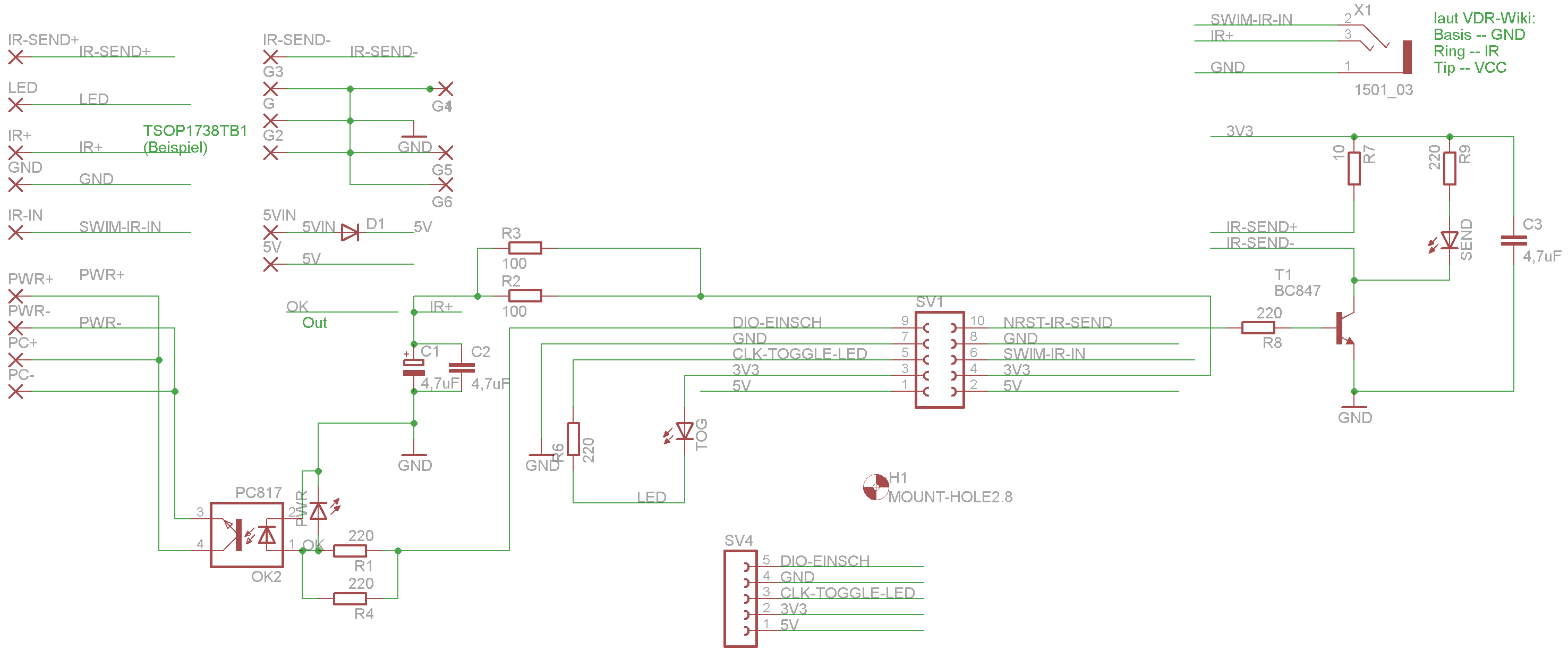
Schaltplan
http://www.vdr-portal.de/board73-marktplatz/board75-verkaufen/p1220193-usb-ir-receiver-inkl-einschalter-opensource-sw-hw/#post1220193
Es ist wichtig, die Polarität des Optokopplers zu beachten. Die Kontakte, die näher am IRin sind, sind Plus.
Bootloader (Linux)
git clone -b unify_platforms git://github.com/j1rie/maple-bootloader.git
cd maple-bootloader
make Platform=Dev (Developer Board) bzw.
make Platform=Red (Roter) bzw.
make Platform=Blue (Blauer)
Dann ./build/maple_boot.bin flashen.
Danach wird dann so geflasht:
Zuerst /path/FlashDFUSe.sh /path/neueFirmware.bin* ausführen,
dann den ST-Link anstecken.
(*) Die Firmware muss mit Bootloader=1 kompiliert sein.

Der Blaue mit Pulldown Widerstand zwischen USBDP und USB Disconnect Pin.


Der Rote mit Pulldown Widerstand zwischen USBDP und USB Disconnect Pin.
Automatisches Starten/Beenden von irmplircd(*) beim An/Abstecken mit systemd
80-irmp.rules aus IRMP_STM32/irmplircd/ nach /etc/udev/rules.d/ kopieren.
irmplircd.service aus IRMP_STM32/irmplircd/ nach /etc/systemd/system/ kopieren.
Service aktivieren mit 'systemctl enable irmplircd.service'.
Die Pfade zu irmplircd und irmp_stm32.map in irmplircd.service falls nötig anpassen.
Die Übersetzungstabelle irmp_stm32.map kann mit stm32IRconfig_gui erzeugt und angepasst werden.
(*) https://github.com/realglotzi/irmplircd
Minimalistischer Aufbau für erfahrene Bastler
Nur für IR Empfang und PC Einschalten. Der TSOP ist direkt mit den entsprechenden Pins verbunden und der aktive Einschaltpin des Mainboards wird über den Widerstand (220 Ohm) herunter gezogen (SimpleCircuit = 1).
Bitte vorsichtig sein und nicht das Motherboard beschädigen!
Entweder direkt über den Schutzwiderstand ans Einschalter-Kabel …


… oder an ein Zwischenstück, das zwischen Board und Einschalter-Kabel eingefügt wird.


Zum Überprüfen, ob man den Optokoppler weglassen kann, macht man folgenden Test an den Einschaltpins des Mainboards.
Man misst, ob der eine Pin an Masse liegt und ob der andere ca. +3,3V oder +5V führt. Dann schließt man beide über ein Multimeter kurz, und misst den Strom. Der beträgt üblicherweise nur wenige mA, und solange es unter 25mA sind, ist der Test bestanden.
Perfektionisten können ein hoch gedrehtes Poti an beide Pins klemmen, es langsam herunter drehen und messen, ab welchem Widerstand das Board einschaltet. Dann kann man einen entsprechenden Schutzwiderstand nehmen. Sonst nimmt man 220 Ohm, nachdem man geprüft hat, dass das Board an geht, wenn man beide Pins damit überbrückt. Wer sich sicher ist, dass er sich beim Zusammenstecken nie vertut, kann den Widerstand auch weglassen.
In Umgebungen mit vielen Störungen kann es besser sein, den TSOP über ein RC-Glied zu verbinden, siehe http://www.vishay.com/docs/82492/tsop312.pdf .
IRMP on STM32 - Construction manual
Foreword
This manual is for two ST-Links. You could use a developer board and a USB-serial-TTL adapter instead. The ST-Links in USB stick cases are wired like red ST-Links.
Buy
You need two ST-Link V2 emulators.
An ebay search for "ST-Link V2 emulator" shows, what is available.
I bought the red one from seller e_goto for 4.99 $, so ca. 4 €.
The blue ones you get at http://www.aliexpress.com/item/STLINK-V2-STM8-STM32-emulator-programmer-mini-STLINK-downloader/1446941850.html
There are three pins soldered into the blue one for TCK and TMS.
On the blue one CLK and TCK and also DIO and TMS are exchanged.
Firmware Compilation (Linux)
gcc-arm-none-eabi is needed for compilation. If it is not already available through your distribution, you can get it from https://launchpad.net/gcc-arm-embedded/+download .
git clone git://github.com/j1rie/IRMP_STM32.git IRMP_STM32
cd IRMP_STM32
cd F103
./make
Firmware Compilation (Windows)
https://github.com/j1rie/IRMP_STM32
download and extract IRMP_STM32-master.zip
run prepare.bat in scripts
open IR.coproj in CooCox and compile
Programmer
The blue as programmer.
The red as programmer.
Target
The blue as target.
The red as target.
For the TSOP to work on SWIM, it might be necessary to remove the pullup on SWIM (image below). I have a (very old) TSOP, which does not work with the pullup. But a TSOP 34136 works even with the resistor.
With a red as programmer and a blue as target, you don't need to solder (if you go without the bootloader). Or you could simply press two contact pins against SWDIO und SWCLK during flashing.
Flashing (Linux)
Connect programmer and target, SWCLK - SWCLK, SWDIO - SWDIO, 3,3V - 3,3V, Gnd -Gnd.
You need to unlock the controller before the first flash with an openocd command:
$ openocd -f interface/stlink-v2.cfg -f target/stm32f1x_stlink.cfg -c "init" -c "halt" -c "stm32f1x unlock 0" -c "shutdown"
Then flash the firmware:
git clone git://github.com/texane/stlink.git
cd stlink
./autogen.sh
./configure
./make
./st-flash erase
./st-flash --reset write /IRMP_STM32/F103C8/firmware.bin 0x8000000
In some cases it is necessary, to reset the ST-Link at the beginning of flashing. You need to pull the marked area in the image to ground and release it shortly after the flash command.
Flashing (Windows)
With the STM32 ST-LINK utility.
Connection and reset as in linux section.
Unlocking: -> Target -> Option Bytes, put Read Out Protection to Disabled.
Flashen: -> Target -> Program & Verify
For reset pull the red marked to ground.
For reset pull the yellow marked to ground. Green marked the pullup on SWIM.
Connections
Connect the blue.
Connect the red.
Learning Wakeup
If the first wakeup is empty, the first received IR data will be stored into the first wakeup.
To renew learning pull the wakeup reset pin shortly to ground and push within the next 5 seconds the button, which shall be learned.
You could enter the new wakeup IR data as well manually or via remote control with the configuration program.
If the PC is powered on, the wakeup button does not trigger the optocoupler, but is passed on by irmplircd. If the wakeup button has been trained in VDR as power button, you can power down the PC by it.
Testing (Linux)
With stm32IRconfig_gui: connect the ST-Link, start stm32IRconfig_gui, press "receive mode" and test.
With stm32IRconfig: connect the ST-Link, start stm32IRconfig, enter m for monitor mode and test.
With irmplircd: connect the ST-Link, start irmplircd and irw and test.
Please note: The (D)IO/PwrSwitch-pin switches only, if the PC is powered off.
Testing (Windows)
With stm32IRconfig_gui: connect the ST-Link, start stm32IRconfig_gui, press "receive mode" and test.
With stm32IRconfig: connect the ST-Link, start stm32IRconfig, enter m for monitor mode and test.
With SimpleHIDWrite: connect the ST-Link and select it in SimpleHIDWrite and test.
http://janaxelson.com/hidpage.htm#tools
Please note: The (D)IO/PwrSwitch-pin switches only, if the PC is powered off.
Expansion Board
There is a expansion board. With the connector on one side, it fits onto the blue, and with the connector on the other side it fits onto the red.
Circuit
http://www.vdr-portal.de/board73-marktplatz/board75-verkaufen/p1220193-usb-ir-receiver-inkl-einschalter-opensource-sw-hw/#post1220193
It is important, to pay attention to the polarity of the optocoupler. Those contacts, that are closer to IRin, are plus.
Bootloader (Linux)
git clone -b unify_platforms git://github.com/j1rie/maple-bootloader.git
cd maple-bootloader
make Platform=Dev (Developer board) or
make Platform=Red (Red) or
make PPlatform=Blue (Blue)
Then flash ./build/maple_boot.bin.
After that you flash like this:
First run /path/FlashDFUSe.sh /path/newFirmware.bin*,
then connect the ST-Link.
(*) The firmware needs to be compiled with Bootloader=1.
The blue with pulldown resistor between USBDP and USB disconnect pin.
The red with pulldown resistor between USBDP and USB disconnect pin.
Automatic Start/Stop of irmplircd(*) on Re/Disconnect with systemd
Copy 80-irmp.rules from IRMP_STM32/irmplircd/ to /etc/udev/rules.d/ .
Copy irmplircd.service from IRMP_STM32/irmplircd/ to /etc/systemd/system/ .
Activate service by 'systemctl enable irmplircd.service'.
Adapt paths to irmplircd and irmp_stm32.map in irmplircd.service if needed.
The translation tabelle irmp_stm32.map can be created and adapted with stm32IRconfig_gui.
(*) https://github.com/realglotzi/irmplircd
Minimalistic assembly for experienced users
Only for IR reception and turning the PC on. The TSOP is directly connected to the corresponding pins and the mainboard's active power switch pin is pulled down via the resistor (220 ohms) (SimpleCircuit = 1).
Please be careful and don't damage your motherboard!
Either directly via the protection resistor to the powerswitch-cable ...
… or to an inbetween piece, which gets inserted between board and powerswitch-cable.
To check, if it is possible to omit the optocoupler, you can test the powerswitch pins of the mainboard like this.
Measure if one pin is on ground and the other on ca. +3,3V or +5V. Then short-circuit both via a multimeter, and measure the current. It is usually only few mA, and as long as it is below 25 mA, the test is passed.
Perfectionists could connect a high turned pot to both pins, turn it slowly down and measure, since which resistance the board switches on. Then you take a corresponding protection resistor. Otherwise you take 220 ohm, after checking, that the board switches on, when both pins are connected through it. If you are shure to never make a mistake while putting together, you could omit the resistor as well.
Within environments with heavy interferences it might be better to connect the TSOP via a RC element, see http://www.vishay.com/docs/82492/tsop312.pdf .