Hallo,

ich hin gerade dabei mich in LCD - Routinen einzuarbeiten. Genauer bin
ich ganz am Anfang...

Ich habe mir ein

- Atmel Evaluaion Board V2.01
- Atmel Addon Board V1.0
- AVR Dragon besorgt
- ATMega 16

Das "System funktioniert" ich kann auf den uC zugreifen und ihn
programmieren.

Mein Ziel ist ADC - Werte am Display auszugeben. ADC Wandlung
funktioniert bereits sehr genau.

Kann mir jemand ein kurzes Programm für die LCD - Ansteuerung zur
Verfügung stellen mit dem ich meine ersten Schritte laufen kann...

Irgendwie komme ich mit dem Tutorial auf dieser Seite nicht zurecht. Der
Kompiler gibt lauter Fehler aus.

Vielen Dank
Mit einem atmega8 gelaufen...

Die Jumper auf dem Addon-Board sind alle offen zu lassen, stattdessen
Kabel stecken, wie im Kommentar beschrieben!

Hauptprogramm:
1 | // Time-stamp: "29.06.09 11:04 pollin_evalboard_addon_LCD2x16.c klaus@wachtler.de"
|
2 | //
|
3 | // Testprogramm für LCD auf Pollin-Addon-Board zum
|
4 | // Pollin-AVR-Evaluationboard oder frei verdrahtet im 4-bit-Modus
|
5 | // lt. www.mikrocontroller.net.
|
6 | //
|
7 | // Auf dem Addon-Board ist ein LCD 2x16 mit HDC44780.
|
8 | // Anschluß (Jumperleiste 1:1 gesteckt):
|
9 | //
|
10 | // Folgende Kabel auf Addon-Board stecken:
|
11 | // - PA1 (ATMega8: PC0) -> LCD DB4
|
12 | // - PA2 (ATMega8: PC1) -> LCD DB5
|
13 | // - PA3 (ATMega8: PC2) -> LCD DB6
|
14 | // - PA4 (ATMega8: PC3) -> LCD DB7
|
15 | // - PA5 (ATMega8: PC4) -> LCD RS
|
16 | // - PA6 (ATMega8: PC5) -> LCD E
|
17 | // - GND -> R/W
|
18 | //
|
19 | // Bei freier Verdrahtung müssen folgende Verbindungen existieren:
|
20 | // LCD AVR
|
21 | // VSS 1-----GND
|
22 | // VDD 2-----+5V
|
23 | // VEE 3--Abgriff Poti 10k zw. GND und +5V
|
24 | // RS 4---------------------------------------------LCD-RS PC4
|
25 | // R/W 5-----GND
|
26 | // E 6---------------------------------------------LCD-E PC5
|
27 | // DB0 7-NC
|
28 | // DB1 8-NC
|
29 | // DB2 9-NC
|
30 | // DB3 10-NC
|
31 | // DB4 11---------------------------------------------LCD-DB4 PC0
|
32 | // DB5 12---------------------------------------------LCD-DB5 PC1
|
33 | // DB6 13---------------------------------------------LCD-DB6 PC2
|
34 | // DB7 14---------------------------------------------LCD-DB7 PC3
|
35 | // LED-A 15--R 220Ohm--+5V
|
36 | // LED-K 15-----GND
|
37 | //
|
38 | //
|
39 | // ATMega8:
|
40 | //
|
41 | // +---------+
|
42 | // (/Reset) PC6-| 1 28 |-PC5 (ADC5/SCL)
|
43 | // (RxD) PD0-| 2 27 |-PC4 (ADC4/SDA)
|
44 | // (TxD) PD1-| 3 26 |-PC3 (ADC3)
|
45 | // (INT0) PD2-| 4 25 |-PC2 (ADC2)
|
46 | // (INT1) PD3-| 5 24 |-PC1 (ADC1
|
47 | // (XCK/T0) PD4-| 6 23 |-PC0 (ADC0)
|
48 | // VCC-| 7 22 |-GND
|
49 | // GND-| 8 21 |-AREF
|
50 | // (XTAL1/TOSC1) PB6-| 9 20 |-AVCC
|
51 | // (XTAL2/TOSC2) PB7-| 10 19 |-PB5 (SCK)
|
52 | // (T1) PD5-| 11 18 |-PB4 (MISO)
|
53 | // (AIN0) PD6-| 12 17 |-PB3 (MOSI/OC2)
|
54 | // (AIN1) PD7-| 13 16 |-PB2 (SS/OC1B)
|
55 | // (ICB1) PB0-| 14 15 |-PB1 (OC1A)
|
56 | // +---------+
|
57 | //
|
58 | //
|
59 | // avrdude -c stk200 -p m8 -P /dev/parport0 -U hfuse:r:high.txt:b
|
60 | // -> 0b11001001
|
61 | // + CKOPT=0
|
62 | //
|
63 | // avrdude -c stk200 -p m8 -P /dev/parport0 -U lfuse:r:low.txt:b
|
64 | // -> 0b11111111 (CKSEL3..1 = 111)
|
65 | //
|
66 | // http://www.mikrocontroller.net/articles/AVR-GCC-Tutorial
|
67 | //
|
68 | |
69 | |
70 | |
71 | //#include <stdlib.h>
|
72 | //#include <stddef.h>
|
73 | #include <stdio.h> |
74 | //#include <string.h>
|
75 | |
76 | #include <avr/io.h> |
77 | #include <stdint.h> |
78 | #include "lcd-routines.h" |
79 | |
80 | #include <util/delay.h> |
81 | |
82 | typedef enum { false, true } bool; |
83 | |
84 | int main( int nargs, char **args ) |
85 | {
|
86 | char puffer[21]; |
87 | |
88 | lcd_init(); |
89 | lcd_clear(); |
90 | long int i = 0; |
91 | |
92 | uint8_t wert = 0; |
93 | DDRD = 0xFF; // Port D als Ausgang |
94 | |
95 | while( true ) |
96 | {
|
97 | // geeignet für 2x16 (original Pollin):
|
98 | char zeile = i%2 + 1; |
99 | sprintf( puffer, "%c: i=%8ld", |
100 | 'A'+zeile-1, |
101 | i++ ); |
102 | |
103 | lcd_set_cursor( 0, zeile ); |
104 | lcd_string( puffer ); |
105 | PORTD = (wert++&0x03)<<5; |
106 | }
|
107 | |
108 | |
109 | return 0; |
110 | }
|
lcd-routines.c (aus dem Tutorial abgekupfert):
1 | // Time-stamp: "23.06.09 07:58 lcd-routines.c klaus@wachtler.de"
|
2 | //
|
3 | // Ansteuerung eines HD44780 kompatiblen LCD im 4-Bit-Interfacemodus
|
4 | // [1] http://www.mikrocontroller.net/articles/AVR-GCC-Tutorial
|
5 | // [2] http://www.mikrocontroller.net/topic/88543#751982
|
6 | //
|
7 | // Die Pinbelegung ist über defines in lcd-routines.h einstellbar
|
8 | //
|
9 | // Änderungen:
|
10 | // 23.06.2009 kw - von außen nicht aufzurufende Funktionen static
|
11 | // gemacht:
|
12 | // lcd_data(), lcd_command(), lcd_enable()
|
13 | // - gemeinsamen Code aus lcd_command() und lcd_data()
|
14 | // in neue Funktion lcd_byte() ausgelagert
|
15 | // - Shiften und Maskieren in lcd_byte() eliminiert
|
16 | // - in lcd_set_cursor() Adressberechnung korrigiert
|
17 | // für blaues LCD
|
18 | |
19 | #include <avr/io.h> |
20 | #include "lcd-routines.h" |
21 | #include <util/delay.h> |
22 | |
23 | |
24 | // erzeugt den Enable-Puls
|
25 | static void lcd_enable( void ) |
26 | {
|
27 | // Bei Problemen ggf. Pause gemäß Datenblatt des LCD Controllers einfügen
|
28 | |
29 | // http://www.mikrocontroller.net/topic/81974#685882
|
30 | LCD_EN1_PORT |= (1<<LCD_EN1); |
31 | |
32 | _delay_us(1); // kurze Pause |
33 | // Bei Problemen ggf. Pause gemäß Datenblatt des LCD Controllers verlängern
|
34 | // http://www.mikrocontroller.net/topic/80900
|
35 | LCD_EN1_PORT &= ~(1<<LCD_EN1); |
36 | }
|
37 | |
38 | |
39 | // sendet ein Daten- oder Kommandobyte (RS am LCD muß vorher
|
40 | // entsprechend gesetzt sein)
|
41 | static void lcd_byte( unsigned char data ) |
42 | {
|
43 | // oberes Nibble auf den LCD-Pins 4..7 ausgeben:
|
44 | LCD_PORT_4 &= ~(1<<LCD_D4); |
45 | LCD_PORT_5 &= ~(1<<LCD_D5); |
46 | LCD_PORT_6 &= ~(1<<LCD_D6); |
47 | LCD_PORT_7 &= ~(1<<LCD_D7); |
48 | |
49 | if( data & 0x10 ) LCD_PORT_4 |= (1<<LCD_D4);// setzen |
50 | if( data & 0x20 ) LCD_PORT_5 |= (1<<LCD_D5); |
51 | if( data & 0x40 ) LCD_PORT_6 |= (1<<LCD_D6); |
52 | if( data & 0x80 ) LCD_PORT_7 |= (1<<LCD_D7); |
53 | lcd_enable(); |
54 | |
55 | // unteres Nibble auf den LCD-Pins 4..7 ausgeben:
|
56 | LCD_PORT_4 &= ~(1<<LCD_D4); |
57 | LCD_PORT_5 &= ~(1<<LCD_D5); |
58 | LCD_PORT_6 &= ~(1<<LCD_D6); |
59 | LCD_PORT_7 &= ~(1<<LCD_D7); |
60 | |
61 | if( data & 0x01 ) LCD_PORT_4 |= (1<<LCD_D4);// setzen |
62 | if( data & 0x02 ) LCD_PORT_5 |= (1<<LCD_D5); |
63 | if( data & 0x04 ) LCD_PORT_6 |= (1<<LCD_D6); |
64 | if( data & 0x08 ) LCD_PORT_7 |= (1<<LCD_D7); |
65 | lcd_enable(); |
66 | |
67 | // Dem LCD Zeit geben, das Kommando auszuführen
|
68 | _delay_us(42); |
69 | }
|
70 | |
71 | |
72 | // sendet ein Datenbyte an das LCD
|
73 | static void lcd_data( unsigned char data ) |
74 | {
|
75 | LCD_RS_PORT |= (1<<LCD_RS); // RS auf 1 setzen |
76 | lcd_byte( data ); |
77 | }
|
78 | |
79 | |
80 | // sendet einen Befehl an das LCD
|
81 | static void lcd_command( unsigned char command ) |
82 | {
|
83 | LCD_RS_PORT &= ~(1<<LCD_RS); // RS auf 0 setzen |
84 | lcd_byte( command ); |
85 | }
|
86 | |
87 | |
88 | // Initialisierung:
|
89 | // Muss ganz am Anfang des Programms aufgerufen werden.
|
90 | void lcd_init( void ) |
91 | {
|
92 | // Ports auf Ausgang schalten
|
93 | LCD_DDR_4 |=(1<<LCD_D4); |
94 | LCD_DDR_5 |=(1<<LCD_D5); |
95 | LCD_DDR_6 |=(1<<LCD_D6); |
96 | LCD_DDR_7 |=(1<<LCD_D7); |
97 | |
98 | LCD_EN1_DDR |= (1<<LCD_EN1); |
99 | |
100 | LCD_RS_DDR |= (1<<LCD_RS); |
101 | |
102 | // muss 3 mal hintereinander gesendet werden zur Initialisierung
|
103 | |
104 | _delay_ms(15); |
105 | |
106 | LCD_PORT_4 |= (1<<LCD_D4); |
107 | LCD_PORT_5 |= (1<<LCD_D5); |
108 | LCD_PORT_6 &= ~(1<<LCD_D6); |
109 | LCD_PORT_7 &= ~(1<<LCD_D7); |
110 | |
111 | LCD_RS_PORT &= ~(1<<LCD_RS); // RS auf 0 |
112 | lcd_enable(); |
113 | |
114 | _delay_ms(5); |
115 | lcd_enable(); |
116 | |
117 | _delay_ms(1); |
118 | lcd_enable(); |
119 | _delay_ms(1); |
120 | |
121 | // 4 Bit Modus aktivieren
|
122 | LCD_PORT_4 &= ~(1<<LCD_D4); |
123 | LCD_PORT_5 |= (1<<LCD_D5); |
124 | LCD_PORT_6 &= ~(1<<LCD_D6); |
125 | LCD_PORT_7 &= ~(1<<LCD_D7); |
126 | |
127 | lcd_enable(); |
128 | _delay_ms(1); |
129 | |
130 | // 4Bit / 2 Zeilen / 5x7
|
131 | lcd_command(0x28); |
132 | |
133 | // Display ein / Cursor aus / kein Blinken
|
134 | lcd_command(0x0C); |
135 | |
136 | // inkrement / kein Scrollen
|
137 | lcd_command(0x06); |
138 | |
139 | lcd_clear(); |
140 | }
|
141 | |
142 | |
143 | // Sendet den Befehl zur Löschung des Displays
|
144 | void lcd_clear( void ) |
145 | {
|
146 | lcd_command(CLEAR_DISPLAY); |
147 | _delay_ms(5); |
148 | }
|
149 | |
150 | |
151 | // Sendet den Befehl: Cursor Home
|
152 | void lcd_home( void ) |
153 | {
|
154 | lcd_command(CURSOR_HOME); |
155 | _delay_ms(5); |
156 | }
|
157 | |
158 | |
159 | // setzt den Cursor in Zeile y (1..4) Spalte x (0..15)
|
160 | void lcd_set_cursor( uint8_t x, uint8_t y ) |
161 | {
|
162 | uint8_t tmp; |
163 | |
164 | switch (y) |
165 | {
|
166 | // Originalversion von [1]:
|
167 | //case 1: tmp=0x80+0x00+x; break; // 1. Zeile
|
168 | //case 2: tmp=0x80+0x40+x; break; // 2. Zeile
|
169 | //case 3: tmp=0x80+0x10+x; break; // 3. Zeile
|
170 | //case 4: tmp=0x80+0x50+x; break; // 4. Zeile
|
171 | |
172 | // Klappt mit 4x20 blau ("Blue Line" von Electronic Assembly
|
173 | // EA W204B-NLW bzw. Reichelt LCD204BBL)
|
174 | case 1: tmp=0x80+0x00+x; break; // 1. Zeile |
175 | case 2: tmp=0x80+0x40+x; break; // 2. Zeile |
176 | case 3: tmp=0x80+0x14+x; break; // 3. Zeile |
177 | case 4: tmp=0x80+0x54+x; break; // 4. Zeile |
178 | default: return; |
179 | }
|
180 | lcd_command(tmp); |
181 | }
|
182 | |
183 | |
184 | // Schreibt einen String auf das LCD
|
185 | void lcd_string( const char *data ) |
186 | {
|
187 | while(*data) |
188 | {
|
189 | lcd_data(*data); |
190 | data++; |
191 | }
|
192 | }
|
lcd-routines.h:
1 | // Time-stamp: "23.06.09 07:56 lcd-routines.h klaus@wachtler.de"
|
2 | //
|
3 | // Ansteuerung eines HD44780 kompatiblen LCD im 4-Bit-Interfacemodus
|
4 | // [1] http://www.mikrocontroller.net/articles/AVR-GCC-Tutorial
|
5 | // [2] http://www.mikrocontroller.net/topic/88543#751982
|
6 | |
7 | |
8 | //void lcd_data( unsigned char data );
|
9 | //void lcd_command( unsigned char command );
|
10 | void lcd_string( const char *data ); |
11 | //void lcd_enable( void );
|
12 | void lcd_init( void ); |
13 | void lcd_home( void ); |
14 | void lcd_clear( void ); |
15 | void lcd_set_cursor( uint8_t x, uint8_t y ); |
16 | |
17 | // Hier die verwendete Taktfrequenz in Hz eintragen, wichtig!
|
18 | |
19 | // ist in Makefile gemacht!
|
20 | #ifndef F_CPU
|
21 | #error F_CPU nicht gesetzt
|
22 | #endif
|
23 | |
24 | |
25 | // LCD Befehle
|
26 | |
27 | #define CLEAR_DISPLAY 0x01
|
28 | #define CURSOR_HOME 0x02
|
29 | |
30 | |
31 | |
32 | // Pinbelegung für das LCD, an verwendete Pins anpassen
|
33 | |
34 | #define LCD_PORT_4 PORTC
|
35 | #define LCD_DDR_4 DDRC
|
36 | #define LCD_D4 PC0
|
37 | |
38 | #define LCD_PORT_5 PORTC
|
39 | #define LCD_DDR_5 DDRC
|
40 | #define LCD_D5 PC1
|
41 | |
42 | #define LCD_PORT_6 PORTC
|
43 | #define LCD_DDR_6 DDRC
|
44 | #define LCD_D6 PC2
|
45 | |
46 | #define LCD_PORT_7 PORTC
|
47 | #define LCD_DDR_7 DDRC
|
48 | #define LCD_D7 PC3
|
49 | |
50 | #define LCD_RS_PORT PORTC
|
51 | #define LCD_RS_DDR DDRC
|
52 | #define LCD_RS PC4
|
53 | |
54 | #define LCD_EN1_PORT PORTC
|
55 | #define LCD_EN1_DDR DDRC
|
56 | #define LCD_EN1 PC5
|
Angehängte Dateien:
-

07190002.jpg
230 KB
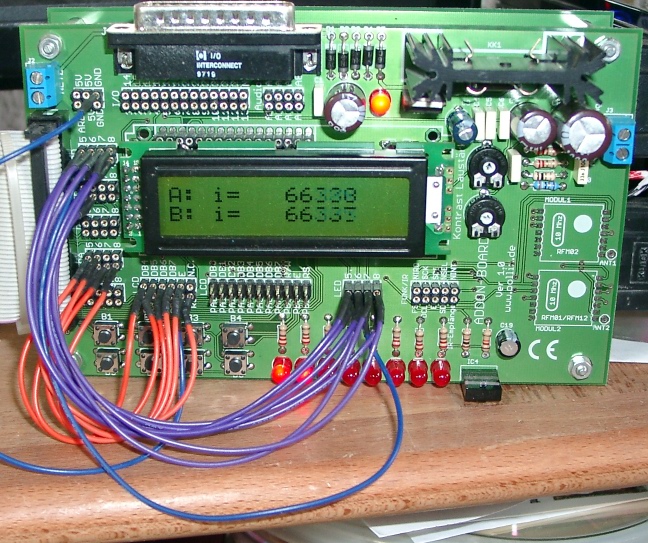
Hier noch ein Bild dazu.

Die Ausgabe auf Port D ist übrigens überflüssig und macht nur
etwas gemütliche rote Beleuchtung am Schreibtisch.
Hallo Klaus,

wohin genau gehören die Dateien

- lcd-routines.h
- lcd-routines.c

die lcd-routines.h habe ich in das Verzeichniss vom Kompiler und die
lcd-routines.c in das Projektverzeichniss gelegt. Leider bekomme
Fehlermeldungen:

Build started 19.7.2009 at 17:16:26
avr-gcc -mmcu=atmega16 -Wl,-Map=LCD-Test.map LCD-Test.o     -o
LCD-Test.elf
LCD-Test.o: In function `main':
D:\Daten
Notebook\Uni\Diplomarbeit\AVR\LCD-Test\default/../LCD-Test.c:11:
undefined reference to `lcd_init'
D:\Daten
Notebook\Uni\Diplomarbeit\AVR\LCD-Test\default/../LCD-Test.c:13:
undefined reference to `lcd_data'
D:\Daten
Notebook\Uni\Diplomarbeit\AVR\LCD-Test\default/../LCD-Test.c:14:
undefined reference to `lcd_data'
D:\Daten
Notebook\Uni\Diplomarbeit\AVR\LCD-Test\default/../LCD-Test.c:15:
undefined reference to `lcd_data'
D:\Daten
Notebook\Uni\Diplomarbeit\AVR\LCD-Test\default/../LCD-Test.c:16:
undefined reference to `lcd_data'
D:\Daten
Notebook\Uni\Diplomarbeit\AVR\LCD-Test\default/../LCD-Test.c:18:
undefined reference to `set_cursor'
D:\Daten
Notebook\Uni\Diplomarbeit\AVR\LCD-Test\default/../LCD-Test.c:20:
undefined reference to `lcd_string'
make: *** [LCD-Test.elf] Error 1
Build failed with 7 errors and 0 warnings...


Wie kann ich das in Ordnung bringen?
Ich nehme nicht das AVR-Studio, sondern mache immer alles in der
Kommandozeile; da habe ich diese Dateien in einem Verzeichnis.

Du wirst dem AVR-Studio noch sagen müssen, daß lcd-routines.c
mit zum Projekt gehört.

Das müsste im Source-Tree links gehen mit Rechtsklick auf
"Source Files", darin auswählen "Add existing source file(s)"
und dann die lcd-routines.c auswählen.
Bitte melde dich an um einen Beitrag zu schreiben. Anmeldung ist kostenlos und dauert nur eine Minute.
Bestehender Account
Schon ein Account bei Google/GoogleMail? Keine Anmeldung erforderlich!
Mit Google-Account einloggen
Mit Google-Account einloggen
Noch kein Account? Hier anmelden.