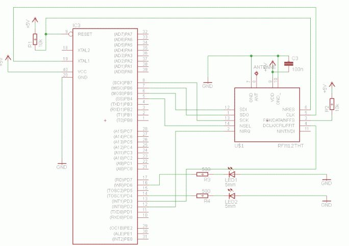
Hallo Forum,

nachdem ich jetz das ganze Wochenende am Fehlersuchen war wende ich mich
hoffnungsvoll an euch.

Problem: Den angehängten Code habe ich an einem Mega48 am laufen und der
funktioniert auch wunderbar, jetzt will ich das auf den inzwischen
gelieferten AT Mega162 portieren und dort will es einfach nicht
funktionieren.

Die MAIN LOOP Kontroll LED und die UART Ausgabe machen was sie sollen,
die Interrupt LED ist immer aus und die Kommunikation mit dem RFM läuft
irgendwie gar nicht.

Das RFM-Modul wird anscheinend nicht initialisiert weil am Tacktausgang
stehen 1MHz an obwohl es 10MHz nach der Initialisierung sein sollten,
deshalb hängt jetzt ein extra Quarz am AT Mega

Verdrahtungsfehler würde ich ausschliessen, ich hab das inzwischen
gefühlte 100 mal auf dem Steckbrett gesteckt und das Ergebnis ist immer
das gleiche.
M48 geht sofort M162 geht nicht.

Fehler im Datenblatt des M162 glaub ich auch nicht weil über die SPI
schnittstelle ist ja auch der Programmer angeschlossen.


Ich hoffe Ihr habt noch vorschläge wo ichh suchen könnte.
Angehängte Dateien:
-

M162_RFM.GIF
28 KB
Hat keiner eine Idee?

hier ist nochmal der Code zum direkt ansehen und der Schaltplan.

Ich bin hier echt am Verzweifeln, das muss doch gehen...

AchJa: der Code ist von www.technofun.org und funktioniert auf dem
Mega48 super.
1 | $regfile = "m162def.dat" |
2 | '$regfile = "m48def.dat" |
3 | $hwstack = 60 |
4 | $swstack = 60 |
5 | $framesize = 60 |
6 | |
7 | $crystal = 9830400 |
8 | $baud = 38400 |
9 | Baud = 38400 |
10 | |
11 | |
12 | |
13 | '###################################################### |
14 | 'Settings for RFM12 |
15 | |
16 | 'word for SPI Tx |
17 | Dim Spi_tx_wrd As Word |
18 | Dim Spi_tx_l As Byte At Spi_tx_wrd Overlay |
19 | Dim Spi_tx_h As Byte At Spi_tx_wrd + 1 Overlay |
20 | |
21 | 'word for SPI Rx |
22 | Dim Spi_rx_wrd As Word |
23 | Dim Spi_rx_l As Byte At Spi_rx_wrd Overlay |
24 | Dim Spi_rx_h As Byte At Spi_rx_wrd + 1 Overlay |
25 | |
26 | Dim Rxindex As Byte |
27 | Dim I As Byte |
28 | |
29 | Dim Rxbuf(31) As Byte |
30 | Dim Rxmsg As String * 28 At Rxbuf(1) Overlay |
31 | |
32 | Dim Rxmsgflg As Bit |
33 | |
34 | '**** Change Alias's to match your hardware. **** |
35 | 'AT Mega 162 |
36 | Rfm12_cs Alias Portb.4 |
37 | Config Rfm12_cs = Output |
38 | Set Rfm12_cs |
39 | |
40 | Rfm12_sdi Alias Portb.5 |
41 | Config Rfm12_sdi = Output |
42 | |
43 | Rfm12_sdo Alias Pinb.6 |
44 | Config Rfm12_sdo = Input |
45 | Set Portb.6 |
46 | |
47 | Rfm12_sck Alias Portb.7 |
48 | Config Rfm12_sck = Output |
49 | |
50 | 'AT Mega 48 |
51 | 'Rfm12_cs Alias Portb.2 |
52 | 'Config Rfm12_cs = Output |
53 | 'Set Rfm12_cs |
54 | |
55 | 'Rfm12_sdi Alias Portb.3 |
56 | 'Config Rfm12_sdi = Output |
57 | |
58 | 'Rfm12_sdo Alias Pinb.4 |
59 | 'Config Rfm12_sdo = Input |
60 | 'Set Portb.4 |
61 | |
62 | 'Rfm12_sck Alias Portb.5 |
63 | 'Config Rfm12_sck = Output |
64 | |
65 | Config Int0 = Falling |
66 | On Int0 Isr_int0 |
67 | Enable Int0 |
68 | '###################################################### |
69 | |
70 | 'Kontroll LED |
71 | Led Alias Portd.6 |
72 | Config Pind.6 = Output |
73 | |
74 | Led2 Alias Portd.4 |
75 | Config Pind.4 = Output |
76 | |
77 | '###################################################### |
78 | |
79 | |
80 | 'config SPI for RFM12 |
81 | 'Config Spi = Soft , Din = Pinb.6 , Dout = Portb.5 , Ss = Portb.4 , Clock = Portb.7 , Spiin = 0 |
82 | Config Spi = Hard , Interrupt = Off , Data Order = Msb , Master = Yes , Polarity = Low , Phase = 0 , Clockrate = 64 |
83 | Spiinit |
84 | '###################################################### |
85 | |
86 | |
87 | 'Los gehts |
88 | Gosub Rfm12_init |
89 | Gosub Rfm12_restart_synchron |
90 | |
91 | Enable Interrupts |
92 | Spi_tx_wrd = 0 |
93 | Gosub Rfm12_spi_wrt |
94 | |
95 | |
96 | |
97 | '###################################################### |
98 | '### Hauptschleife ### |
99 | '###################################################### |
100 | |
101 | Do |
102 | 'If A Message Is Ready Then Print It Out. |
103 | If Rxmsgflg = 1 Then |
104 | Rxmsgflg = 0 |
105 | Print Rxmsg |
106 | Rxmsg = "" |
107 | End If |
108 | |
109 | |
110 | 'Toggle Led |
111 | Waitms 200 |
112 | Toggle Led2 |
113 | Waitms 200 |
114 | Toggle Led2 |
115 | Waitms 800 |
116 | Toggle Led2 |
117 | Waitms 300 |
118 | Toggle Led2 |
119 | Print "hallo welt" |
120 | Print Bin(spcr) |
121 | Print Bin(ddrb) |
122 | Print Bin(ddrd) |
123 | |
124 | 'any user code can be added here. |
125 | Loop |
126 | |
127 | |
128 | |
129 | '###################################################### |
130 | '### ISR und Subs ### |
131 | '###################################################### |
132 | |
133 | Isr_int0: |
134 | Toggle Led 'Kontroll LED ein während empfang |
135 | Spi_tx_wrd = 0 'get status word from RFM12. |
136 | Gosub Rfm12_spi_wrt |
137 | If Spi_rx_wrd.15 = 1 Then 'check FFIT bit in status word. |
138 | Spi_tx_wrd = &HB000 'get Rx byte. will be in SPI_Rx_L |
139 | Gosub Rfm12_spi_wrt |
140 | |
141 | If Rxindex < 28 Then Incr Rxindex 'save byte in RxBuf() , don't over run array bounds. |
142 | Rxbuf(rxindex) = Spi_rx_l |
143 | |
144 | If Spi_rx_l = 0 Then 'if last byte is 0 (null).message is ready |
145 | Rxindex = 0 |
146 | Rxmsgflg = 1 'set message ready flg. |
147 | Gosub Rfm12_restart_synchron |
148 | End If |
149 | Else 'for any other interrupt just print the status word for now. |
150 | Print Hex(spi_rx_wrd) |
151 | End If |
152 | Toggle Led 'Kontroll LED aus nach empfang |
153 | Return |
154 | |
155 | Rfm12_spi_wrt: 'Send word (SPI_Tx_wrd) to RFM12.Also receive word (SPI_Rx_wrd). |
156 | Reset Rfm12_cs 'RFM12 Chip select |
157 | Spi_rx_h = Spimove(spi_tx_h) 'send hi byte. |
158 | Spi_rx_l = Spimove(spi_tx_l) 'send lo byte. |
159 | Set Rfm12_cs 'deselect chip. |
160 | Return |
161 | |
162 | Rfm12_restart_synchron: |
163 | Spi_tx_wrd = &HCA81 |
164 | Gosub Rfm12_spi_wrt |
165 | Spi_tx_wrd = &HCA83 |
166 | Gosub Rfm12_spi_wrt |
167 | Return |
168 | |
169 | Rfm12_init: 'Initialize RFM12 |
170 | Restore Init_data |
171 | For I = 1 To 11 |
172 | Read Spi_tx_wrd |
173 | Gosub Rfm12_spi_wrt 'send init data to RFM12. |
174 | Waitms 30 |
175 | Next |
176 | Return |
177 | |
178 | Init_data: |
179 | Data &HC0E0% 'ClockDiv/Battlow. |
180 | Data &H80D7% '433mhz band,Enable Tx reg.,Enable Rx FIFO |
181 | Data &H82D8% 'Enable Rx, crystal osc., Synth. |
182 | Data &HA620% '435mhZ |
183 | Data &HC610% '19kbps |
184 | Data &H9184% 'Rx settings. |
185 | Data &HCED4% 'synchron pattern = D4 'AFC settings. |
186 | Data &HC4A7%. 'AFC settings. |
187 | Data &H9850% 'Tx 90khz deviation. |
188 | Data &HCC17% 'PLL settings. |
189 | Data &HC2ED% 'Data Filter settings. |
Bitte melde dich an um einen Beitrag zu schreiben. Anmeldung ist kostenlos und dauert nur eine Minute.
Bestehender Account
Schon ein Account bei Google/GoogleMail? Keine Anmeldung erforderlich!
Mit Google-Account einloggen
Mit Google-Account einloggen
Noch kein Account? Hier anmelden.