Hi,

Ich hab heute ein Display von Pollin bekommen. (TC1602E)

Dann hab ich das ganze ans Pollin EvolutionsBoard 2.0 mit einem Atmega
16 drauf angeschlossen. Kabelbelegung stimmt definitiv hab ich nun schon
wtliche male überprüft.

Wenn der µc angeschaltet wird initalisiert sich das Display und das
wars. Ich habe folgenden code verwendet:

$regfile = "m16def.dat"
$crystal = 16000000

Ddra = &B11111111
Porta = &B00000000

Config Lcdpin = Pin , Db4 = Porta.0 , Db5 = Porta.1 , Db6 = Porta.2 ,
Db7 = Porta.3 , Rs = Porta.4 , E = Porta.5
Config Lcd = 16 * 2
Config Lcdbus = 4

Initlcd
Cls
Cursor Off
Locate 1 , 1
Lcd "Hello World"

Do
 nop
Loop

End

Kann mir jemand sagen wo das Problem liegt ? Andere Programmiersprachen
als Bascom behersche ich monetan leider nicht. Wenn mir aber jemand bei
C helfen könnte falls das die Einzigste Lösung sein sollte, währe ich
sehr dankbar.

mfg Olliver
Hast Du den Pin AVCC an +Ub liegen? Der Port A wird über AVCC mit "Saft"
versorgt.

MfG Paul
Auf den MC. Das Display hat sicher keinen AVCC-Anschluss. ;-)

MfG Paul
Das ist das Datenblatt von dem Board auf dem der µC sitzt:

http://www.pollin.de/shop/downloads/D810046B.PDF
Hi

Woher weisst du eigentlich, daß das Display initialisiert wird.

MfG Spess
Wenn ich das Display an die Versorgungsspannung anschließe, erscheinen
auf der 1. display zeile schwarze Vierecke. Wenn ich nun den µc
anschalte verschwinden diese.
Hi kann mir mal pls jemand Hilfe zum Takt vom mega16 geben ?

Wenn ich kein externes quartz angeschlossen habe, auf was kann ich ihn
dann takten ? Un wenn ich das externe verwende welche fuse bits müssen
dann bei pony prog gesetzt werden ?
Von "Natur aus" ist der interne Oszillator eingestellt und der taktet
mit 1MHz (sagt das Datenblatt). Ebenda steht ab Seite 23, wie man die
Fuses für den Takt setzen muß, wenn man "draußen dran" einen Quarz hat.

MfG Paul
So hab die ganze Verkabelubng nochmal neu gemacht und alles auf PortB
gelegt.

Wieder der Selbe Effekt. Dann hab ich nochmal mit einer Led die
einzelnen Pins am Display abgetastet beim einschalten.

An den Pins DB4 - 7 flackert die Led 2 mal schnel hintereinander auf und
bleibt dann an.
Moin,

=>Olliver

Prüfe erst einmal, ob das JTag-Interface aktiviert ist. Wenn ja, dann
deaktiviere es.
Viel Erfolg
Stefan
Also ich die fuses vom µc bisher noch nicht geändert.

Wenn mir jemand helfen könnte diese richtig zu konfigurieren währe ich
euch super dankbar.

Nicht das ihr denkt ich hätte nicht ins Datenblatt vom µc geschaut ;)

Nur durch die über 300 Seiten bin ich dann doch nicht wirkluch
durchgestiegen.
Hallo,

das ist Dein Problem: "Du hast nichts geändert"!!!
Die JTAGEN-Sicherung (Fuse) ist im Auslieferungszustand gesetzt!
Siehe Handbuch Seite 260.
Viel Erfolg
Stefan
Hi!
Das klingt so als wäre RS nicht angeschlossen,fehlerhaft oder wird nicht
zugeschaltet.

Viel Erfolg, Uwe
Angehängte Dateien:
-

lcd_pot.jpg
23 KB
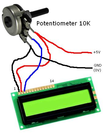
Try the code below. See the attached picture
for the contrast adjustment potentiometer.

The LCD is connected to the PortA of the ATmega16.
The code was tested with real hardware. (STK500 + ATmega16 + 2*16 LCD)
1 | $regfile = "m16def.dat" |
2 | $crystal = 16000000 |
3 | |
4 | $hwstack = 32 |
5 | $swstack = 16 |
6 | $framesize = 40 |
7 | |
8 | ' LCD Pins: AVR Pins |
9 | ' ================================ |
10 | ' DB7 : PORTA.7 |
11 | ' DB6 : PORTA.6 |
12 | ' DB5 : PORTA.5 |
13 | ' DB4 : PORTA.4 |
14 | ' E : PORTA.3 |
15 | ' RS : PORTA.2 |
16 | '
|
17 | ' Connect the R/W LCD pin permanently to GND with a wire. |
18 | |
19 | Config Lcdpin = Pin,Db4=PortA.4,Db5=PortA.5,Db6=PortA.6,Db7=PortA.7,E=PortA.3,Rs=PortA.2 |
20 | Config Lcd = 16 * 2 |
21 | |
22 | Dim OneByte As Byte |
23 | |
24 | Cursor Off Noblink |
25 | Cls
|
26 | Waitms 100 |
27 | |
28 | Locate 1 , 1 |
29 | Lcd "Hello World!" |
30 | |
31 | Locate 2 , 1 |
32 | Lcd "Counter: " |
33 | |
34 | Do
|
35 | Locate 2 , 9 |
36 | Lcd OneByte ; " " |
37 | Waitms 500 |
38 | Incr OneByte |
39 | Loop
|
40 | |
41 | End
|
Angehängte Dateien:
-

DSC00098.JPG
480 KB
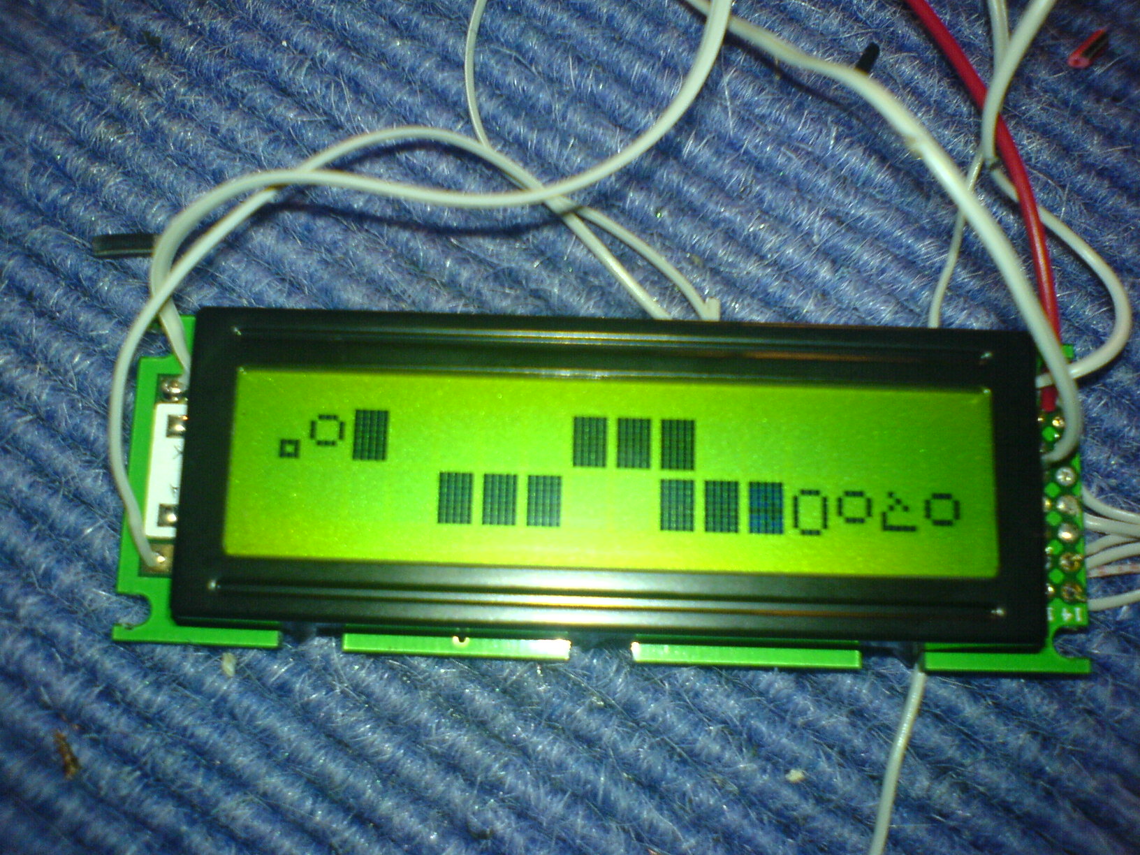
So leuts jetzt fängt es an lustig zu werden.

Hab ja um zu sehen ob was gesendet wird eine LED von - µC Board zu auf
den jeweiligen Pin gehalten. Dann bin ich auf die Idee gekommen mal die
Reset Taste zu drücken, während ich das Kabel noch am Pin hatte.

Folgendes ist passiert:

Siehe Bild ;)

Was kann ich nun daraus schließen ?
The controller chip on LCD module must be compatible
with the Hitachi HD44780 controller chip.

"INITLCD" is not necessary because Bascom AVR will call it
automatically at start up if LCD commands are used in the
program. (Like CLS, LCD, ..)."INITLCD" is used to
reinitialize the LCD at runtime in case you power down
the LCD and then power it up again.(e.g., to save batteries).
You can try to add "INITLCD" before "Cursor Off Noblink"
but I don't think that this will fix your problem.


What you can do:

==============================================

Option 1:

Check again your hardware and all the used
connections.

Is the the R/W pin of the LCD permanently
connected to GND?

==============================================

Option 2:

Buy an LCD compatible with the Hitachi
HD44780 chip.

Note that Bascom AVR also support the LCD controller
KS077 and the LCD controller used by the EA-DOG LCD
modules. See Bascom help file "CONFIG LCD".
==============================================

Option 3:

Keep your LCD.

(You will need the full version of Bascom AVR).

Download the datasheet of the controller chip
used by your LCD module.

Instead of using "Config Lcdpin" use the Bascom
library lcd4.lib. You will have to modify the
Bascom library lcd4.lib to suit the needs of the
used LCD controller chip. Note that in this case
"Config Lcdpin" is not used because the used pins
are defined in the library lcd4.lib. Remember to
put $lib "lcd4.lib" at the beginning of your
program. The Bascom libraries are written in
assembly but the code in the lcd4.lib is very
simple to modify and to understand. It might be
that you only need to modify the fixed delays
used in the library. (This library does not use
the busy flag of the LCD so the R/W pin of the
LCD must be permanently connected to GND).
If you try to modify lcd4.lib, make sure you make
a copy of the original file before you modify it.

==============================================
Angehängte Dateien:
-

DSC00099.JPG
350 KB
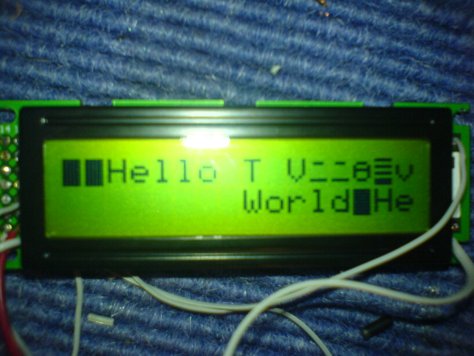
Kann mir jemand erklären wie genau ich eine Lib umsetzen kann, die auch
die Busy Flags auswertet ?

Was würden denn passieren wenn die Busy Flags ausgewertet werden und die
Quartzangabe nicht stimmt ? Kann es dann immernoch zu Taktfehlern kommen
?

Hoffe auf eure Hilfe.

Edit. Auf dem Display seinen auch die Infos die übertragen werden sollen
anzukommen, wenn ich eine Led von Masse auf Displaypin lege und den
Resettaster drücke:

(Bild siehe Anhang)
See the Bascom AVR library "lcd4busy.lib" which is
located in the folder LIB.

Do you have the full version of Bascom AVR?
(The source code of the LIB files in not included with the demo
version).

Which Bascom version are you using?
Bitte melde dich an um einen Beitrag zu schreiben. Anmeldung ist kostenlos und dauert nur eine Minute.
Bestehender Account
Schon ein Account bei Google/GoogleMail? Keine Anmeldung erforderlich!
Mit Google-Account einloggen
Mit Google-Account einloggen
Noch kein Account? Hier anmelden.