IRMP auf STM32 - ein USB IR Empfänger/Sender/Einschalter mit Wakeup-Timer
Ein IR Fernbedienungsempfänger mit vielen Funktionen auf Basis preiswerter Hardware.
Copyright (C) 2014-2018 Jörg Riechardt
Einleitung
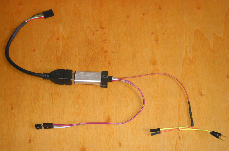
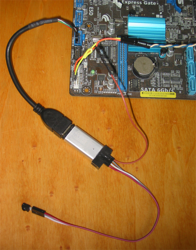
Für ca. 4 - 8 € kann man auf ebay einen ST-Link Emulator oder ein STM32F103 Board kaufen, meistens in China hergestellt. Auf den darauf befindlichen STM32F103 Mikrocontroller wird eine Open Source Firmware mit vielen Funktionen geflasht.
Funktionen
- Anschluss über USB
- meldet sich als HID Device an, kein Treiber nötig, erscheint als „HID konformes Gerät“ oder /dev/hidraw
- überträgt die Daten per USB2 in Hardware mit Fullspeed
- IR Empfänger (ca. 40 Protokolle werden in HW dekodiert)
- PC mit Fernbedienung Einschalten aus S3 (STR) und S4 (STD) über USB oder aus S3, S4 und S5 (SoftOff) über Motherboard-Power-Schalter (+5V oder +3,3V nötig, auf USB oder vom Netzteil/Motherboard zugeführt)
- PC mit eingebautem Timer Einschalten aus S3 (STR) und S4 (STD) über USB oder aus S3, S4 und S5 (SoftOff) über Motherboard-Power-Schalter (+5V oder +3,3V nötig, auf USB oder vom Netzteil/Motherboard zugeführt)
- PC mit Fernbedienung Resetten über Motherboard-Reset-Schalter
- IR Sender (ca. 40 Protokolle)
- die Konfiguration wird im emulierten Eeprom gespeichert
- im Rahmen der Größe des Eeproms beliebig viele Makros mit beliebiger Tiefe und beliebig viele Wakeups: MACRO_SLOTS x (MACRO_DEPTH + 1) + WAKE_SLOTS < 85 bei F103, < 170 bei F105
- Bootloader für bequemes Firmware Update
Ein Makro ermöglicht das Senden einer Befehlssequenz über die IR-Sendediode bei Empfang eines Tastendrucks.
macroslot0 ist der Auslöser, macroslot1 … macroslot7 die Befehle, die bei Empfang des Auslösers ausgesendet werden.
Software Linux
- GUI Konfig-Tool stm32IRconfig_gui für die Konfiguration: Wakeup Code, Makros, Alarmzeit setzen, auslesen und zurücksetzen, IR senden und Anzeigen der empfangenen IR Codes. Wakeups und Makros können auch per Fernbedienung progammiert werden. Erstellen der Übersetzungstabelle mit Fernbedienung und Maus, sowie testen und bearbeiten. Detaillierte Ausgaben zur Analyse.
- Kommandozeilenprogramm stm32IRconfig für die Konfiguration: Wakeup Code, Makros, Alarmzeit setzen, auslesen und zurücksetzen, IR senden und Anzeigen der empfangenen IR Codes. Wakeups und Makros können auch per Fernbedienung progammiert werden.
- stm32IRalarm zum Alarmzeit setzen und auslesen per Skript
- irmplircd ist ein Daemon, der im Hintergrund als eigenständiger lirc Server läuft und die IR Codes/events an die Anwendung weitergibt https://github.com/realglotzi/irmplircd
- irctl für die Konfiguration: https://github.com/olebowle/irctl
- Fertige Software für LibreELEC, Ubuntu, yaVDR, easyVDR, MLD, OpenELEC.
Software Windows
- GUI Konfig-Tool stm32IRconfig_gui (wie Linux)
- Kommandozeilenprogramm stm32IRconfig (wie Linux)
- stm32IRalarm zum Alarmzeit setzen und auslesen per Skript
- MediaPortal Plugin: https://github.com/pikim/HIDIRT-host/tree/master/hidirt.MePo
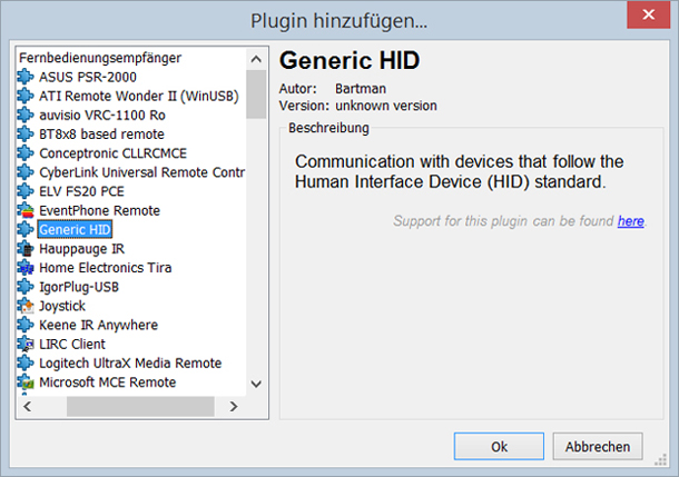
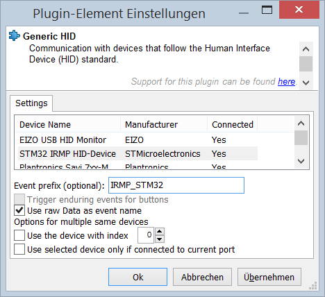
- EventGhost mit Generic HID
Keymap aufbauen
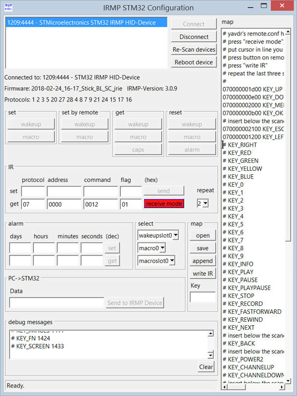
Mit der stm32IRconfig_gui kann man die Keymap mit der Fernbedienung aufzubauen. Es gibt zwei Methoden.
Erste Methode: "receive mode" drücken und die Muster Keymap öffnen.
Zeile mit Tastenname anklicken, Taste auf der Fernbedienung drücken, "write IR" drücken - dies für alle Tasten wiederholen.
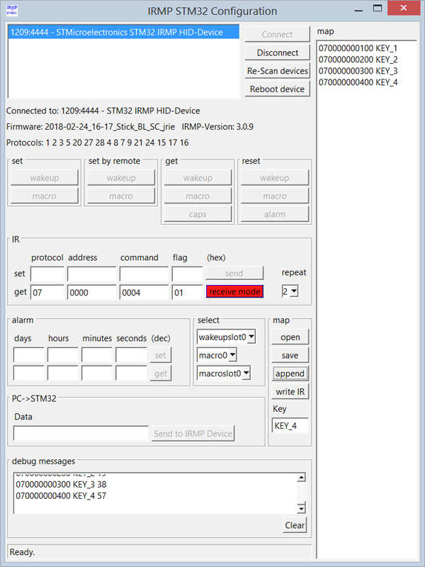
Zweite Methode: "receive mode" drücken.
Taste auf der Fernbedienung drücken, Namen der Taste ins Textfeld Key eingeben und "append" drücken - dies für alle Tasten wiederholen.
Man kann die Keymap gleich testen: Nach Druck auf die Fernbedienungstaste sollte der rote Cursor in der entsprechenden Zeile stehen.
Am Ende save drücken und die Keymap speichern.
Wakeup anlernen
set by remote - wakeup drücken, Fernbedienungstaste drücken, fertig.
Eventghost
.
.
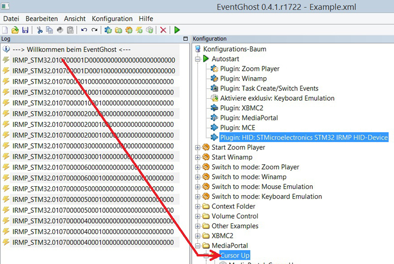
Ein Tastencode im linken Event-Fenster kann per Drag&Drop nach rechts ins Konfigurations-Fenster gezogen und der gewünschten Aktion eines der Plugins zugeordnet werden.
Download
https://github.com/j1rie/IRMP_STM32
Die Quellen sind erst nach dem Durchlauf des prepare Skripts vollständig, das Skript lädt ST- und IRMP-Quellen herunter, packt sie aus und patcht sie.
Das hat den Vorteil, dass die Patche unter GPL gestellt werden können, ohne den Original Lizenzen in die Quere zu kommen.
Man sieht auch besser, was geändert wurde.
Pinbelegung
IR Sendediode - PB6
Logging - PB10 = Tx, verbinden mit Rx vom USB-seriell-TTL
F103 Developer Board:
IR TSOP - PB11
Einschalter Motherboard - PB14 und über USB
Toggle LED - PB13
Wakeup reset - PB12
Reset - PB15
F105:
IR TSOP - PC6
Einschalter Motherboard - PB7 und über USB
Toggle LED - PB12
Reset - PB8
Andere Boards:
https://github.com/j1rie/IRMP_STM32/blob/master/STM32F103/src/config.h
Firmware kompilieren
Linux: mit arm-none-eabi-gcc
Windows: mit Coocox CoIDE (benutzt auch arm-none-eabi-gcc)
http://www.olliw.eu/2013/stm32-this-and-that/#coocoxinstall
Firmware flashen
Firmware Flashen mit USB-seriell-TTL (STM32F103):
Ground und 5V bzw. 3,3V verbinden, Rx an Tx , Tx an Rx
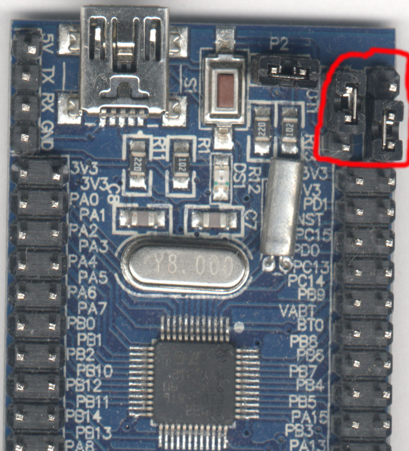
BOOT0 Jumper auf 3,3V (Vorsicht, auf manchen Boards ist BOOT0 fälschlich mit BOOT1 beschriftet, Position siehe Fotos), Reset
./stm32flash -v -w /Pfad/firmware.bin /dev/ttyUSB0
BOOT0 wieder auf Ground, Reset, USB neu anschliessen (oder USB Jumper ab, an)
Firmware Flashen über USB (STM32F105):
BOOT0 Jumper auf 3,3V, Reset, USB neu anschliessen (oder USBDP kurz auf low)
./dfu-util -a 0 -s 0x8000000 -D /Pfad/firmware.bin
BOOT0 wieder auf Ground, Reset, USB neu anschliessen (oder USBDP kurz auf low)
Firmware Flashen mit ST-Link:
Programmer SWDIO -> Ziel PA13/TMS , Programmer SWCLK -> Ziel PA14/TCK , Gnd - Gnd, 3,3V – 3,3V
Firmware Flashen über USB bei vorhandenem Bootloader:
./FlashDFUxxx.sh /Pfad/newFirmware.bin
dann das Board anschliessen.
andere STM32 Mikrocontroller
- die STM32F103 Firmware ist einfach anpassbar an STM32L1xx und STM32F3xx, da dieselbe USB Library genutzt wird
- die STM32F105 Firmware ist einfach anpassbar an STM32F107, STM32F2xx und STM32F4xx, da dieselbe USB Library genutzt wird
Fotos von den Anfängen
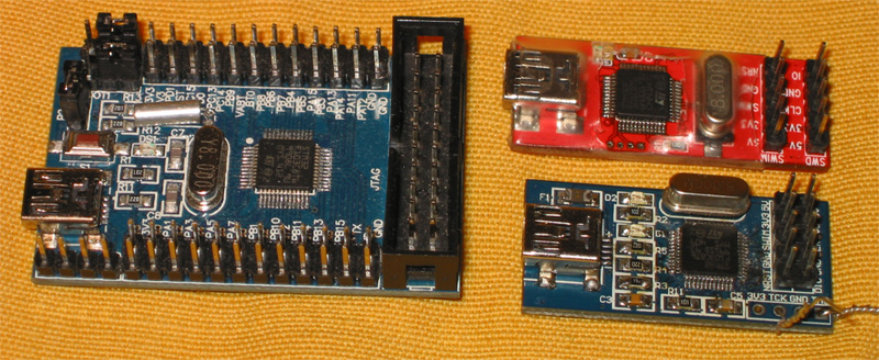
Auf dem STM32F103C8T6 Entwickler Board sind BOOT0 und BOOT1 vertauscht beschriftet.
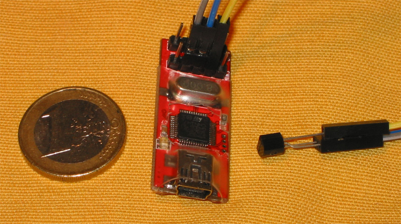
Auf dem roten ST-Link Emulator ist das Plastik etwas aufgeschnitten.
Auf dem blauen ST-Link Emulator sind CLK und TCK sowie DIO und TMS vertauscht.
Am Roten eine TSOP „Attrappe“ und 1 € zum Größenvergleich.
An den St-Links muss eventuell der PullUp Widerstand (Roter) bzw. PullDown Widerstand (Blauer) an SWIM entfernt werden. Oder man wählt eine Funktion, die dadurch nicht gestört wird.
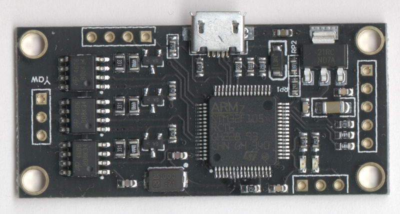
Mit diesem STM32F105 Board, das ursprünglich für die Kamera-Aufhängungs-Ansteuerung gedacht war, fing die Entwicklung an.
Jumper Position für Flashen über Tx/Rx (auch wenn die Beschriftung vertauscht ist)
Danke an
Frank Meyer für IRMP und IRSND. [1]
Uwe Becker für das Anpassen von IRMP und IRSND an den STM32F4xx
und seinen USB-HID für den STM32F4xx. [2]
Seine Arbeit war hilfreich, um mit dem STM32F105 anfangen zu können.
Andrew Kambaroff für seinen USB-HID für den STM32F103. [3]
Seine Arbeit war hilfreich, um mit dem STM32F103 anfangen zu können.
Ole Ernst für Code Review, Linux Makefile und Linux Download-Auspack-Patch-Skript, viel bessere Makro Implementierung und neues Protokoll. [4]
Manuel Reimer für gcc-4.9 Fix, SimpleCircuit und Prüfung ob Host läuft. [5]
[1] https://www.mikrocontroller.net/articles/IRMP
[2] http://mikrocontroller.bplaced.net/wordpress/?page_id=744
[3] http://sysmagazine.com/posts/208026/
[4] https://github.com/olebowle
[5] https://github.com/M-Reimer
Diskussion
Fragen, Kommentare, Verbesserungsvorschläge, Kritik und Ähnliches kann im https://www.vdr-portal.de/forum/index.php?thread/123572-irmp-auf-stm32-ein-usb-ir-empf%C3%A4nger-sender-einschalter-mit-wakeup-timer/ geäussert werden.
https://www.mikrocontroller.net/topic/347290 scheint eingeschlafen zu sein.
Bauanleitung
https://www.mikrocontroller.net/articles/IRMP_auf_STM32_%E2%80%93_stark_vereinfachte_Bauanleitung
https://www.mikrocontroller.net/articles/IRMP_auf_STM32_-_Bauanleitung
Viel Spaß mit IRMP auf STM32!
IRMP on STM32 - a USB IR receiver/sender/powerswitch with wakeup-timer
A remote control receiver with many functions based on cheap hardware.
Introduction
For 4 - 8 € you can buy on ebay a ST-Link emulator or a STM32F103 development board, manufactured in China usually. Onto the STM32F103 mikrocontroller on it an open source firmware with many functions will be flashed.
Functions
- connection via USB
- registers as HID device, no driver needed, appears as /dev/hidraw or "Custom HID device"
- transfers the data via USB2 in hardware with fullspeed
- IR receiver (ca. 40 protocols decoded in hardware)
- switch PC on via remote control from S3 (STR) and S4 (STD) via USB or from S3, S4 and S5 (SoftOff) via motherboard-switch (+5V needed, on USB or from PSU or motherboard)
- switch PC on via build in timer from S3 (STR) and S4 (STD) via USB or from S3, S4 and S5 (SoftOff) via motherboard-switch (+5V needed, on USB or from PSU or motherboard)
- reset PC with remote control via motherboard-reset-switch
- IR sender (ca. 40 protocols)
- the configuration is stored in the emulated eeprom
- within eeprom size any number of macros with any depth and any number of wakeups: MACRO_SLOTS x (MACRO_DEPTH + 1) + WAKE_SLOTS < 85 for F103, < 170 for F105
- bootloader for comfortable firmware update
A macro enables sending a sequence of commands via the IR-senddiode on reception of a keypress.
macroslot0 is the trigger, macroslot1 … macroslot7 are the commands, to be send on reception of the trigger.
Software Linux
- GUI config-tool stm32IRconfig_gui for configuration: set, get and reset wakeup codes, macros, alarm time, send IR and show the received IR code. It is possible to program wakeups and macros via remote control. Create the translation table with remote control and mouse, as well test and edit. Comprehensive debug messages.
- command line program stm32IRconfig for configuration: set, get and reset wakeup code, macros, alarm time, send IR and show the received IR code. It is possible to program wakeups and macros via remote control.
- stm32IRalarm for setting and reading alarm time via script
- irmplircd is a daemon, running in background as an independent lirc server and passing the IR codes/events on to the application https://github.com/realglotzi/irmplircd
- irctl for configuration: https://github.com/olebowle/irctl
- Software ready for LibreELEC, Ubuntu, yaVDR, easyVDR, MLD, OpenELEC.
Software Windows
- GUI config-tool stm32IRconfig_gui (same as linux)
- command line programm stm32IRconfig (same as linux)
- stm32IRalarm for setting and reading alarm time via script
- MediaPortal plugin: https://github.com/pikim/HIDIRT-host/tree/master/hidirt.MePo
- EventGhost with Generic HID
Creating a keymap
The stm32IRconfig_gui can be used for building a keymap with the remote control. There are two methods.
First method: Press "receive mode" and open the template keymap.
Click the line with the button's name, press the button on the remote, press "write IR" - repeat this for all buttons.
Second method: Press "receive mode".
Press the button on the remote, enter the button's name into the textfield Key and press "append" - repeat this for all buttons.
You can test the keymap immediately: After pressing the button on the remote, the red cursor should be in the coresponding line.
At the end press "save" and save the keymap.
Lerning wakeup
press set by remote - wakeup, press button on remote control, finished.
Eventghost
.
.
A keycode in the left event-window is pulled via drag&drop into the right configuration-window and assigned to the wanted action of a plugin.
Download
https://github.com/j1rie/IRMP_STM32
The sources are complete only after running the prepare script, the script downloads the ST- and IRMP-sources, extracts and patches them.
This makes it possible to put the patches under GPL, without interfering with the original licences.
It is easier to see, what has been changed, too.
Pin-Out
IR send diode - PB6
logging - PB10 = Tx, connect to Rx of USB-serial-TTL
F103 Developer Board:
IR TSOP – PB11
power on switch motherboard - PB14 and via USB
toggle LED - PB13
Wakeup reset - PB12
Reset - PB15
F105:
IR TSOP - PC6
power on switch motherboard - PB7 and via USB
toggle LED - PB12
Reset - PB8
Other boards:
https://github.com/j1rie/IRMP_STM32/blob/master/STM32F103/src/config.h
Firmware Compilation
Linux: arm-none-eabi-gcc
Windows: Coocox CoIDE (uses arm-none-eabi-gcc too)
http://www.olliw.eu/2013/stm32-this-and-that/#coocoxinstall
Firmware Flashing
flash firmware with USB-serial-TTL (STM32F103):
connect ground and 5V resp. 3,3V, Rx - Tx , Tx - Rx
BOOT0 jumper on 3,3V, (caution, on some boards BOOT0 is labeled wrongly as BOOT1, see images for position), reset
./stm32flash -v -w /path/firmware.bin /dev/ttyUSB0
BOOT0 back to ground, reset, reconnect USB (or USB jumper off, on)
flash firmware via USB (STM32F105):
BOOT0 jumper on 3,3V, reset, reconnect USB (or USBDP low shortly)
./dfu-util -a 0 -s 0x8000000 -D /path/firmware.bin
BOOT0 back to ground, reset, reconnect USB (or USBDP low shortly)
flash firmware via ST-Link:
SWDIO -> PA13, SWCLK -> PA14, Gnd - Gnd, 3,3V - 3,3V
flash firmware via USB if bootloader present:
./FlashDFUxxx.sh /Pfad/newFirmware.bin
then connect the board.
Other STM32 Microcontrollers
- the STM32F105 firmware is easily customizable to STM32F107, STM32F2xx and STM32F4xx, as the same USB library is used
- the STM32F103 firmware is easily customizable to STM32L1xx and STM32F3xx, as the same USB library is used
Images from the beginnings
On the STM32F103C8T6 developer board BOOT0 and BOOT1 labels are exchanged. On the red ST-Link emulator the plastic is cut open some. On the blue ST-Link emulator CLK and TCK are exchanged and DIO und TMS as well.
Attached to the red a TSOP „dummy“ and 1 € for size comparison.
On the St-Links it might be necessary to remove the pullup resistor (red) or the pulldown resistor (blue) on SWIM. Or use a function, which is not disturbed by them.
With this STM32F105 board, intended as camera gimbal controller, the development started.
Jumper position for flashing via Tx/Rx (also if labeled incorrectly)
Thanks to
Frank Meyer for IRMP und IRSND. [1]
Uwe Becker for adapting IRMP and IRSND to the STM32F4xx
and his USB-HID for the STM32F4xx. [2]
His work helped me in getting started with the STM32F105.
Andrew Kambaroff for his USB-HID for the STM32F103. [3]
His work helped me in getting started with the STM32F103.
Ole Ernst for code review, linux Makefile and linux download-extract-patch-script, much better macro implementation and new protocol. [4]
Manuel Reimer for gcc-4.9 fix, SimpleCircuit and check if host running. [5]
[1] https://www.mikrocontroller.net/articles/IRMP
[2] http://mikrocontroller.bplaced.net/wordpress/?page_id=744
[3] http://sysmagazine.com/posts/208026/
[4] https://github.com/olebowle
[5] https://github.com/M-Reimer
Discussion
Express comments, questions, suggestions for improvement, criticism and similar at https://www.vdr-portal.de/forum/index.php?thread/123572-irmp-auf-stm32-ein-usb-ir-empf%C3%A4nger-sender-einschalter-mit-wakeup-timer/ .
https://www.mikrocontroller.net/topic/347290 seems to be fallen asleep.
Construction manual
https://www.mikrocontroller.net/articles/IRMP_auf_STM32_%E2%80%93_stark_vereinfachte_Bauanleitung
https://www.mikrocontroller.net/articles/IRMP_auf_STM32_-_Bauanleitung
Much fun with IRMP on STM32!
