LPC-Mikrocontroller
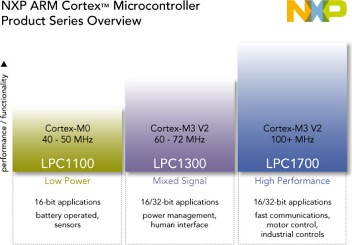
Die LPC-Familie von NXP basiert auf 32-Bit Cortex-Kernen von ARM und arbeitet mit bis zu 204MHz. Die verschiedenen Serien basieren auf den Cortex-M0/M0+/M3/M4-Kernen und sind inzwischen auch für Privatnutzer zu Preisen erhältlich, die mit denen von 8-Bit-Mikrocontrollern vergleichbar sind. Eine Auflistung der verschiedenen Typen findet sich in der Tabelle unten. Die mittlerweile veraltete LPC2000-Reihe mit ARM7TDMI-Kern wird auf einer separaten Seite beschrieben.
Von NXP sind preiswerte Entwicklungskits (ca. 25€ für Evaluation-Board incl. USB-JTAG Programmer und Debugger oder den neuen LPC-Link2, ein reiner Programmer + Debugger) erhältlich z.B. bei Watterott. Siehe dazu auch die Dokumentation von NXP zu den LPCXpresso-Entwicklungskits (PDF) und diese LPC1xxx Entwicklungskit LPCXpresso.
Vergleich aller Typen
Stand Feb. 2017
| CPU | Max. Frequency | Flash | SRAM | Voltage | Features | |
|---|---|---|---|---|---|---|
| LPC800 | Cortex-M0+ | 30MHz | 8-32kB | 1-8kB | 1.8-3.6V |
SCTimer/PWM, Switch Matrix, Pattern Match Engine |
| LPC54000 | Cortex-M41 | 180MHz | 128-512kB | 96-200kB | 1.62-3.6V |
USB, CAN, LCD, Ethernet, FlexComm, Security |
| LPC1100 | Cortex-M0/M0+ | 50MHz | 4-256kB | 1-36kB | 1.71-3.6V |
USB, CAN, EEPROM |
| LPC1200 | Cortex-M0 | 32-128kB | 4-8kB | 1.8-3.6V |
8 kV protection, IEC 60730 Class B certified | |
| LPC1300 | Cortex-M3 | 72MHz | 8-64kB | 4-12kB | 2.0-3.6V |
USB |
| LPC1500 | 64-256kB | 12-36kB | 2.4-3.6V |
USB, CAN, QEI | ||
| LPC1700 | 120MHz | 32-512kB | 8-96kB |
USB, CAN, Ethernet, LCD, QEI | ||
| LPC1800 | 180MHz | Flashless,
512kB-1MB |
104-200kB |
Dual HS USB, CAN, Ethernet, LCD, Security | ||
| LPC4000 | Cortex-M4 | 120MHz | 64-512kB | 24-96kB |
USB, CAN, Ethernet, LCD | |
| LPC4300 | Cortex-M41 | 204MHz | Flashless,
512kB-1MB |
104-282kB |
Dual HS USB, CAN, Ethernet, LCD, SGPIO, Security |
1: gibt es auch als Mehrkern-Prozessoren (mit 0/1/2 Cortex-M0(+)-Cores)
Allgemeine Informationen
Aktuelle Linecard von NXP: http://www.nxp.com/assets/documents/data/en/product-selector-guide/LPCMICROLNCD.pdf
Allgemeine Infos + User-Manuals
Eckdaten LPC8xx (Cortex-M0+)
Die sehr stromsparende LPC8xx ist nur in Packages mit einer relativ niedrigen Pinanzahl (DIP8, SO20, TSSOP16, TSSOP20) verfügbar, hat zwischen 4-16kB Flash, und 1-4kB RAM. Die zulässige Betriebsspannung liegt zwischen 1,8V und 3,6V.
Überblick über die Features der LPC800-Serie:
- 1-4 I2C
- 1-2 SSP
- 2-3 UART
- 4 Timer, 1 OS-Timer
- 1 watch dog
- 4 PWM-Einheiten
- 12-bit ADC
- CRC engine
- DMA with 18 channels and 9 trigger inputs
- 1 SCT (state configurable timer)
User Manual der LPC8-Familie (PDF)
Eckdaten LPC11xx (Cortex-M0)
Die sehr stromsparende LPC11xx-Serie (3,3V) bietet viele Möglichkeiten
- Der LPC1100L ist derzeit laut NXP (Sep2011) der preisgünstigste ARM auf dem Markt. Der 32Bit ARM mit einer Performance von ca. 45DMIPS @50MHZ benötigt bei dieser Taktfrequenz nur etwa 10mA. (Details siehe NXP-Seite)
- Überblick über die Features :
- LPC1100 Serie: • I2C, SSP, UART, GPIO, • Timers and watch dog timer, • 10-bit ADC, • Flash/SRAM memory, • Weitere Funktionen, siehe 2.3 Features
- LPC1100L Serie zusätzlich zu LPC1100: • Power Profile mit lower power consumption in Active- und Sleep-mode, • Interne pull-ups auf VDD level, • Programmierbarer pseudo open-drain mode für GPIO Pins, • WWDT mit Clock Source Lock.
- LPC11C00 Serie zusätzlich zu LPC1100: • CAN controller, • On-chip CAN Treiber, • On-chip CAN Transceiver (LPC11C2x), • WDT (not windowed) mit Clock Source Lock.
User Manual der LPC11-Familie (PDF)
- Besonderes Augenmerk möchte ich auf die neue Serie LPC111xFD legen, denn in jetzt gibt es den Cortex-M0 auch im DIL 28 den LPC1114FN28
- Des Weiteren sind damit SO20, sowie TSSOP20 und TSSOP28 Bauformen verfügbar
Eckdaten LPC12xx (Cortex-M0)
- Die Low Power LPC12xx-Serie (3,3V) ist laut NXP (Sep2011) ein Cortex-M0 mit 32 bis 128kB Flash, einem 45 CoreMark™ Benchmark-Score bei 30MHz, 2 bis 8kB SRAM, und einem internen 1% genauen 12MHz Oscillator.
- Überblick über die Features: fMAX von 30MHz, 1 10-Bit ADC mit 8 Kanälen, 2 Comparatoren, 2 UARTs, 1 SSP/SPI, 1 I2C, DMA Controller, CRC Engine, 1 32-Bit, 5 Timer (16- und 32-Bit, + RTC), 13 PWM Kanäle, bis zu 55 GPIOs.
User Manual der LPC12xx-Familie (PDF)
Eckdaten LPC13xx (Cortex-M3)
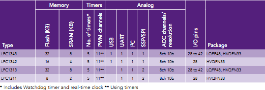
Die sehr stromsparende LPC13xx-Serie (3,3V) bietet im LQFP 48 Gehäuse 8..32k Flash, 2..8k SRAM, 5 Timer (mit WD), 11 PWM, 1 UART, 1IIC, 1USB, 1..2 SPI, einen 8-Kanal/10Bit AD-Wandler und eine Taktfrequenz von max. 72MHz.
User Manual der LPC13xx-Familie (PDF)
Eckdaten LPC17xx (Cortex-M3)
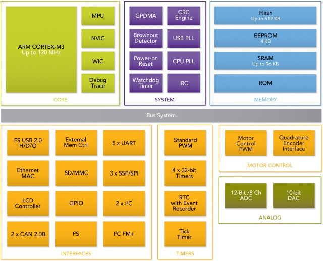
Die LPC17xx-Serie hingegen enthält eine weit größere Peripherie in einem LQFP80/100/144/208 Package. 32..512k Flash, 8..96k SRAM, 6 Timer (mit WD), 6 zusätzliche PWM-Einheiten, teilweise Ethernet und STN/TFT-LCD-Controller, meist USB (teilw. mit Host+OTG), 4 UART, 2..3IIC, 1..2 CAN, 1 SPI, 2 SSP/SPI einen 6..8-Kanal/12Bit AD-Wandler, einen 10Bit DAC, Motor-Control-Einheiten, einen Encoder-Eingang und eine Taktfrequenz von max. 100MHz(120MHz) und vieles mehr.
User Manual der LPC17xx-Familie (PDF)
Eckdaten LPC18xx (Cortex-M3)
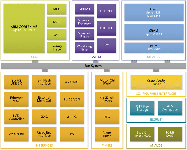
Die LPC18xx-Serie stellt DIE "High-Performance" Controller aus der Cortex-M3-Serie. Die Taktfrequenz geht bis 150MHz, die Controller enthalten große dual-Bank Flash Speicher bis zu 1MB, ein großes On-Chip SRAM mit bis zu 200KB, zusätzliche Peripherie wie z.B. SPI Flash Interface (SPIFI) und State Configurable Timer (SCT), 2x High Speed USB (1x mit On-Chip HS PHY) und eine MPU.
User Manual der LPC18xx-Familie (PDF)
Überblick über die Features: LPC18xx Flyer von NXP
Entwicklungskits
Von NXP sind sehr preiswerte Entwicklungskits (ca. 25€ für. USB-JTAG Programmer und Debugger) erhältlich z.B. Watterott. Siehe dazu auch die Dokumentation von NXP zu den LPCXpresso-Entwicklungskits (PDF).
Kostenlose Entwicklungsumgebung für ALLE hier genannten Controller
Für die ganze Prozessorfamilie ist eine kostenlose Entwicklungsumgebung erhältlich. Informationen unter lpcware: Die auf Eclipse basierende Entwicklungsumgebung ist nach der Installation bis 8k freigeschaltet und nach einer einfachen und kostenlosen Registrierung für 256kB. Die IDE ist auch für Linux und Mac verfügbar.
Hier die Installationsanleitung
LPC8xx
Familienübersicht LPC8xx
Bezugsquellen und Preise (Stand 06/2016)
- LPC810FN8 (DIP8): Digikey 1,09 € (bei einem Stuck).
- LPC812JD20 (SOIC-W 20): Digikey 1,26 € (bei einem Stuck).
- LPC812JDH20 (TSSOP-20): Digikey 1,44 € (bei einem Stuck).
- LPC824M201JDH20J (TSSOP-20): Conrad 2,99 € incl. MwSt, (2017/03)
- LPC812M101JD20FP (SO-20): Conrad 2,49 incl. MwSt, (2017/03)
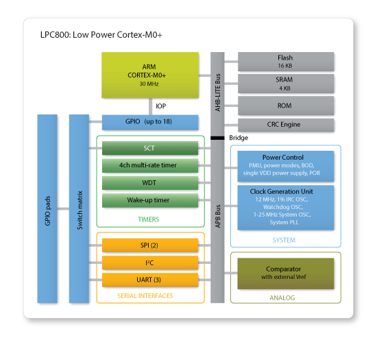
Blockdiagramm der LPC8xx Familie
Features eines LPC8xx
- System:
- ARM Cortex-M0+ processor, running at frequencies of up to 30 MHz.
- single cycle multiplier
- single cycle I/O port
- ARM Cortex-M0+ built-in Nested Vectored Interrupt Controller (NVIC).
- Serial Wire Debug, Micro Trace Buffer supported.
- System tick timer.
- Memory:
- 32kB (LPC824), 16 kB (LPC812M101JD20/LPC812M101JDH20/LPC812M101JDH16), 8 kB (LPC811M001JDH16) or 4kB (LPC810M021FN8) on-chip flash programming memory.
- 8kB, 4kB, 2 kB, or 1 kB SRAM.
- In-System Programming (ISP) and In-Application Programming (IAP) via on-chip bootloader software.
- ROM support routines for: power profiles, USART, SPI, I2C, ADC, integer division
- Digital peripherals:
- Up to 18 General Purpose I/O (GPIO) pins with configurable pull-up/pull-down resistors. Number of GPIO pins is reduced for smaller packages down to 6.
- GPIO pins can be used as edge and level sensitive interrupt sources.
- High-current output driver (20 mA) on one pin.
- High-current sink drivers (20 mA) on two open drain pins.
- Four general purpose timers/counters with a total of four capture inputs and up to 13 match outputs.
- Programmable WatchDog Timer (WDT).
- Switch matrix for flexible configuration of each I/O pin function.
- CRC engine
- DMA with 18 channels and 9 sources
- Analog peripherals:
- Comparator with internal and external references and 31 step voltage divider.
- Serial interfaces:
- UART with fractional baud rate generation, internal FIFO, and RS-485 support.
- SPI controllers with SSP features and with FIFO and multi-protocol capabilities.
- I2C-bus interface supporting full I2C-bus specification and Fast-mode Plus with a data rate of 1 Mbit/s with multiple address recognition and monitor mode.
- Clock generation:
- 12 MHz internal RC oscillator trimmed to 1% accuracy that can optionally be used as a system clock.
- Crystal oscillator with an operating range of 1 MHz to 25 MHz.
- Programmable watchdog oscillator with a frequency range of 9.4 kHz to 2.3 MHz.
- 10 kHz low-power oscillator for the WKT.
- PLL allows CPU operation up to the maximum CPU rate without the need for a high-frequency crystal. May be run from the system oscillator or the internal RC oscillator.
- Clock output function with divider that can reflect the system oscillator clock, IRC clock, CPU clock, and the Watchdog clock.
- Power control:
- Integrated PMU (Power Management Unit) to minimize power consumption during Sleep, Deep-sleep, and Deep power-down modes.
- Power profiles residing in boot ROM allowing to optimize performance and minimize power consumption for any given application through one simple function call.
- Reduced power modes: Sleep mode, Deep-sleep mode, Power-down mode, and Deep power-down mode.
- Wake-up from Deep-sleep and Power-down modes on activity on USART, SPI, and I2C peripherals.
- Brownout detect.
- Unique device serial number for identification.
- Single 3.3 V power supply (1.8 V to 3.6 V).
- Available as DIP8, TSSOP16, SO20, and TSSOP20 package.
LPC11xx
Familienübersicht LPC11xx
Bezugsquellen und Preise (Stand 01/2014):
elpro.org: von 1.61EUR (LPC1111FN33) bis 5.73EUR (LPC11U37) bei einen Stueck. Die Familie ist sehr gross mit sehr unterschiedlichen Ausfuehrungen.
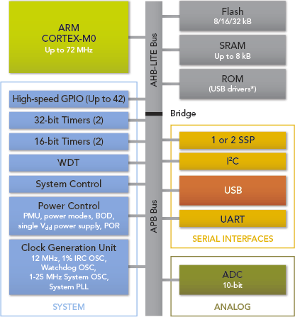
Blockdiagramm der LPC11xx Familie
Features eines LPC11xx
- System:
- ARM Cortex-M0 processor, running at frequencies of up to 50 MHz.
- ARM Cortex-M0 built-in Nested Vectored Interrupt Controller (NVIC).
- Serial Wire Debug.
- System tick timer.
- Memory:
- 32 kB (LPC1114/LPC11C14), 24 kB (LPC1113), 16 kB (LPC1112/LPC11C12), or 8 kB (LPC1111) on-chip flash programming memory.
- 8 kB, 4 kB, or 2 kB SRAM.
- In-System Programming (ISP) and In-Application Programming (IAP) via on-chip bootloader software.
- Digital peripherals:
- Up to 42 General Purpose I/O (GPIO) pins with configurable pull-up/pull-down resistors. Number of GPIO pins is reduced for smaller packages and LPC11C22/C24.
- GPIO pins can be used as edge and level sensitive interrupt sources.
- High-current output driver (20 mA) on one pin.
- High-current sink drivers (20 mA) on two open drain pins.
- Four general purpose timers/counters with a total of four capture inputs and up to 13 match outputs.
- Programmable WatchDog Timer (WDT).
- Analog peripherals:
- 10-bit ADC with input multiplexing among 8 pins.
- Serial interfaces:
- UART with fractional baud rate generation, internal FIFO, and RS-485 support.
- SPI controllers with SSP features and with FIFO and multi-protocol capabilities.
- I2C-bus interface supporting full I2C-bus specification and Fast-mode Plus with a data rate of 1 Mbit/s with multiple address recognition and monitor mode.
- Clock generation:
- 12 MHz internal RC oscillator trimmed to 1% accuracy that can optionally be used as a system clock.
- Crystal oscillator with an operating range of 1 MHz to 25 MHz.
- Programmable watchdog oscillator with a frequency range of 7.8 kHz to 1.8 MHz.
- PLL allows CPU operation up to the maximum CPU rate without the need for a high-frequency crystal. May be run from the system oscillator or the internal RC oscillator.
- Clock output function with divider that can reflect the system oscillator clock, IRC clock, CPU clock, and the Watchdog clock.
- Power control:
- Integrated PMU (Power Management Unit) to minimize power consumption during Sleep, Deep-sleep, and Deep power-down modes.
- Power profiles residing in boot ROM allowing to optimize performance and minimize power consumption for any given application through one simple function call.
- Processor wake-up from Deep-sleep mode via a dedicated start logic using up to 13 of the functional pins.
- Power-On Reset (POR).
- Brownout detect with four separate thresholds for interrupt and forced reset.
- Unique device serial number for identification.
- Single 3.3 V power supply (1.8 V to 3.6 V).
- Available in the following packages: 16WLCSP, 25WLCSP 20-SOIC, 20-TSSOP, 28-DIP, 28-TSSOP, 48-LQFP, 64-LQFP, 100-LQFP, and others.
LPC12xx
Familienübersicht LPC12xx
Bezugsquellen und Preise:
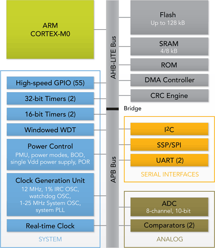
Blockdiagramm der LPC12xx Familie
Features eines LPC12xx
- Processor core
- ARM Cortex-M0 processor, running at frequencies of up to 45 MHz (one wait state from flash) or 30 MHz (zero wait states from flash). The LPC122x have a high score of over 45 in CoreMark CPU performance benchmark testing, equivalent to 1.51/MHz.
- ARM Cortex-M0 built-in Nested Vectored Interrupt Controller (NVIC).
- Serial Wire Debug (SWD).
- System tick timer.
- Memory
- Up to 8 kB SRAM.
- Up to 128 kB on-chip flash programming memory.
- In-System Programming (ISP) and In-Application Programming (IAP) via on-chip bootloader software.
- Includes ROM-based 32-bit integer division routines.
- Clock generation unit
- Crystal oscillator with an operating range of 1 MHz to 25 MHz.
- 12 MHz Internal RC (IRC) oscillator trimmed to 1 % accuracy that can optionally be used as a system clock.
- PLL allows CPU operation up to the maximum CPU rate without the need for a high-frequency crystal. May be run from the system oscillator or the internal RC oscillator.
- Clock output function with divider that can reflect the system oscillator clock, IRC clock, main clock, and Watchdog clock.
- Real-Time Clock (RTC).
- Digital peripherals
- Micro DMA controller with 21 channels.
- CRC engine.
- Two UARTs with fractional baud rate generation and internal FIFO. One UART with RS-485 and modem support and one standard UART with IrDA.
- SSP/SPI controller with FIFO and multi-protocol capabilities.
- I2C-bus interface supporting full I2C-bus specification and Fast-mode Plus with a data rate of 1 Mbit/s with multiple address recognition and monitor mode. I2C-bus pins have programmable glitch filter.
- Up to 55 General Purpose I/O (GPIO) pins with programmable pull-up resistor, open-drain mode, programmable digital input glitch filter, and programmable input inverter.
- Programmable output drive on all GPIO pins. Four pins support high-current output drivers.
- All GPIO pins can be used as edge and level sensitive interrupt sources.
- Four general purpose counter/timers with four capture inputs and four match outputs (32-bit timers) or two capture inputs and two match outputs (16-bit timers).
- Windowed WatchDog Timer (WWDT).
- Analog peripherals
- One 8-channel, 10-bit ADC.
- Two highly flexible analog comparators. Comparator outputs can be programmed to trigger a timer match signal or can be used to emulate 555 timer behavior.
- Power
- Three reduced power modes: Sleep, Deep-sleep, and Deep power-down.
- Processor wake-up from Deep-sleep mode via start logic using 12 port pins.
- Processor wake-up from Deep-power down and Deep-sleep modes via the RTC.
- Brownout detect with three separate thresholds each for interrupt and forced reset.
- Power-On Reset (POR).
- Integrated PMU (Power Management Unit).
- Unique device serial number for identification.
- 3.3 V power supply.
- Available as 64-pin and 48-pin LQFP package.
LPC13xx
Familienübersicht LPC13xx
Bezugsquellen und Preise:
LPC1313 mit 32k-Flash mit 72MHz im LQFP 48 Gehäuse. Der LPC1313 ist bei Darius erhältlich für 3,57 € (Juli 2016), oder elpro.org für 2,29 €. Entwicklungskit INKLUSIVE JTAG-Programmer & Debugger bei Watterott für 23,80 € (Juli 2011)
Blockdiagram der LPC13xx Familie
Features eines LPC1313
- ARM Cortex-M3 processor, running at frequencies of up to 72 MHz.
- ARM Cortex-M3 built-in Nested Vectored Interrupt Controller (NVIC).
- 32 kB on-chip flash programming memory.
- 8 kB SRAM.
- In-System Programming (ISP) and In-Application Programming (IAP) via on-chip bootloader software.
- UART with fractional baud rate generation, modem, internal FIFO, and RS-485/EIA-485 support.
- SSP controller with FIFO and multi-protocol capabilities.
- Additional SSP controller on LPC1313FBD48/01.
- I2C-bus interface supporting full I2C-bus specification and Fast-mode Plus with a data rate of 1 Mbit/s with multiple address recognition and monitor mode.
- Up to 42 General Purpose I/O (GPIO) pins with configurable pull-up/pull-down resistors.
- Four general purpose counter/timers with a total of four capture inputs and 13 match outputs.
- Programmable Watchdog Timer (WDT)
- System tick timer.
- Serial Wire Debug and Serial Wire Trace port.
- High-current output driver (20 mA) on one pin.
- High-current sink drivers (20 mA) on two I2C-bus pins in Fast-mode Plus.
- Integrated PMU (Power Management Unit) to minimize power consumption during Sleep, Deep-sleep, and Deep power-down modes.
- Three reduced power modes: Sleep, Deep-sleep, and Deep power-down.
- Single power supply (2.0 V to 3.6 V).
- 10-bit ADC with input multiplexing among 8 pins.
- GPIO pins can be used as edge and level sensitive interrupt sources.
- Clock output function with divider that can reflect the system oscillator clock, IRC clock, CPU clock, or the watchdog clock.
- Processor wake-up from Deep-sleep mode via a dedicated start logic using up to 40 of the functional pins.
- Brownout detect with four separate thresholds for interrupt and one thresholds for forced reset.
- Power-On Reset (POR).
- Integrated oscillator with an operating range of 1 MHz to 25 MHz.
- 12 MHz internal RC oscillator trimmed to 1 % accuracy over the entire temperature and voltage range that can optionally be used as a system clock.
- Programmable watchdog oscillator with a frequency range of 7.8 kHz to 1.8 MHz. System PLL allows CPU operation up to the maximum CPU rate without the need for a high-frequency crystal. May be run from the system oscillator or the internal RC oscillator.
- Code Read Protection (CRP) with different security levels.
- Unique device serial number for identification.
- Available as 48-pin LQFP package and 33-pin HVQFN package.
Features eines LPC1347
- 64 kB Flash
- 12 kB SRAM
- 4 kB EEPROM
- 12 Bit ADC
- USB Code in ROM
- USB Bootloader in ROM, programming via copy to mass storage device
LPC17xx
Familienübersicht LPC17xx
Bezugsquellen und Preise:
LPC1754 mit 128K Flash im LQFP80, der bei Darius für 7€74 (Juli/2011) erhältlich ist,[den LPC1751 (32k/8k) schon für 5€95] und bei Digikey für 6€35, den LPC1764FBD100 bei TME für 7€ Entwicklungskit INCLUSIVE JTAG-Programmer & Debugger bei Watterott für 23€80 (Juli/2011)
Blockdiagram der LPC17xx Familie
Features eines LPC1754
- ARM Cortex-M3 processor, running at frequencies of up to 100 MHz
- A Memory Protection Unit (MPU) supporting eight regions is included.
- ARM Cortex-M3 built-in Nested Vectored Interrupt Controller (NVIC).
- 128 kB on-chip flash program memory with In-System Programming (ISP) and In-Application Programming (IAP) capabilities.
- 32 kB of SRAM on the CPU with local code/data bus for high-performance CPU access.
- Eight channel General Purpose DMA controller
- Serial interfaces:
- USB 2.0 full-speed controller that can be configured for either device, Host, or OTG operation with an on-chip PHY for device and Host functions
- Four UARTs with fractional baud rate generation, internal FIFO, IrDA, and DMA, Einer mit Modem I/Os und RS485 Support
- 1 CAN controller.
- 2 SSP controllers
- 1 SPI controller
- 2 I2C-bus interfaces with data rates of 1Mbit/s,
- I2S (Inter-IC Sound)
- 52 General Purpose I/O (GPIO) pins Any pin of ports 0 and 2 can be used to generate an interrupt.
- 8x 12-bit Analog-to-Digital Converter (ADC) conversion rates up to 200 kHz
- 1x 10-bit Digital-to-Analog Converter (DAC)
- Four general purpose timers/counters, with a total of eight capture inputs and ten compare outputs.
- One motor control PWM with support for three-phase motor control.
- Quadrature encoder interface that can monitor one external quadrature encoder.
- One standard PWM/timer block with external count input.
- Real-Time Clock (RTC) with a separate power domain including 20 bytes of battery-powered backup registers, An RTC interrupt can wake up the CPU from any reduced power mode.
- Watchdog Timer (WDT).
- Cortex-M3 system tick timer
- Repetitive interrupt timer
- Standard JTAG test/debug interface as well as Serial Wire Debug and Serial Wire Trace Port options.
- Four reduced power modes: Sleep, Deep-sleep, Power-down, and Deep power-down.
- Single 3.3 V power supply (2.4 V to 3.6 V).
- Four external interrupt inputs configurable as edge/level sensitive. All pins on PORT0 and PORT2 can be used as edge sensitive interrupt sources.
- Non-maskable Interrupt (NMI) input.
- Wakeup Interrupt Controller (WIC)
- Each peripheral has its own clock divider for further power savings.
- Brownout detect with separate threshold for interrupt and forced reset.
- On-chip Power-On Reset (POR).
- On-chip crystal oscillator with an operating range of 1 MHz to 25 MHz.
- 4 MHz internal RC oscillator trimmed to 1% accuracy that can optionally be used as a system clock.
- An on-chip PLL allows CPU operation up to the maximum CPU rate without the need for a high-frequency crystal. May be run from the main oscillator, the internal RC oscillator, or the RTC oscillator.
- Available as 80-pin LQFP (12 x 12 x 1.4 mm) packages.
LPC18xx
Familienübersicht LPC18xx
Bezugsquellen und Preise:
Blockdiagramm der LPC18xx Familie
Features eines LPC18xx
DRAFT!
- Processor core
- ARM Cortex-M3 processor, running at frequencies of up to 180 MHz.
- ARM Cortex-M3 built-in Memory Protection Unit (MPU) supporting eight regions.
- ARM Cortex-M3 built-in Nested Vectored Interrupt Controller (NVIC).
- Non-maskable Interrupt (NMI) input.
- JTAG and Serial Wire Debug, serial trace, eight breakpoints, and four watch points.
- ETM and ETB support.
- System tick timer.
- On-chip memory (flashless parts LPC1850/30/20/10)
- Up to 200 kB SRAM total for code and data use.
- Two 32 kB SRAM blocks with separate bus access. Both SRAM blocks can be powered down individually.
- 64 kB ROM containing boot code and on-chip software drivers.
- 32-bit One-Time Programmable (OTP) memory for general-purpose customer use.
- On-chip memory (parts with on-chip flash)
- Up to 1 MB total dual bank flash memory with flash accelerator.
- In-System Programming (ISP) and In-Application Programming (IAP) via on-chip bootloader software.
- Up to 136 kB SRAM for code and data use.
- Two 32 kB SRAM blocks with separate bus access. Both SRAM blocks can be powered down individually.
- 32 kB ROM containing boot code and on-chip software drivers.
- 32-bit One-Time Programmable (OTP) memory for general-purpose customer use.
- Clock generation unit
- Crystal oscillator with an operating range of 1 MHz to 25 MHz.
- 12 MHz internal RC oscillator trimmed to 1 % accuracy.
- Ultra-low power RTC crystal oscillator.
- Three PLLs allow CPU operation up to the maximum CPU rate without the need for a high-frequency crystal. The second PLL is dedicated to the High-speed USB, the third PLL can be used as audio PLL.
- Clock output.
- Serial interfaces:
- Quad SPI Flash Interface (SPIFI) with four lanes and data rates of up to 40 MB per second total.
- 10/100T Ethernet MAC with RMII and MII interfaces and DMA support for high throughput at low CPU load. Support for IEEE 1588 time stamping/advanced time stamping (IEEE 1588-2008 v2).
- One High-speed USB 2.0 Host/Device/OTG interface with DMA support and on-chip PHY.
- One High-speed USB 2.0 Host/Device interface with DMA support, on-chip full-speed PHY and ULPI interface to external high-speed PHY.
- USB interface electrical test software included in ROM USB stack.
- Four 550 UARTs with DMA support: one UART with full modem interface; one UART with IrDA interface; three USARTs support synchronous mode and a smart card interface conforming to ISO7816 specification.
- Two C_CAN 2.0B controllers with one channel each.
- Two SSP controllers with FIFO and multi-protocol support. Both SSPs with DMA support.
- One Fast-mode Plus I2C-bus interface with monitor mode and with open-drain I/O pins conforming to the full I2C-bus specification. Supports data rates of up to 1 Mbit/s.
- One standard I2C-bus interface with monitor mode and standard I/O pins.
- Two I2S interfaces with DMA support, each with one input and one output.
- Digital peripherals:
- External Memory Controller (EMC) supporting external SRAM, ROM, NOR flash, and SDRAM devices.
- LCD controller with DMA support and a programmable display resolution of up to 1024H x 768V. Supports monochrome and color STN panels and TFT color panels; supports 1/2/4/8 bpp CLUT and 16/24-bit direct pixel mapping.
- SD/MMC card interface.
- Eight-channel General-Purpose DMA (GPDMA) controller can access all memories on the AHB and all DMA-capable AHB slaves.
- Up to 80 General-Purpose Input/Output (GPIO) pins with configurable pull-up/pull-down resistors and open-drain modes.
- GPIO registers are located on the AHB for fast access. GPIO ports have DMA support.
- State Configurable Timer (SCT) subsystem on AHB.
- Four general-purpose timer/counters with capture and match capabilities.
- One motor control PWM for three-phase motor control.
- One Quadrature Encoder Interface (QEI).
- Repetitive Interrupt timer (RI timer).
- Windowed watchdog timer.
- Ultra-low power Real-Time Clock (RTC) on separate power domain with 256 bytes of battery powered backup registers.
- Alarm timer; can be battery powered.
- Digital peripherals available on flash-based parts LPC18xx only:
- <tbd>
- Analog peripherals:
- One 10-bit DAC with DMA support and a data conversion rate of 400 kSamples/s.
- Two 10-bit ADCs with DMA support and a data conversion rate of 400 kSamples/s.
- Security:
- Hardware-based AES security engine programmable through an on-chip API.
- Two 128-bit secure OTP memories for AES key storage and customer use.
- Unique ID for each device.
- Power:
- Single 3.3 V (2.2 V to 3.6 V) power supply with on-chip internal voltage regulator for the core supply and the RTC power domain.
- RTC power domain can be powered separately by a 3 V battery supply.
- Four reduced power modes: Sleep, Deep-sleep, Power-down, and Deep power-down.
- Processor wake-up from Sleep mode via wake-up interrupts from various eripherals.
- Wake-up from Deep-sleep, Power-down, and Deep power-down modes via external interrupts and interrupts generated by battery powered blocks in the RTC power domain.
- Brownout detect with four separate thresholds for interrupt and forced reset.
- Power-On Reset (POR).
- Available as 100-pin, 144-pin, and 208-pin LQFP packages and as 100-pin, 180-pin, and 256-pin LBGA packages.
Entwicklungsumgebungen
MCUXpresso
Neu, seit 2017/04 verfügbar
- kostenlos, ohne Codelimits
- Unterstützung für LPC und Kinetis Familie
- läuft unter Windows, Linux, MacOS
- sieht genauso aus wie LPCXpresso
- Projekte die mit LPCXpresso erstellt wurden lassen sich mit MCUXpresso öffnen
weitere Infos unter: http://www.nxp.com/products/software-and-tools/run-time-software/mcuxpresso-software-and-tools/mcuxpresso-integrated-development-environment-ide:MCUXpresso-IDE
LPCWare (kostenlos)
Entwicklungs Tool
(Beschreibung aus der Web-Site:) LPCXpresso's IDE (Ursprünglich von "Code RED" entwickelt, die Firma wurde 2013 von LPC gekauft) ist eine hoch integrierte Entwicklungsumgebung für LPC-Controller, und beinhaltet alle zur Entwicklung erforderlichen Tools um hoch qualitative Software in einer angemessenen Zeit zu schreiben. LPCXpresso basiert auf ein vereinfachtes Eclipse mit vielen LPC-specifischen Erweiterungen. Des Weiteren ist eine aktuelle Version der Industrie-Standard GNU Tool-Chain mit einer propritären und optimierten C-Lib mit dabei. Die LPCXpresso IDE stellt ein voll optimiertes Executable zur Verfügung. Die einzige Beschränkung der kostenlosen Version ist eine Limitierung auf 256kB Code nach erfolgter Registrierung. Das LPCXpresso Target Board ist eine Gemeinschaftsentwicklung von Embedded Artists, Code Red und NXP.
Features
Die LPCXpresso IDE stellt eine C-Umgebung mit Syntax-Colouring, Source-Formatierung, Funktions-Folding, sowie mit Online- und Offline Hilfe und umfangreichen Projekt-Management Funktionen zur Verfügung. Dies beinhaltet:
- Wizards um Projekte für alle unterstützten Controller zu erstellen
- Automatische Linker Script Generierung inklusive Memory-Map Unterstützung
- Programmierung des Controllers
- On-Line Debugging
- Datenblatt-Zugriff über eingebauten Browser
- Support für die NXP LPC Microcontroller Familien, von Cortex-M0, Cortex-M3 bis Cortex-M4 und ARM7 bis ARM9
Peripherie und Register Views im Debugger
Der Peripherie-Viewer im integrierten Debugger zeigt alle Register und Bit-Felder in einer einfachen Baumstruktur. Ein Prozessor-Register Viewer erlaubt den Zugriff auf alle Prozessor-Register und stellt eine "Smart-Formatting" Funktion zur Verfügung um komplexe Register wie Flags oder Status Register übersichtlich darstellen zu können.
Unterstützte Familien
Cortex-M0, Cortex-M3, Cortex-M4, Einzelne Controller aus der LPC2000 family, ARM966, ARM926-EJ, ARM926-EJ + VFP
Sehr preiswerter USB_JTAG_SWD Debugger
Von NXP sind sehr preiswerte Entwicklungskits (ca. 25€ für Evaluation-Board incl. USB-JTAG Programmer und Debugger) erhältlich z.B. Watterott. Siehe dazu auch die Dokumentation von NXP zu den LPCXpresso-Entwicklungskits (PDF) und diese Beschreibung Der neue Programmer/Debugger ist hier für ca 18€ +P&P erhältlich Programmer
Standard Library
Im Download der "Code Red" Entwicklungsumgebung ist eine relativ umfangreiche Firmwarebibliothek vorhanden.
Installationsanleitung zur IDE
Codebase für LPC11xx und LPC13xx
Für die Cortex-M0 und -M3 Familien existieren verschiedene Basispakete die als Startausstattung sehr gut geeignet sind. Auf microbuilder.eu findet man eine sehr interessante Version inklusive Dokumentation.
HIER findet man alle Links zur original Codebase mit allen Dateien (Stand Januar 2012) aber auch eine deutsche Übersetzung zu den Files.
CooCox
Auf der Homepage von CooCox - einem chinesischen Open-Source Projekt, auf der eine IDE für Atmel, Energy Micro, Holtek, Nuvoton, ST, TI und NXP verfügbar ist - findet man die auf Eclipse basierende "CooCox CoIDE", die sich aus dem "CoBuilder" und dem "CoDebugger" zusammensetzt. Des Weiteren bietet man dort ein Echtzeit-Multitasking Betriebssystem, sowie SW-Versionen von zwei unterschiedliche Debugging-Adapter und ein Stand-alone Flash-Tool zum freien Download an.
Die folgenden Controller können damit programmiert und debugged werden:
   LPC1111x101    LPC1111x201   LPC1112x101   LPC1112x201
   LPC1113x201    LPC1113x301   LPC1114x201   LPC1114x301
   LPC11C14x301   LPC11C12x301
   LPC1224x101    LPC1224x121   LPC1225x301   LPC1225x321   LPC1226x301  LPC1227x301
   LPC1311   LPC1313   LPC1342   LPC1343
   LPC1751   LPC1752   LPC1754   LPC1756   LPC1758   LPC1759
   LPC1763   LPC1764   LPC1765   LPC1766   LPC1767   LPC1768   LPC1769
EmBlocks
Emblocks ist eine kostenlose Entwicklungsumgebung. Sie unterstützt neben NXP uC weitere ARM uC (STM32, EFM32) sowie PIC, AVR und MSP430. Die IDE hat einen eingebauten GDB Debugger welcher System view (Peripherie Register anzeigen) beim Debuggen unterstützt. Ausserdem gibt es einen Project Wizzard für NXP uC
Unterstützt wird der JLINK mit folgenden NXP uC:
LPC11Axx, LPC11Exx, LPC11Uxx, LPC11xxLV, LPC12xx, LPC13Uxx, LPC13xx, LPC17xx, LPC18xx, LPC18xx, LPC177x_8x, LPC407x_8x
Codebase
Des Weiteren existiert eine umfangreiche Sammlung von Code-Beispielen.
Keil
KEIL MDK-ARM (Windows, Free Version auf 32KB begrenzt, mit vielen Beispielen zu div. Evaluation Boards)
WinARM
WinARM (wird derzeit nicht gepflegt)
GNUARM
GNUARM (Linux, Windows, wird derzeit nicht gepflegt),
Yagarto
Yagarto (Windows, mit Eclipse-Integration)
CodeSourcery
CMSIS - Standard für alle Plattformen
Der Cortex Microcontroller Software Interface Standard (CMSIS) stellt einen "abstraction layer" für alle Cortex-Mx Controller zur Verfügung.
CMSIS stellt einen Schnittstellenstandard von ARM dar, der von vielen Tool-Herstellern unterstützt wird und ist (laut verschiedener Berichte) kompatibel mit den verschiedensten Compilern (incl GCC). Dies wird erreicht durch einheitliche Definitionen für Adressen und Namen die den Zugriff auf die Register des Cores und der Peripherie ermöglichen. Auch Standard-Funktionen für den Start und die Interrupts stehen zur Verfügung. Natürlich kann auch weiterhin direkt auf die HW zugegriffen werden, es geht nur um eine Vereinheitlichung von identischen Funktionen. Da die Peripherie-Teile zumindest innerhalb eines Halbleiterherstellers für die Cortex-Mx Controller sehr ähnlich oder sogar weitgehend identisch sind kann deutlich mehr SW für verschiedene Derivate innerhalb dieser Prozessorfamilien wiederverwendet werden. (siehe Google: "CMSIS_Doulos_Tutorial.pdf").
Ein weiterer, interessanter Punkt ist die CMSIS-DSP Lib mit ihren Vektorfunktionen, Matrix-Berechnung sowie komplexen Algorithmen für Filter, Regler und Fourietransformation sowie weiterer DSP Algorithmen (insgesamt 61).
Leider hat diese Kompatibilität auch ihre Grenzen, denn Sonderfunktionen bzw. Spezialitäten in der "gleichen" Peripherie zwischen unterschiedlichen Halbleiterherstellern werden nicht abgedeckt. Wäre auch zu schön, wenn die Prozesorhersteller dem Entwickler dadurch einen fliegenden HW-Wechsel bzw. eine einfache Vergleichbarkeit ermöglichen würden ;-)
Eine komplette CMSIS-Lib (V2.0) "Cortex Microcontroller Software Interface Standard" ist für das "Code Red" Paket verfügbar, inklusive einer "DSP-Library" http://support.code-red-tech.com/CodeRedWiki/NewInVersion4 bzw. für GNU / Keil / IAR unter http://ics.nxp.com/support/documents/microcontrollers/?search=CMSIS&type=software&Search.x=8&Search.y=12
Links
- Wiki
Bezugsquellen
Controller
(Die Preiswertesten sind fett dargestellt)
Evaluation Boards
- Watterott (24€ inclusive JTAG-Programmiergerät UND JTAG Debugger für kostenlose "Code-Red" Entwicklungsplattform), dazu hier die Beschreibung
- LPC-Tools
- thinkembedded.ch div. Olimex Boards
Weblinks, Foren, Communities
- http://www.nxp.com/#/page/content=[f=/dynamic/applicationnotes/tid-50809_sid-56890/data.xml] Appnotes
- Projects
- MBED
- NXP-WIKI
- NXP-Forum
- LPCXpresso
- 32BitMicro
- SimpleCortex
- LPCWare NXP MCU community
- LPC175/6x und LPC23xx pin Configurator
- MIDI controlled monophonic synthesizer based on the LPCXpresso 1768.
- An open source software library for NXP's Cortex-M3 based LPC1300 microcontroller family
- An open source software library for NXP's Cortex-M0 based LPC1100 microcontroller family
- A flexible bootloader for use with LPC12xx Microcontrollers from NXP, Firmware code is AES128 encrypted to secure your project / source code when giving out public firmware updates.
- Read receiver and sensor signals for radio controlled model aircrafts configured for LPCXpresso
- Open toolset for LPCXpresso
- Collection of code and tools for 32 bit microcontrollers
- my-nxp-lpc1114 study course
- nxp-lpc
Entwicklungsplattformen
- LPDXpresso Download (Kostenlos mit Debugger)
- LPCXpresso Homepage
- CR-WIKI
- ARM/Keil MDK-ARM
- IAR EWARM
- Rowley Crossworks
- Green Hills Software
- CooCox (Kostenlos)
