-
Datei
lcd.asm
PORTC, temp ldi temp, (0<<PD4) | (0<<PD5) | (0<<PD6) ldi temp, (1<<PB1) out DDRB, temp rcall init_pwm rcall init_lcd rcall init_uart sei end: rjmp end wait: ldi r17, 0xFF loop: ldi r18, 0xFF inner_loop: dec r18 brne inner_loop dec r17 brne loop ret wait2: rcall wait rcall wait ret lcd_enable: sbi PORTD
in „UART Bootloader ATtiny13 - ATmega644“ · Projekte & Code ·
-
Datei
Transistortester.patch
"desconectar"; + const unsigned char F_GEN_str[] MEM2_TEXT = "F-Generador"; + const unsigned char PWM_10bit_str[] MEM2_TEXT = "10-bit PWM"; + const unsigned char RotaryEncoder_str[] MEM2_TEXT = "encoder rotativo"; + const unsigned char TURN_str[] MEM2_TEXT = "rotar!"; + const unsigned char FULLCHECK_str
-
Datei
Colortemp_tn13.txt
end: ; -------------------------------------------------------------------- count: inc PWMCount ; PWM Schleife von 0...64 cpi PWMCount,64 brne Ausgabe clr PWMCount rjmp GET_AD ; wenn fertig neuen AD-Wert holen Ausgabe: ldi temp, 0b11111000 ; LEDs an PB0:2 cp PWMCount, blau ; blau anschalten bis Grenzwert
-
Thread
[ASM & C] HD44780 an PIC24 (3.3V oder 5V)
ILC7660. Die zweite Möglichkeit ist eine diskret aufgebaute Ladungspumpe, die ihren Takt von einem PWM Pin des µC bekommt (Schaltung im Anhang). Die Ausgansspannung dieser Ladungspumpe wir über die Frequenz gesteuert. Ich habe die Schaltung mit dem eingetragenen Werten so mit einem PIC18LF25k22 getestet
Projekte & Code ·Max H. · ·1 Antworten
-
Thread
AVRMon (Wozmon) für Arduino pro mini
6E:01 ; TIMSK(TOIE0) 46 ; TCNT0 enthält den aktuellen Zählerstand Um eine PWM mit Timer0 einzustellen, gibt man ein: 45:02 ; TCCR0B(CS01) 44:83 ; TCCR0A(COM0A1|WGM01|WGM00) 2A:40 ; DDRD(PD6) 47:40 ; OCR0A Wichtig ist, alle Zeichen müssen
Projekte & Code ·Dirk R. · ·1 Antworten
-
Datei
Analog3.txt
;**************************************** ;* * ;* BARGRAPH mit 16Bit * ;* auf 8 LEDs * ;* mit SoftPWM zweistufig * ;* * ;* by Steven Wagner * ;**************************************** ;Info: ;Natürlich ist es auch möglich das Programm in eine ;Subroutine umzufunktionieren. ; .include "m16def.inc" .def
-
PDF
Using_the_Siemens_S65_Display.pdf
current. That means a relative large voltage is needed. This voltage can be easily generated with a PWM signal generator of the µC. (Do not forget to switch on the current limitation of your power supply until the PWM generator is running correct. If you drive the n-channel gate high for a longer time
in „The Siemens S65 132x176, 65536 color display with AVR“ · Projekte & Code ·
-
PDF
Using_the_Siemens_S65.pdf
current. That means a relative large voltage is needed. This voltage can be easily generated with a PWM signal generator of the µC. (Do not forget to switch on the current limitation of your power supply until the PWM generator is running correct. If you drive the n-channel gate high for a longer time
in „The Siemens S65 132x176, 65536 color display with AVR“ · Projekte & Code ·
-
Datei
lcdconpar.asm
Bereich 0-79 (plus 128, falls die * ;* Position in der unteren Displayhälfte liegt.) * ;* * ;* 002 Set PWM. Stellt das Tastverhältnis des PWM Ausgangs OC1B ein. * ;* Das Tastverhältnis folgt auf diesen Befehl als Parameter. * ;* * ;* 010 Clear Line. Dieser Befehl benötigt keinen Parameter und löscht * ;*
in „LCD Controller für 640x480 LCD mit mega8515“ · Projekte & Code ·
-
Datei
lcdconpar.asm
Bereich 0-79 (plus 128, falls die * ;* Position in der unteren Displayhälfte liegt.) * ;* * ;* 002 Set PWM. Stellt das Tastverhältnis des PWM Ausgangs OC1B ein. * ;* Das Tastverhältnis folgt auf diesen Befehl als Parameter. * ;* * ;* 003 Set X Start. Stellt den Startwert für den Zeilenbeginn ein. * ;* Damit
in „LCD Controller für 640x480 LCD mit mega8515“ · Projekte & Code ·
-
Datei
lcdconser.asm
Bereich 0-79 (plus 128, falls die * ;* Position in der unteren Displayhälfte liegt.) * ;* * ;* 002 Set PWM. Stellt das Tastverhältnis des PWM Ausgangs OC1B ein. * ;* Das Tastverhältnis folgt auf diesen Befehl als Parameter. * ;* * ;* 003 Set X Start. Stellt den Startwert für den Zeilenbeginn ein. * ;* Damit
in „LCD Controller für 640x480 LCD mit mega8515“ · Projekte & Code ·
-
Datei
lcdconser_.asm
Bereich 0-79 (plus 128, falls die * ;* Position in der unteren Displayhälfte liegt.) * ;* * ;* 002 Set PWM. Stellt das Tastverhältnis des PWM Ausgangs OC1B ein. * ;* Das Tastverhältnis folgt auf diesen Befehl als Parameter. * ;* * ;* 003 Set X Start. Stellt den Startwert für den Zeilenbeginn ein. * ;* Damit
in „LCD Controller für 640x480 LCD mit mega8515“ · Projekte & Code ·
-
Datei
lcdconser640x480.txt
Bereich 0-79 (plus 128, falls die * ;* Position in der unteren Displayhälfte liegt.) * ;* * ;* 002 Set PWM. Stellt das Tastverhältnis des PWM Ausgangs OC1B ein. * ;* Das Tastverhältnis folgt auf diesen Befehl als Parameter. * ;* * ;* 003 Set X Start. Stellt den Startwert für den Zeilenbeginn ein. * ;* Damit
in „LCD Controller für 640x480 LCD mit mega8515“ · Projekte & Code ·
-
Datei
doublepress.S
timer_prescale = (1 << CS01) ; CK/8 .equ timer_preload = 105 ;preload timer counter for 1ms (short enough for PWM) .equ debounce_interval = 10 ;# of timer calls per debounce call: 10ms .equ longpress_timeout = 100 ;# of debounce calls for long press detection: 1s .equ longpress_rpt_timeout = 50 ;# of debounce calls
in „Einzel/Doppel/Langen Tastendruck unterscheiden“ · Projekte & Code ·
-
PDF
combined_comparison.pdf
can be frozen while the PWM outputs are disabled, thereby cutting off the switches controlled by these outputs. Any general-purpose timer can be used to generate PWM output. Each timer has an independent DMA request mechanism.
-
Thread
DMX Receiver - 4Channel PWM (2*8bit lin, 2*16bit exp) - AtTiny2313
Kanäle werden jeweils mit 8Bit über DMX gesetzt, 2 davon werden über eine Exponentialtabelle auf 16Bit PWM gemapped. Die DMX Adresse wird über einen 9Pol Dip-Schalter festgelegt. Sollte der konfigurierte DMX Frame nicht korrekt empfangen werden, so deaktivieren sich alle Outputs automatisch nach 4 Sekunden
Projekte & Code ·TestX .. · ·0 Antworten
-
Thread
Halogen 4-fach Dimmer, 3 Modi AVR in C
Pflanzenlicht mit vier mal 10W Halogen - drei Modi, mehr will sie nicht (Random, Var, 2-fach gleitend) - PWM ohne Helligkeitssprünge, 64 Steps - Speed bzw. Helligkeit variabel - vier Tasten via ADC mit Entprellung & Repeat - EEPROM für letzten Mode Vielleicht kann jemand irgend was verwenden oder erweitern
Projekte & Code ·Lothar · ·0 Antworten
-
Datei
freq-gen.c
; OCR0A = 0xff; TIMSK0 = (1<<TOIE0); TCCR1A = (1<<WGM10) | (1<<WGM11) | (1<<COM1A0); // Timer1 als PWM(Frequenz) TCCR1B = (1<<CS10) | (1<<CS12) | (1<<WGM12) | (1<<WGM13); OCR1BH = 0x7f; OCR1BL = 0xff; TCCR2A = (1<<WGM20) | (1<<COM2A1); // Timer2 als PWM(Backlight LCD) TCCR2B = (1<<CS20); OCR2A = 0xff
in „Einstellbarer Frequenzgenerator für 0.12 Hz - 8 MHz mit Atmega 8 und Bascom“ · Projekte & Code ·
-
Thread
ModelServo-Signal-Serialisierer Mega8
Spaghetti-Style in 4 Blöcken + Abschluss"höcker" ab. Hab versucht aus zu baldovern, ob sich einer der PWM Modi eignet. Aber ich war mir ohne längerwieriges Einlesen in die genauen Details der Modi nicht ausreichend sicher. Das nicht ausreichend sicher in begrenzter Zeit raus zu kriegen und dem Gefühl
Projekte & Code ·Jasson J. · ·1 Antworten
-
PDF
Using_the_Siemens_S65_Display.pdf
current. That means a relative large voltage is needed. This voltage can be easily generated with a PWM signal generator of the µC. (Do not forget to switch on the current limitation of your power supply until the PWM generator is running correct. If you drive the n-channel gate high for a longer time
in „The Siemens S65 132x176, 65536 color display with AVR“ · Projekte & Code ·
-
PDF
lcdcon_320240.pdf
Display und somit den Kontrast ein. Der Kontrast lässt sich über einen kleinen Bereich per Software über PWM regeln. Sollte dieser Bereich für das LCD nicht passen, müssen R5/R4 angepasst werden. IC4B generiert aus dem RD\ Impuls und dem Enable Signal (PD3) die Shiftclock Impulse für das LCD. Damit wird das
in „Grafikfähiger LCD Controller für 320x240 LCD mit 4 Graustufen“ · Projekte & Code ·
-
PDF
textdisplayadapter.pdf
Mikrocontroller PFS154 von Padauk. Ein proprietäres Datenformat, welches letztendlich eine Pulsweitenmodulation (PWM) darstellt, nimmt die Steuerbefehle entgegen und setzt diese in die Kommandos des Displays um. Datenframe Im Ruhezustand (es wird nichts gesendet) muß die Datenleitung auf high gehalten werden. Ein
in „"Intelligenter" Textdisplayadapter mit Padauk PFS154“ · Projekte & Code ·
-
Thread
Arduino Mega 2560 & Windows per RS-232
/code] Das ist bestimmt nicht alles elegant gelöst, aber es funktioniert und man sieht bei drei PWM-Werten den Vorteil des Software-timers. Gruß Thomas
Projekte & Code ·Thomas Scherer · ·1 Antworten
-
Datei
FT800.h
REG_PLAYBACK_FORMAT 0x1024B4UL #define REG_PLAYBACK_LOOP 0x1024B8UL #define REG_PLAYBACK_PLAY 0x1024BCUL #define REG_PWM_HZ 0x1024C0UL #define REG_PWM_DUTY 0x1024C4UL #define REG_MACRO_0 0x1024C8UL #define REG_MACRO_1 0x1024CCUL #define REG_SCREENSHOT_BUSY 0x1024D8UL #define REG_CMD_READ 0x1024E4UL #define REG_CMD_WRITE
-
Datei
sd_card.c
/ 58 cutoff_value2 = ffread(); // 59 resonanc_value2 = ffread(); // 60 filtertyp = ffread(); // 61 pwm1_level = ffread(); // 62 pwm2_level = ffread(); // 63 osc1_mode = ffread(); // 64 osc2_mode = ffread(); // 65 Bitcrush_Bits = ffread(); // 66 mod_lfo1_osc1 = ffread(); // 67 mod_lfo1_osc2 = ffread()
in „MMC SD library FAT16 FAT32 read write“ · Projekte & Code ·
-
Datei
FT800.h
REG_PLAYBACK_FORMAT 0x1024B4UL #define REG_PLAYBACK_LOOP 0x1024B8UL #define REG_PLAYBACK_PLAY 0x1024BCUL #define REG_PWM_HZ 0x1024C0UL #define REG_PWM_DUTY 0x1024C4UL #define REG_MACRO_0 0x1024C8UL #define REG_MACRO_1 0x1024CCUL #define REG_SCREENSHOT_BUSY 0x1024D8UL #define REG_CMD_READ 0x1024E4UL #define REG_CMD_WRITE
-
PDF
PH320240T023-IHC06_005.pdf
0.32 0.37 Y 0.30 0.35 0.40 X 0.59 0.64 0.69 Color of CIE Red VCC=12V Y 0.29 0.34 0.39 Coordinate X PWM=”High” 0.29 0.34 0.39 - (LCD & B/L & T/P) Green (Duty=100%) Y 0.56 0.61 0.66 Note1 X 0.09 0.14 0.19 Blue Y 0.03 0.08 0.13 Average Brightness VCC=12V 2 Pattern=white display IV 680 850 - cd/m (LCD & B/L & T/P)*1 PWM=”High” Uniformity (Duty=100%) △ B 70 - - % (LCD & B/L & T/P)*2 PH320240T023-IHC06 Page6 SAMPLE Ver.01 SPEC Edi.005 Note 1: *1:△B=B(min) / B(max) * 100% *2:Measurement Condition for Optical Characteristics
-
Datei
firefly.c
/ 12 fireflies uint8_t ocr_data[6]; // OCR0A and DDRB datas for Timer0 Compare Match ISR, computed PWM Dutycycles uint16_t hungry_threshold; // threshold for lightning fireflies // 12 fixed registers assigned to speedup ISRs, Timer0 Overflow and Output Compare register uint16_t _saveZ asm("r2"); // save
in „Glühwürmchen in Rotkohlglas gefangen“ · Projekte & Code ·
-
PDF
MW-RSP150-Pollin-352477.pdf
2 2 or equivalent or equivalent 1 RC- 6.56.5 4-M4(Both Sides) L=4mm Block Diagram PFC fosc : 67KHz PWM fosc : 67KHz EMI FILTER RECTIFIERS I/P & PFC POWER & +V RECTIFIERS CIRCUIT SWITCHING FILTER -V CURRENTT LIMITING & FG O.L.P. PWM & PFC DETECTION ACTIVE CONTROL CIRCUIT START CIRCUIT O.V.P. O.T.P. REMOTE
in „10W Bitcoin miner mit 450GH/s für Raspberry Pi“ · Projekte & Code ·
-
Datei
FT8_preview.h
REG_PLAYBACK_FORMAT 0x1024B4UL #define REG_PLAYBACK_LOOP 0x1024B8UL #define REG_PLAYBACK_PLAY 0x1024BCUL #define REG_PWM_HZ 0x1024C0UL #define REG_PWM_DUTY 0x1024C4UL #define REG_MACRO_0 0x1024C8UL #define REG_MACRO_1 0x1024CCUL #define REG_SCREENSHOT_BUSY 0x1024D8UL #define REG_CMD_READ 0x1024E4UL #define REG_CMD_WRITE
-
Datei
m644Pdef.inc
Generation Mode .equ WGM01 = 1 ; Waveform Generation Mode .equ COM0B0 = 4 ; Compare Output Mode, Fast PWm .equ COM0B1 = 5 ; Compare Output Mode, Fast PWm .equ COM0A0 = 6 ; Compare Output Mode, Phase Correct PWM Mode .equ COM0A1 = 7 ; Compare Output Mode, Phase Correct PWM Mode ; TCCR0B - Timer/Counter Control
in „Peter Danneggers Bootloader (fastboot) für AVR-GCC-Toolchain“ · Projekte & Code ·
-
Thread
ATtiny102/104 WS2812 Led Driver
für bis zu 10 WS2812b Led's geschrieben. Das war für uns billiger als 6 RGB Leds über ein 18 Kanal PWM controller zu steuern. [c]/* ATTINY104_LED_DRIVER * Created: 07/07/2016 08:20:00 PM * Author : Ripper121 * Drive up to 10 WS2812b Led's over Uart * Protocol: 1 Start Byte (0x01), (Led count
Projekte & Code ·Stefan Anderson · ·0 Antworten
-
Datei
irsnd.c
----------------------------------------------------------------------------------------- * Switch PWM on * @details Switches PWM on with a narrow spike on all 3 channels -> leds glowing *-----------------------------------------------------------------------------------------------------------------
in „IRMP - Infrared Multi Protocol Decoder“ · Projekte & Code ·
-
Datei
firefly.c
/ 12 fireflies uint8_t ocr_data[6]; // OCR0A and DDRB datas for Timer0 Compare Match ISR, computed PWM Dutycycles uint16_t hungry_threshold; // threshold for lightning fireflies // 12 fixed registers assigned to speedup ISRs, Timer0 Overflow and Output Compare register uint16_t _saveZ asm("r2"); // save
in „Glühwürmchen in Rotkohlglas gefangen“ · Projekte & Code ·
-
Datei
main.c
0x63); // Adresse PCA9533/02 write_tmp101(0x01, 0x00); // Blinkfrequenz write_tmp101(0x02, 0x01); // PWM Frequenz (Helligkeit) write_tmp101(0x05, 0xAA); // LEDs On mit PWM 0 I2CNDAT = 0x03; // Transmit Three byte I2CSA = 0x48; // Slave address Commstart(); // MSP430 sends a 0x00 to the DAC Flash_ptr =
in „Dimmer MSP430“ · Projekte & Code ·
-
Datei
AVRrescue.c
ATmega8HVA {0x1E, 0x93, 0x11, 0x62, 0xDF, 0xFF}, // ATtiny88 {0x1E, 0x93, 0x81, 0x41, 0xDF, 0xF1}, // AT90PWM2 {0x1E, 0x93, 0x83, 0x41, 0xDF, 0xB1}, // AT90PWM1 {0x1E, 0x93, 0x87, 0x62, 0xDF, 0xFF}, // ATtiny87 {0x1E, 0x93, 0x88, 0x62, 0xD9, 0xFF}, // AT90PWM81 {0x1E, 0x94, 0x01, 0xEA, 00, 00}, // ATmega161
in „AVR-Rescue: standalone Parallel HV-Programmer“ · Projekte & Code ·
-
PDF
LG4573A_DS_V1.1.5__1_.pdf
register. If BCTRL=1, the CABC function will go through to next path. But if BCTRL=0, GND level for BLU_PWM would be forced. If BL=1, the CABC function will go though with BCTRL=1 and controls the duties of PWM (Pulse Width Modulated) waveforms through BLU_PWM pad. Finally, the PWMP parameter in C8h register can change the polarity of BLU_PWM output. If PWMP=0, BLU_PWM waveform works as active high but if 1, then the BLU_PWM waveform works as active low. The not-shown parameter in the following diagram to control CABC function are CDSP[3
-
PDF
Arbeitsweise_Pico_Fmeter2.pdf
weitere Hardware zu sparen, wird das 4:1 geteilte Signal noch einmal durch einen internen Zähler (PWM-Kanal) um 8:1 geteilt, sodaß das gesamte Teilerverhältnis 32:1 beträgt. Mit zugeschaltetem Vorteiler muß das Ergebnis passend skaliert werden, Auflösung oder Genauigkeit werden dabei nicht reduziert! Die Eingangsfrequenz eines als Vorteiler verwendeten PWM-Kanals beträgt: maximale µC-Taktfrequenz / 2. Bei typisch 133 MHz µC-Takt sind es real rund 63 MHz. Mit dem vorgeschalteten 4:1 Teiler erhöht sich die maximale Eingangsfrequenz somit auf rund 250 MHz
-
PDF
LCD_Controller.pdf
LH16 P N N G G 7 D0 GPIO0 36 1 8 37 2 JP3 9 D1 GPIO1 38 3 D2 GPIO2 GPIO 10 D3 GPIO3 39 4 11 D4 116 D5 PWM 51 1 JP4 115 PWM 114 D6 113 D7 D8 +3,3V 112 D9 111 D10 107 128 106 D11 CONF 105 D12 D13 104 D14 103 D15 99 D16 98 88 D17 D18 87 D19 92 D20 91 D21 90 89 D22 D23 CS 123 CS A0 122 D/C RD 121 WR 120 E-RD
in „STECCY - ZX-Spectrum-Emulator mit STM32“ · Projekte & Code ·
-
PDF
M12864_Transistor_Tester_Instructions.pdf
key press (> 0.8 s) you will stop the frequency generator and return to the function menu. 10-bit PWM(@TP2-3): The additional function "10-bit PWM" (Pulse Width Modulation) generates a fixed frequency with selectable pulse width at the pin TP2. The frequency generation can also be finished with a very
-
Datei
SDCARD.c
0; osc2_value = 0; osc1_balance = 0; osc2_balance = 0; osc_mode = 0; osc1_mode = 0; osc2_mode = 0; pwm1_level = 0; pwm2_level = 0; fm_value1 = 0; fm_value2 = 0; wavefile_flag = 0; wavebank1 = 0; wavebank2 = 0; wave_adr1 = 0; // 4Byte wave_adr2 = 0; // 4Byte loop_flag = 0; // Envelope Paramter 0200-02FF
in „MMC SD library FAT16 FAT32 read write“ · Projekte & Code ·
-
Datei
hsb2rgb.asm
[0..100] ;---------- ;FERTIG: ;---------- ;Die RGB-Werte können nun direkt zur LED-Steuerung (z.B. PWM) verwendet werden, wobei ;natürlich beachtet werden muss, dass die Werte von 0..100 reichen. Eine PWM-Steuerung ;muss also so aufgebaut werden, dass 0=aus und 100=voll an bewirkt. ;---------- ;AVR-CODE
in „Fertig: HSB->RGB Umrechnung rein in Assembler, auch für ATiny“ · Projekte & Code ·
-
PDF
avr-typen.pdf
megaAVR Typ FlashTakt I/O ext. IRQsSPI I2C UART ADU Komp. Temp. SRAM EEProm SPM I/O Vcc Vcc Zähler OC IC PWM 32kHz RTC Gehäuse Kanäle Auflösung PDIP QFN MLF (VQFN) TQFP VFBGA UFBGA CBGA kB MHz bits kB B V V 8er-Serie ATmega48 4 nein 0.5 256 nein 28 28,32 32 ATmega48P 4 ja 0.5 256 nein 28 28,32 32 ATmega48A
-
Datei
main.c
0x63); // Adresse PCA9533/02 write_tmp101(0x01, 0x00); // Blinkfrequenz write_tmp101(0x02, 0x01); // PWM Frequenz (Helligkeit) write_tmp101(0x05, 0xAA); // LEDs On mit PWM 0 Flash_ptr = (char *) 0x1080; // Initialize Flash pointer dispIntens = *Flash_ptr++; // Lese Display_Helligkeit vom flash AlrmStd
in „Dimmer MSP430“ · Projekte & Code ·
-
PDF
intel_bas52man.pdf
the third expression is the total number of cycles the user wishes to output. All expressions in the PWM statement must be valid integers (i.e. between 0 and 65535 (0FFFFH) inclusive). Additionally, the minimum value for the first two expressions in the PWM statement is 25. The PWM statement can be used
in „Layout für MCS51 Experimentierboard“ · Projekte & Code ·
-
Datei
Netzteil.asm
usi_overflow: ee_ready: wdt_overflow: reti reset: ldi r16,LOW(RAMEND) out spl,r16 ldi r16,1<<1|1<<2 ;PWM-Ausgänge aktiv out ddrb,r16 sbi encoder_a_port,encoder_a_bit ;Pullups für Eingänge aktivieren sbi encoder_b_port,encoder_b_bit sbi taster_port,taster_bit ;Timer1 für 16Bit PWM initialisieren ldi r16,15
in „AVR LCD lib für HD47780 (z.B. Pollin C0802-04)“ · Projekte & Code ·
-
PDF
DM-STF4BB_SCH.pdf
16V 100nF 3 GND1 D VDD3V D 4 GND2 5 VDD3V_1 + R2 6 VDD3V_2 C3 C4 4.7K 10uF/16V 100nF R1 22R 7 PD13 PWM CON4 R3 22R 8 PB8 I2C_SCL R4 22R PB9 9 I2C_SDA PC6 1 TXD JP1 2 UART6_TX UART6 Jumpers PC13 R5 22R 10 INT PC7 3 RXD JP2 4 UART6_RX PD3 R6 22R 11 RESET PB6 5 TXD TXD 6 PD5 PD7 R7 22R 12 PB7 7 UART1 UART2
in „STM32F4Discovery mit CooCox :: GPIO,SDIO,Timer,SoftTimer,USART,printf“ · Projekte & Code ·
-
Thread
WOMA HAMEG WM8040-XL Mooardskiste
reduziert die Spannung über das Übersetzungsverhältniss. Der große Vorteil im Gegensatz zu einer PWM-Vollbrücke ist dass man von 0-600V einen perfekten Sinus (Klirrfaktor 0.05 bei 150Hz und 0.11 bei 50Hz!) erhält ohne jegliche Spannungsspitzen und kann somit auf große Spulen und Kondensatoren zum Filtern
Projekte & Code ·Marc W. · ·0 Antworten
-
PDF
TT_Bausatz_mit_Deek_Robot-DIL28_Umbauten.pdf
unknown, or damaged part Selection: Show data Switch off >Transistor Frequency f-Generator 10-bit PWM Switch off Transistor >Frequency f-Generator 10-bit PWM C+ESR@TP1:3 Frequency f=1352Hz T=1000.228us f=999.7718Hz f=1000Hz T=1000.229us f=999.7714Hz f=999Hz T=1000.229us f=999.7712Hz f=1000Hz T=1000.229us

-
Bild
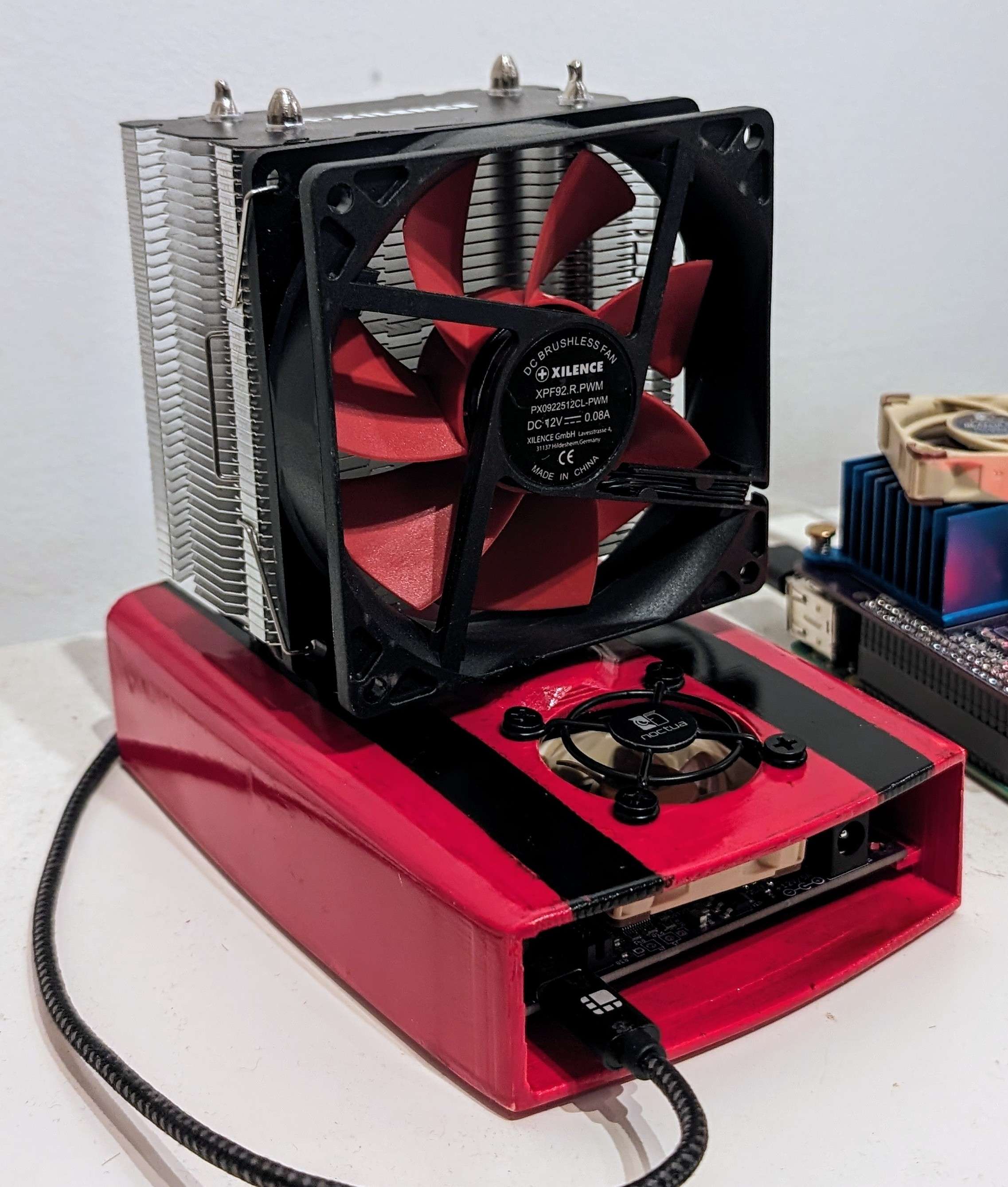
Miniatur-PC mit großem CPU-Kühler
XILENCE XP92.R.PWM DC 12V 0.08A MADE IN CHINA NOCTUA
in „10W Bitcoin miner mit 450GH/s für Raspberry Pi“ · Projekte & Code · · Fotos