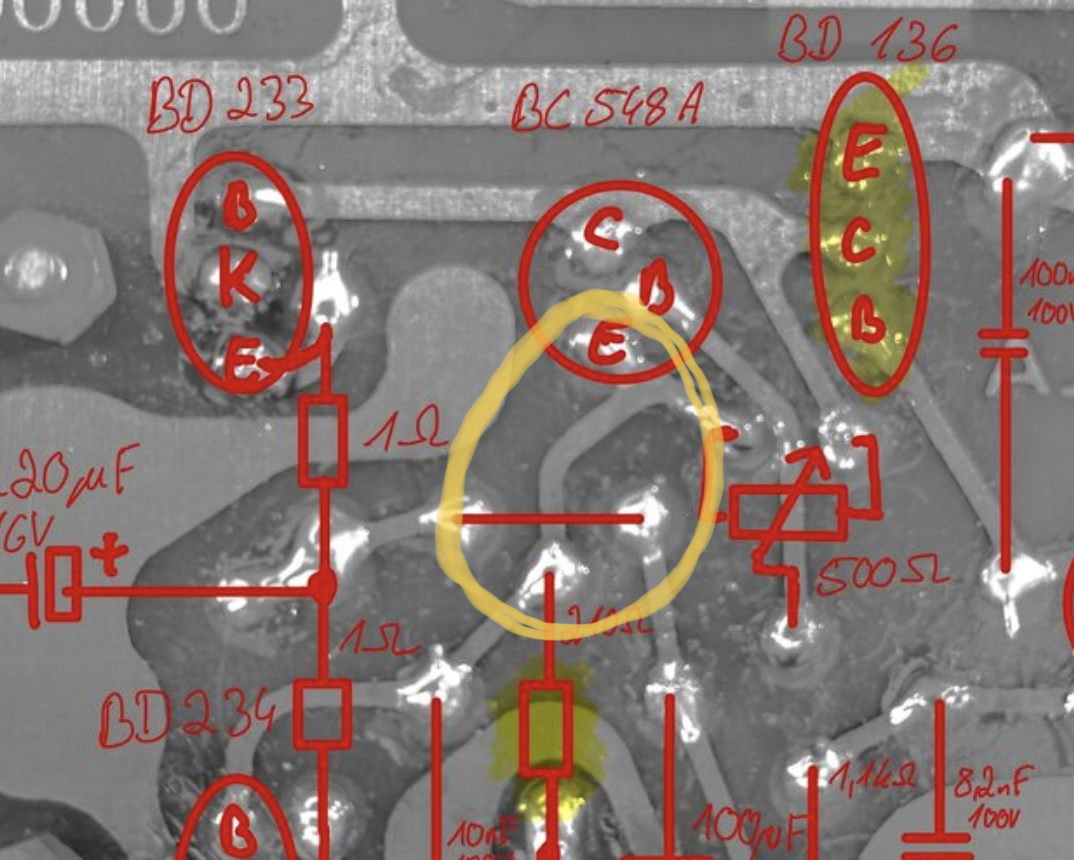
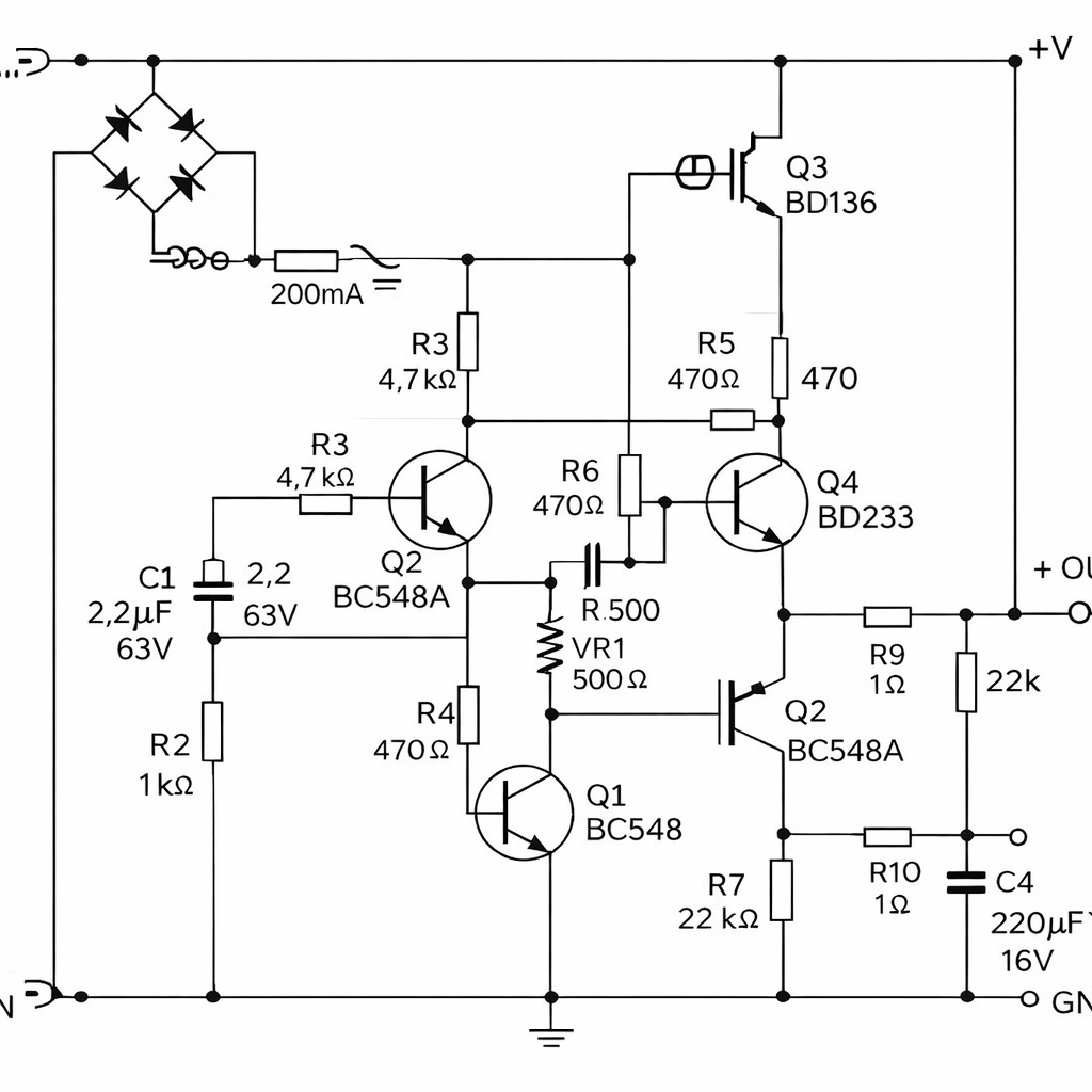
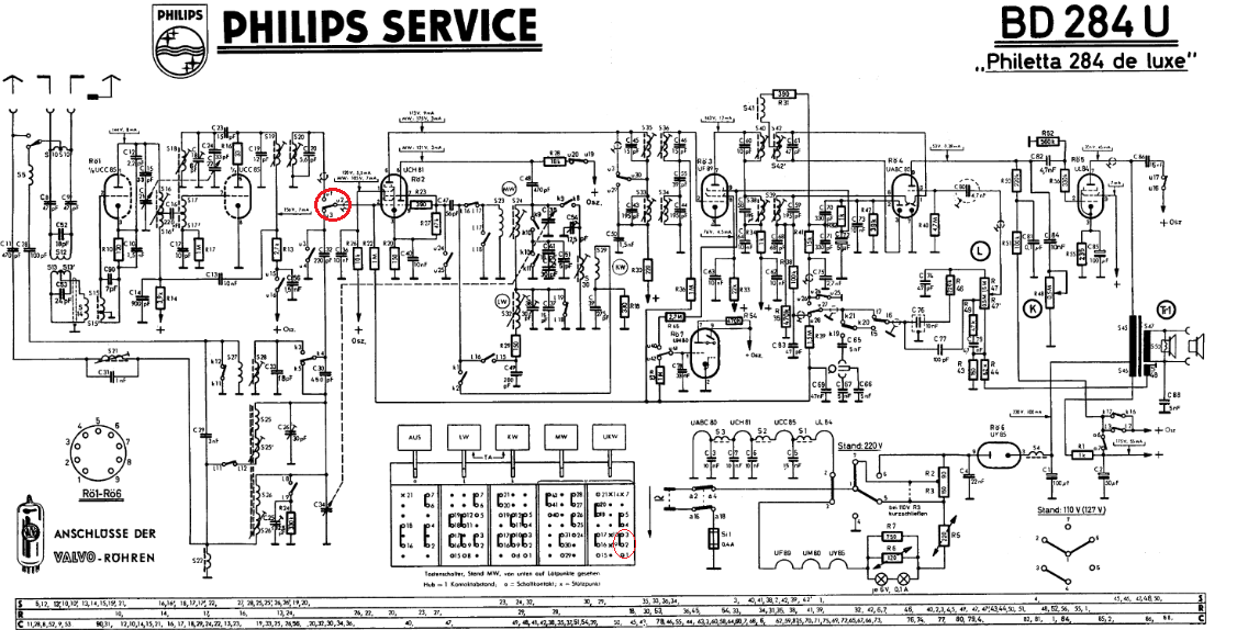
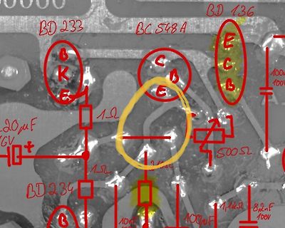
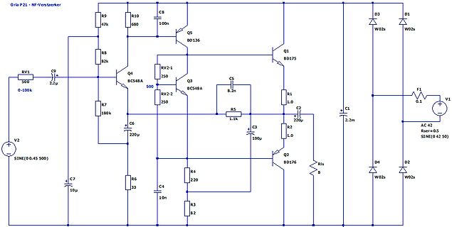
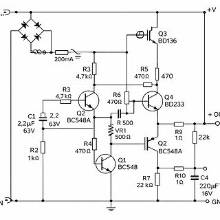
lauten wie folgt: das Bild mit Siebelko oben rechts als Grundlage ist der linke obere Transistor der BD233, der untere BD234 und der rechte mit dem Alustück BD132. Die beiden kleinen sind BC548A. Danke.
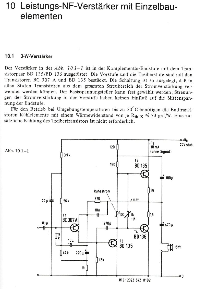
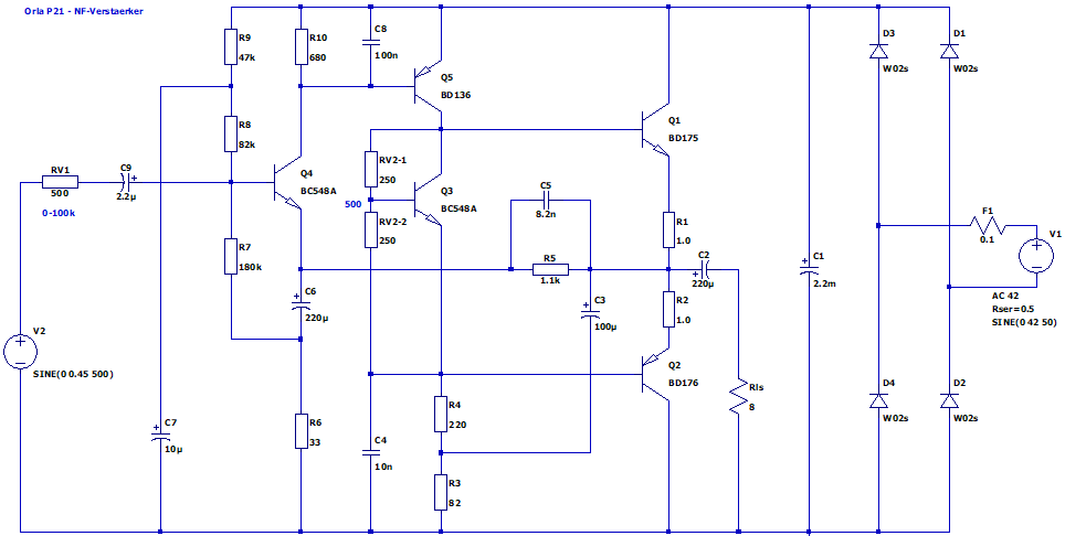
Die Polarität des Ausgangs-Koppelelkos ist wahrscheinlich falsch herum. Der Treibertransistor BD136 hat einen geteilten Arbeitswiderstand am Collector, die 220 und 82 Ohm liegen in Reihe. An deren mittleren Verbindungspunkt liegt der Elko zum Endstufenausgang (noch vor dem Lautsprecher-Elko). Diese
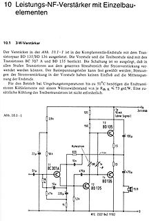
www.ledhilfe.de/viewtopic.php?t=5556 Die andere Lösung verwendet einen Stromspiegel aus zwei Transistoren (BD135, BD136, usw.). https://www.ledstyles.de/index.php?thread/9336-symmetrierung-paralleler-leds-mittels-stromspiegel/
reserved, test signal for production test 1001 reserved 1010 HIGH 1011 LOW 1100 TxActive: at 106 kBd: HIGH during Start bit, Data bit, Parity and CRC at 212 kBd: 424 kBd and 848 kBd: HIGH during data and CRC 1101 RxActive: at 106 kBd: HIGH during Data bit, Parity and CRC at 212 kBd: 424 kBd and 848 kBd: HIGH during data and CRC 1110 subcarrier detected: 106 kBd: not applicable 212 kBd: 424 kBd and 848 kBd: HIGH during last part of data and CRC 1111 test bus bit as defined by the TestSel1Reg register
candidate (partial) keys. If an attacker as many processes as you wish. On an standard quad- gathers136tracesthis allowsher(onaverage)to perform core laptop this computationtakes less than five minutes. 136/4 = 34 bit tests, i.e. just as much as key bits were Therefore,thewholeattackcanbeperformedin less
5 7 ) 9 9 1 5 . R962 3 2 2 R D940 C 0 CY94 9 4 9 PC93 D Q925 0 7 CY92 CY91 R934 Q924 l C C 3 C944 BD95 6 9 C951 e 3 3 4 Q923 PRIMARY 9 9 b 8 7 C C968 BD96 PRIMARY I D 9 a 8 3 C928 C936 L 9 R 9 9 9 9 D D922 e 1 9 L SECONDARY L R C SECONDARY R935 L d 2 9 9 9 o C C C 7 1 6 C 1 PC94 IC98 BD97 c 6 6 6 T
) eff The bias-dependent threshold voltage depends on the bulk-source BSlor the bulk-drain voltage BD depending on the mode of operation. √ √ γ · Φ − VBS − Φ for DS ≥ 0, i.eBSV≥ V BD VTh= V T0+ γ ·√ Φ − V − √Φ for V < 0, i.e. V > V (11.160) BD DS BD BS The following equations describe the DC current
applications Automatic selection of AUI or 10BASET Software selection of AUI or 10BASET ■ Individual 136byte transmit and 128byte receive FIFOs provide packet buffering for ■ Automatic Twisted Pair receive polarity increased system latency, and support the detection and automatic correction of the receive
relative reference function with push button ‘zero set on/off” Reference resistors £80, 75, 93, 110, 125, 136, 150, 250, 300, 500, 600, 800, 900, 1000, 1200, 8000 ohms can be selected with preset k n o b Resolution 01.dBdB for signals < 10mVv Number of representation units £999 for signals < 10 m V Acuracy
o - So - ma o oLI o we o ou o we o wke o wh avoSI o e o oI 2 6» w = bb — to — oD — oD = bb — OD — BD — BD — oD 4 he h e6D ort he ted be cmt the oa he ot be vet he = heD ‘ah6b ot fhe o w u e a e n e w e n e n e wm n e n e a b f e G G G q G G G G a a ees— _ J a « a = = = = = = ae uo = ou Le) vo vu ov
n l s l s c n n s t d l t v s v s i W o e t e m o l e e e e h I t m V t y e - s n s n H s u l e w bd t r . u h u h I i V l l t S a g « i d t d t L c R o o g / s i / c A e A e G t E t t i 8 n s i V e – e + e E i V n n + P/ V - r » i j a » s » S » S e O C C T 1 A s 1 2 3 4 u 1 t r r p a t t e r s e p

 Bild
Bild
 Bild
Bild
 Bild
Bild
 Bild
Bild
 Bild
Bild