-
 Bild
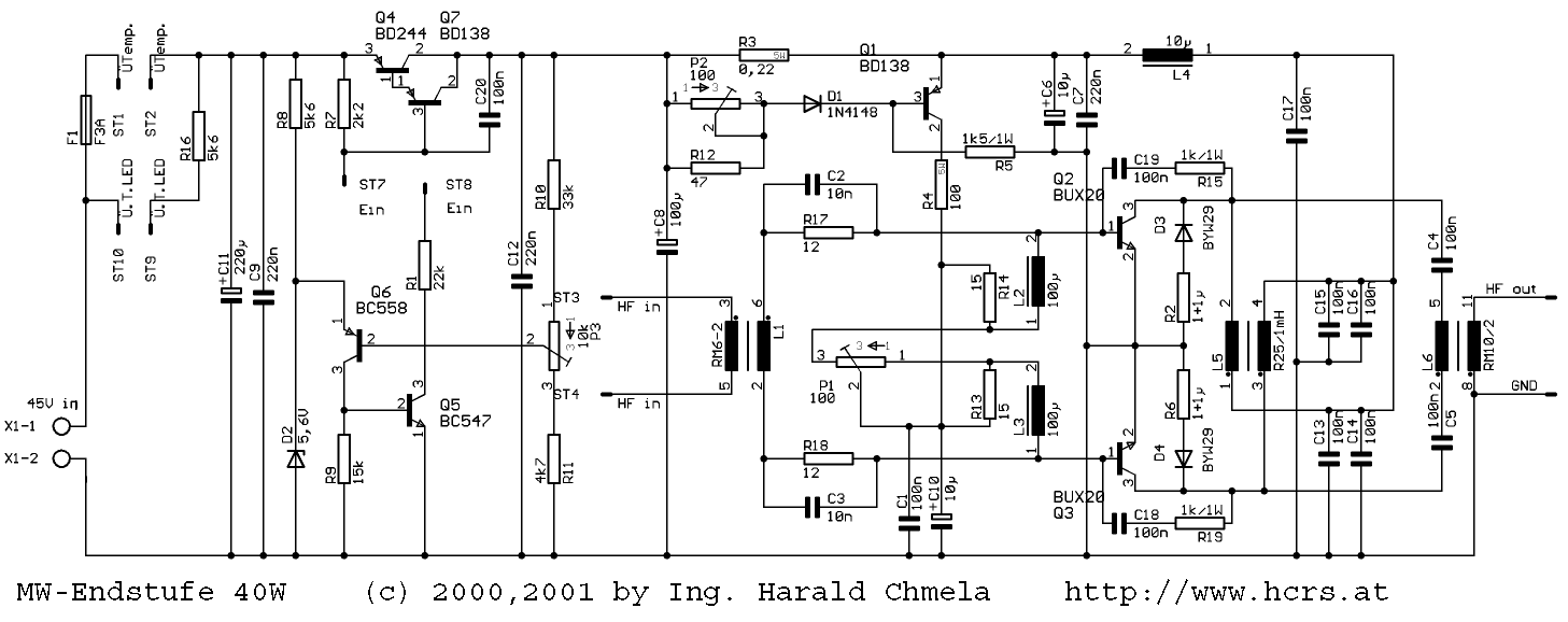
Schaltplan einer 40W MW-Endstufe
, 15k, D2, 5k6, Q5, BC547, R11, 4k7, ST3, ST4, HF in, RM6-2, L1, P3, 10k, C12, 220n, R10, 33k, Q4, BD244, Q7, BD138, P2, 100, D1, 1N4148, R3, R12, 47, C2, 10n, R17, 10u, C6, 10u, C7, 220n, L4, 10u, C17, 100n, Q1, BD138, 1k5/1W, R4, 100, C19, 1k/1W, R15, Q2, BUX20, D3, BU429, C15, 100n, C16, 100n, C4,
in „Wie baut man eine Endstufe für einen Mittelwellensender (160m Band)?“ · HF, Funk und Felder · · Schaltpläne

-
 Bild
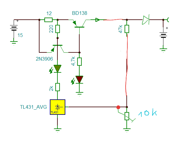
Schaltplan einer Konstantstromquelle oder Spannungsregelung
12 220 BD138 47k 2N3906 4,7k 2k TL431_AVG TL431 10k
in „Motorrad Bleiakku Erhaltungsladung“ · Projekte & Code · · Schaltpläne

-
 Bild
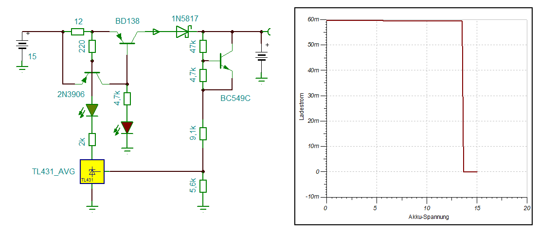
Schaltplan und Diagramm einer Ladestrom-Spannungs-Kennlinie
12 BD138 1N5817 220 4,7k 4,7k BC549C 2N3906 2k 9,1k 5,6k TL431_AVG TL431 60m 50m 40m 30m 20m 10m 0 -10m 0 5 10 15 20 Akku-Spannung Ladestrom
in „Motorrad Bleiakku Erhaltungsladung“ · Projekte & Code · · Screenshots

-
 Bild
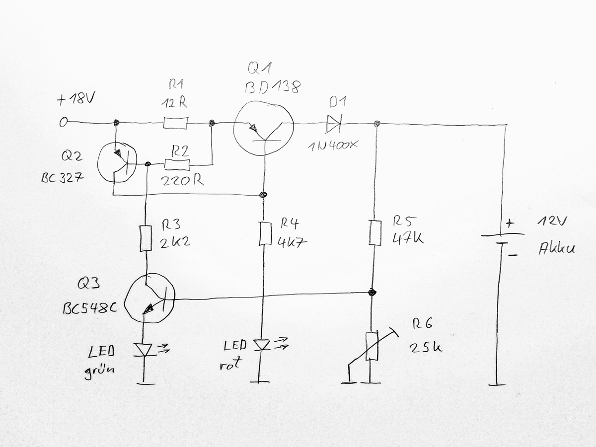
Handgezeichneter Schaltplan einer Schaltung mit Transistoren und LEDs
+18V R1 12R Q1 BD138 D1 1N400X R2 220R Q2 BC327 R3 2K2 R4 4K7 R5 47K + 12V Akku Q3 BC548C R6 25k LED grün LED rot
in „Motorrad Bleiakku Erhaltungsladung“ · Projekte & Code · · Schaltpläne

-
PDF
fsp_technology_fsp202-4fs01_runtkb074wjqz_psu.pdf
QPXFS!TUBHF CVDL D/!TFDPOEBSZ!PVUQVU E!up!E B/!FNJ!GJMUFS!BOE!SBX!C,!DJSDVJU A QPXFS 18V A USBOTGPSNFS BD QGD GVTF FNJ NBJO DPOUUSPM 18V JOQVU GJMUFS SFDUJGJFS DJSDVJU SFDUJGFS!'!DJSDVJU GJMUFS 70V S X P F/GFFE.CBDL!DJSDVJU ! E/PVUQVU!DPOUSPM Y B QXN PQUP.JTPMBUPS ESJWFS DJSDVJU DPOTUBOU!WPMUBHF DJSDVJU
in „Welche Diode ist das?“ · Analoge Elektronik und Schaltungstechnik ·
-
PDF
Datasheet_MFRC522.pdf
reserved, test signal for production test 1001 reserved 1010 HIGH 1011 LOW 1100 TxActive: at 106 kBd: HIGH during Start bit, Data bit, Parity and CRC at 212 kBd: 424 kBd and 848 kBd: HIGH during data and CRC 1101 RxActive: at 106 kBd: HIGH during Data bit, Parity and CRC at 212 kBd: 424 kBd and 848 kBd: HIGH during data and CRC 1110 subcarrier detected: 106 kBd: not applicable 212 kBd: 424 kBd and 848 kBd: HIGH during last part of data and CRC 1111 test bus bit as defined by the TestSel1Reg register
in „IRQ am RFID RC522“ · Mikrocontroller und Digitale Elektronik ·
-
Datei
disassebled_original_working.asm
0f 93 push r16 bc8: 1f 93 push r17 bca: cf 93 push r28 bcc: df 93 push r29 bce: ec 01 movw r28, r24 bd0: 6a 01 movw r12, r20 bd2: 7b 01 movw r14, r22 bd4: a2 2e mov r10, r18 bd6: 8d 89 ldd r24, Y+21 ; 0x15 bd8: 88 23 and r24, r24 bda: 39 f0 breq .+14 ; 0xbea <_ZN9UartClass5beginEmj+0x30> bdc: e8 81 ld
in „Bizarrer Firmware crash - ATmega4808. Wie Debuggen?“ · Mikrocontroller und Digitale Elektronik ·
-
Datei
bat_sensor_0x0d_analysis.html
class="badge-row"> <span class="badge cyan">ESP32-C6 Sniffer</span> <span class="badge amber">LIN 9600 Bd</span> <span class="badge cyan">1614 Frames</span> </div> </div> <div class="stats-row"> <div class="stat s-amber"> <label>Startspannung</label> <span class="val">12.00<span class="unit">V</span></span
in „Reverse Engineering eines LIN Bus“ · Mikrocontroller und Digitale Elektronik ·
-
Datei
disassebled_minimal_change_crash.asm
0f 93 push r16 bc8: 1f 93 push r17 bca: cf 93 push r28 bcc: df 93 push r29 bce: ec 01 movw r28, r24 bd0: 6a 01 movw r12, r20 bd2: 7b 01 movw r14, r22 bd4: a2 2e mov r10, r18 bd6: 8d 89 ldd r24, Y+21 ; 0x15 bd8: 88 23 and r24, r24 bda: 39 f0 breq .+14 ; 0xbea <_ZN9UartClass5beginEmj+0x30> bdc: e8 81 ld
in „Bizarrer Firmware crash - ATmega4808. Wie Debuggen?“ · Mikrocontroller und Digitale Elektronik ·
-
Datei
utf8_demo.c
0xC3,0xA7,0x00, // ASCII-135 0xC3,0xAA,0x00, // ASCII-136 0xC3,0xAB,0x00, // ASCII-137 0xC3,0xA8,0x00, // ASCII-138 0xC3,0xAF,0x00, // ASCII-139 0xC3,0xAE,0x00, // ASCII-140 0xC3,0xAC,0x00, // ASCII-141 0xC3,0x84,0x00, // ASCII-142 0xC3,0x85,0x00, // ASCII-143 0xC3,0x89,0x00, // ASCII-144 0xC3,0xA6,0x00, // ASCII
in „Cursorpositionierung, Farben und Codepage 437 Ausgabe im Linuxterminakl“ · Projekte & Code ·
-
Datei
fontandcolor.h
0x1C9F // 30, 144, 255 #define COLOR_DEEPSKYBLUE 0x05FF // 0, 191, 255 #define COLOR_CORNFLOWERBLUE 0x64BD // 100, 149, 237 #define COLOR_SKYBLUE 0x867D // 135, 206, 235 #define COLOR_LIGHTSKYBLUE 0x867F // 135, 206, 250 #define COLOR_LIGHTBLUE 0xAEDC // 173, 216, 230 #define COLOR_POWDERBLUE 0xB71C // 176
-
Datei
SMY202.HEX.txt
20BCC000FFFFFFFFFFFFFFFFFFFFFFFFFFFFFFFFFFFFFFFFFFFFFFFFFFFFFFFFFFFFFFFF84 :20BCE000FFFFFFFFFFFFFFFFFFFFFFFFFFFFFFFFFFFFFFFFFFFFFFFFFFFFFFFFFFFFFFFF64 :20BD0000FFFFFFFFFFFFFFFFFFFFFFFFFFFFFFFFFFFFFFFFFFFFFFFFFFFFFFFFFFFFFFFF43 :20BD2000FFFFFFFFFFFFFFFFFFFFFFFFFFFFFFFFFFFFFFFFFFFFFFFFFFFFFFFFFFFFFFFF23 :20BD4000FFFFFFFFFFFFFFFFFFFFFFFFFFFFFFFFFFFFFFFFFFFFFFFFFFFFFFFFFFFFFFFF03 :20BD6000FFFFFFFFFFFFFFFFFFFFFFFFFFFFFFFFFFFFFFFFFFFFFFFFFFFFFFFFFFFFFFFFE3 :20BD8000FFFFFFFFFFFFFFFFFFFFFFFFFFFFFFFFFFFFFFFFFFFFFFFFFFFFFFFFFFFFFFFFC3 :20BDA000FFFFFFFFFFFFFFFFFFFFFFFFFFFFFFFFFFFFFFFFFFFFFFFFFFFFFFFFFFFFFFFFA3
in „[V] Rohde und Schwarz SMY02 9kHz-2.080Gh Signal Generator“ · Markt ·
-
PDF
pm2521ocr.pdf
?®D 6 e l&f -ew o e s . o) : = 2 O p t @ O y o p r & ” O p e + S ag @® o p r : ® £~ 2S £r e =S ~~ BD erC F / S ep Y oS C A 8 | P S e r Fg = : a H a n ® H a d ® B E A L E 2 | A B H L E YS | H O H S £ o O ANH os ; x 2 2 8 = — P= © = a) st 5 oc on & 2 o — band - Lu aed i =) e E cc3so 3 : 2< =e) =° S 6
in „Pjilips PM2519“ · Markt ·
-
PDF
grip1.pdf
von Joysticks o.a. frei. Da die Baudrate von seriellen Tastatu- ren ziemlich niedrig ist (i.a. 600 Bd), kann die Seriell-parallel- Wandlung von der CPU, d.h. per Software, übernommen werden. Timer A erzeugt hierfür den Baudratentakt durch periodische Interrupts. Für eine IBM-kompatible serielle Tastatur
in „Conitec PROF-80 Informationsseite“ · Mikrocontroller und Digitale Elektronik ·
-
PDF
pm2534ocr.pdf
o - So - ma o oLI o we o ou o we o wke o wh avoSI o e o oI 2 6» w = bb — to — oD — oD = bb — OD — BD — BD — oD 4 he h e6D ort he ted be cmt the oa he ot be vet he = heD ‘ah6b ot fhe o w u e a e n e w e n e n e wm n e n e a b f e G G G q G G G G a a ees— _ J a « a = = = = = = ae uo = ou Le) vo vu ov
in „Pjilips PM2519“ · Markt ·
-
Datei
fritzbox_7590_log.txt
NMI-Watchdog-Reset(NMI) - NMI(3)UP(44)UTC(44)FW(08.20)HW(226)HWS(4)BV(1.3578)BN(122916)FS(08.20)BT(1)BD(0) [ 44.711494][ C1] CPU1 NMI taken (err)epc=0x93d352f8 __udelay+0x48/0x58 [#1]: [ 44.718387][ C1] CPU: 1 PID: 1482 Comm: modprobe Tainted: P O 4.9.337 #1 [ 44.726452][ C1] task: 9e25ae60 task.stack:
in „FritzBox 7590 Boot Loop“ · Mikrocontroller und Digitale Elektronik ·
-
PDF
pm2519ocr.pdf
300, 500, 600, 800, 900, 1000, 1200, 8000 ohms can be selected with preset k n o b Resolution 01.dBdB for signals < 10mVv Number of representation units £999 for signals < 10 m V Acuracy +Signals >10mV:0.2dB Signals < 1 0 m V : 1dB Temperature coefficient £0,013 dB/°C. Input impedance 110 M Q + 1 %
in „Pjilips PM2519“ · Markt ·
-
PDF
am79c961.pdf
to pins XTAL1 and XTAL2. Alternatively, an external 20 MHz CMOScompatible clock signal can be 1 SF/BD used to drive this pin. Refer to the section on External 2 SRD Crystal Characteristics for more details. 3 SRDCLK XTAL2 Crystal Connection Output The internal clock generator uses a 20 MHz crystal that
-
PDF
Elektor_1978-06.pdf
The two-stage transis- toramplifier consisting of T27 and T28 provides a gain of around 60. After BD242 being amplified, the high frequency input signal is fed to the decade divider, IC24. This is an ECL (emitter-coupled logic) device, which can operate at the very high frequencies involved. The Figure
-
PDF
grundig32zollLedTV.pdf
n l s l s c n n s t d l t v s v s i W o e t e m o l e e e e h I t m V t y e - s n s n H s u l e w bd t r . u h u h I i V l l t S a g « i d t d t L c R o o g / s i / c A e A e G t E t t i 8 n s i V e – e + e E i V n n + P/ V - r » i j a » s » S » S e O C C T 1 A s 1 2 3 4 u 1 t r r p a t t e r s e p
in „Reparaturbericht LED-TV Grundig 32 VLE 5620 BN Ton gut, aber kein Bild“ · Analoge Elektronik und Schaltungstechnik ·
-
PDF
Sartorius_Waage_Manual_Anleitung_Handbuch_QC7DCE-S.pdf
2-line header and ID label” 1012 “Sartorius QC Series Counting Scale with PC Connecting Cable (1200Bd,O,7,1)” 1013 INPUT “Your PC interface, i.e. COM1or COM2 (enter1or 2)”; a 1015 IF a = 1 THEN OPEN “com1:1200,o,7,1,CS1000,DS0,CD0,PE” FOR RANDOM AS #1 1016 IF a = 2 THEN OPEN “com2:1200,o,7,1,CS1000,DS0
in „Frage zu einer Waage / Sartorius QC7DCE-S“ · Mechanik, Gehäuse, Werkzeug ·
-
PDF
AM700_SM.pdf
sources which are also supplied to the Digital Audio board. A +5 V reference source is developed by U138. This reference is used to produce two difference reference levels to the A/D converter, U124, that is part of the Eye Sampler circuit, shown in diagram 11. 3–26 AM700 Audio Measurement Set Service
in „Tektronix AM700“ · Mikrocontroller und Digitale Elektronik ·