-
 Bild
Screenshot eines BLE-Doorlock Server Log-Fensters
192.168.0.242 BLE-Doorlock Server — Logs Dashboard Settings Registration Total: 10 OK: 10 Retried: 0 Failed: 0 Auto: 10 HTTP: 0 Conflicts: 1 Rescued: 1 Avg: 22s Min: 20s Max: 36.6s Connected Debug Copy Clear 19:54:26 [INFO] werkzeug: 192.168.0.163 - - [09/May/2026 19:54:26] "GET /stats HTTP/1.1" 200 - 19:54:26 [INFO] werkzeug: 192.168.0.163 - - [09/May/2026 19:54:26] "GET /logs/stream HTTP/1.1" 200 -
in „Software zum Steuern des Türschlossantrieb "eqiva eQ-3 Bluetooth Smart Lock"“ · Projekte & Code · · Screenshots

-
Datei
260503_OllamaInterface.html
Web Interface</title> <style> body { font-family: 'Segoe UI', Tahoma, Geneva, Verdana, sans-serif; max-width: 800px; margin: 0 auto; padding: 20px; background-color: #f5f5f5; color: #333; } .container { background-color: white; border-radius: 10px; padding: 25px; box-shadow: 0 4px 12px rgba(0,0,0,0.1
-
 Bild
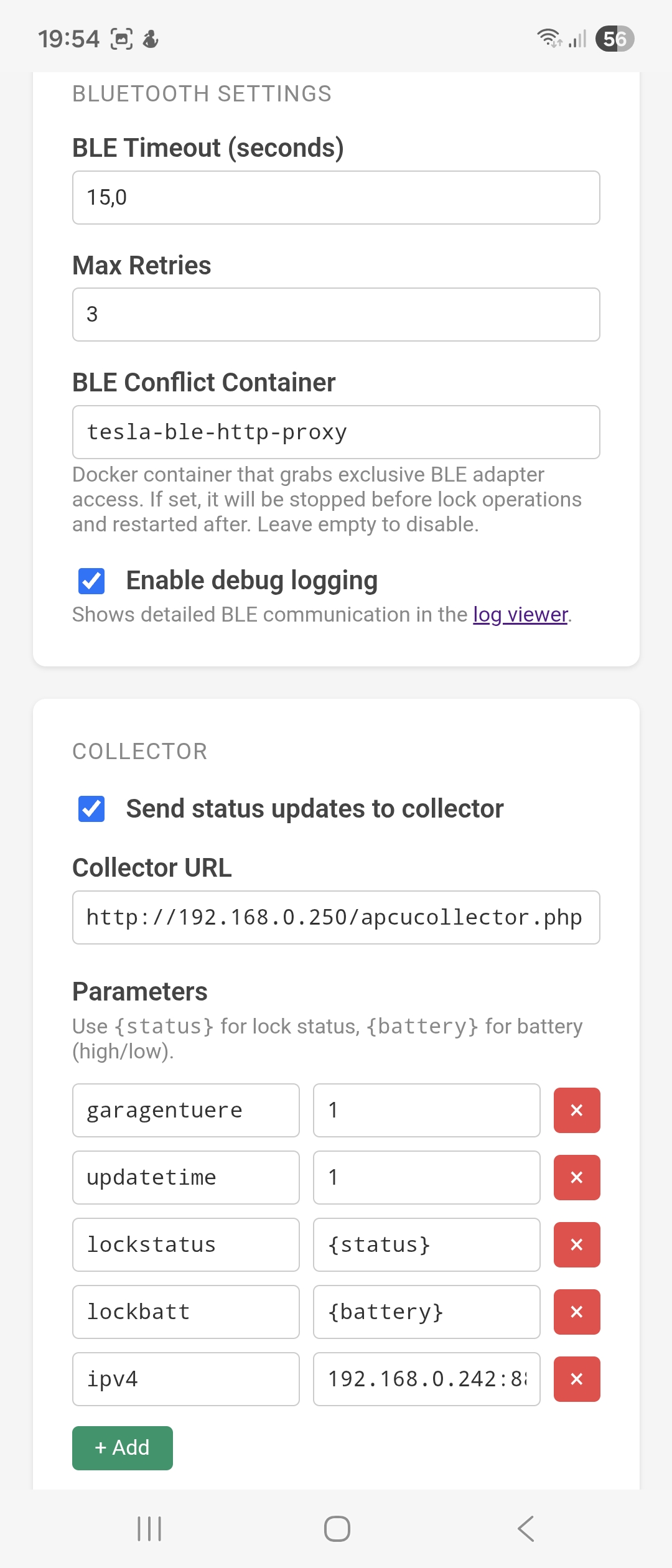
Einstellungen einer Software für BLE und Collector-Datenübertragung
19:54 BLE SETTINGS BLE Timeout (seconds) 15,0 Max Retries 3 BLE Conflict Container tesla-ble-http-proxy Docker container that grabs exclusive BLE adapter access. If set, will be stopped before lock operations and restarted after. Leave empty to disable
in „Software zum Steuern des Türschlossantrieb "eqiva eQ-3 Bluetooth Smart Lock"“ · Projekte & Code · · Screenshots
-
PDF
ch9121.pdf
CLIENT mode by default. The default parameters related to the network are as follows: (1) Device IP: 192.168.1.200 (2) Subnet mask: 255.255.255.0 (3) Default gateway: 192.168.1.1 (4) Module port: 2000 (5) Destination IP: 192.168.1.100 (6) Destination port: 1000 (7) Number of reconnection: unlimited UART
in „Serieller Tunnel durch IP-Netz?“ · Mikrocontroller und Digitale Elektronik ·
-
Datei
Messung_der_Spannung_eines_48V_LiFePO4-Akkus_an_seinen_Polklemmen_v1.1.ino
45V) #define UB_HYSTERESE 35 // ADC-Inkremente für Hystereseschwelle (ca. 2V) #define ANZ_ADC_EVAL 192 // Anzahl ADC-Messungen zur Bestimmung der ADC-Min-Max-Werte über eine volle 50 Hz Netzperiode // ANZ_ADC_EVAL = 125000 Hz ADC-Frequenz / 13 ADC-Takte pro ADC-Messung / 50 Hz Netzfrequenz #define ENTPRELL_LIM
in „avr adc streuung ausgleichen“ · Mikrocontroller und Digitale Elektronik ·
-
Datei
Logo-lesen.ino
Siemens LOGO! 8 FS4 ============================================================ LOGO! IP-Adresse: 192.168.0.99 LOGO! Variable: VW0 S7-Adresse: DB1.DBW0 Kommunikation: S7 / ISO-on-TCP TCP Port 102 Rack 0 Slot 2 ESP32: Asynchroner Webserver Automatische LOGO!-Wiederverbindung VW0 wird alle 500 ms gelesen
in „mit ESP32 LOGO 8 VM Block lesen“ · Mikrocontroller und Digitale Elektronik ·
-
PDF
trafo_datasheet.pdf
control and could cause personal injury or NOTE: property damage. 1. All leads 8" long minimum. D D MAX. MAX. 2 H MAX. H R z 2 MW MAX. O X 6 1 1 W C X R5 MAX. N P P7 T 1 S .188 ± .015 DIA. (2 HOLES) STYLE A 1 3 MD MW W MAX. PRIMARY SECONDARY 117V, 50/60 Hz 4 24V CT MS (4 PLACES) STYLE NV 2 5 SCHEMATIC
in „[V] Trafo, Gleichrichter, Elko für 115V/24V 12A Netzgerät“ · Markt ·
-
PDF
Operationsverstaerker_Auswahl.pdf
Geeignete bzw. passende Typen wären beispielsweise: MCP6022 (Rail-to-Rail, 2,8 MHz, 7 V/µs, allerdings max. 6 V Versorgung → nicht geeignet für ±15 V) OPA197 – passt sehr gut: Versorgung: ±2,25 V bis ±18 V Rail-to-Rail-Ausgang GBW: 10 MHz Slew Rate: 20 V/µs OPA192 Versorgung bis ±18 V Rail-to-Rail Ein- und
in „Suchmaschine für Halbleiter gesucht“ · Analoge Elektronik und Schaltungstechnik ·
-
Datei
pulse_spm2007_44.txt
Package Pulse Part Number Inductance @ Irated (µH) Irated (A) DCR Typ (mΩ) DCR max (mΩ) Inductance @ 0ADC (µH) Reference ET (Volt-µsec) Flux Density Factor (K1) Core Loss Factor (K2) Temp. Rise Factor (K3) Package Pulse Inductance Irated DCR DCR Inductance Reference Flux Density Core Loss Temp. Rise Part @ Irated TYP MAX @ 0ADC ET Factor Factor Factor Number (µH) (A) (mΩ) (mΩ) (µH) (Volt-µsec) (K1) (K2) (K3) CI-20 PE-53630NL 1,01 3,40 9,35 11 1,1 0,53 5,43 3,29E-11 323,9 CI-20 PE-53600NL 6,2 1,40 59,5 70 7 1,33 2,17
in „[V]SMT Power Inductors“ · Markt ·
-
PDF
W5500_ds_v110e.pdf
Tolerance (at 25℃) ±30 ppm Shunt Capacitance 7pF Max Drive Level 59.12uW Load Capacitance 18pF Aging (at 25℃) ±3ppm / year Max 60 / 67 W5500 Datasheet Version1.1.0 5.5.4 SPI Timing TCS VIH SCSn VIL TCSS TCSH VIH SCLK V TWH TWL IL TDSTDH V IH MOSI VIL
in „Schaltung W5500“ · Mikrocontroller und Digitale Elektronik ·
-
PDF
40146F.pdf
0°C to +70°C Industrial(I):Tamb = -40°C to BSEL = 0 BSEL = 1 +85°C Symbol Characteristic Min Typ. Max. Min. Typ. Max. Units TE Basic pulse element 260 400 620 130 200 310 μs TBP PWM bit pulse width 3 3 TE TP Preamble duration 28 28 TE TS Sync Pulse duration 10 10 TE TH Header duration 10 10 TE THOP
in „Fehlersuche Funksender Zentralverriegelung Toyota Yaris“ · Fahrzeugelektronik ·
-
Datei
main.txt
=========== GLOBALE VARIABLEN ==================== current_pwm = PWM_MAX target_pwm = PWM_MAX ramp_start_time = None ramp_start_value = None last_boost_start = 0 boost_active = False timers = [] client = None # GLOBALE VARIABLEN FÜR PIN 5 FLANKENMESSUNG last_pin5_time_us
in „PWM Webrowser Pumpenmonitor / Steuerung“ · Mikrocontroller und Digitale Elektronik ·
-
PDF
lnix-s-a0001298418-1.pdf
and configuration screens • Interactive web pages through the use of Java applets • E-mail • 128-, 192-, or 256-bit AES Rijndael encryption (Optional) • EMI tested and compliant • Extended operating temperature: -40 to +85˚ C normal mode -40 to +75˚ C high-performance mode • High-performance processor
in „[V] 1Stück gebrauchtes XPORT-EDGE_Seriell- LAN Modul (12€)“ · Markt ·
-
PDF
lnix-s-a0001298418-1.pdf
and configuration screens • Interactive web pages through the use of Java applets • E-mail • 128-, 192-, or 256-bit AES Rijndael encryption (Optional) • EMI tested and compliant • Extended operating temperature: -40 to +85˚ C normal mode -40 to +75˚ C high-performance mode • High-performance processor
in „[V] 1Stück neues Lantronix_XPORT_Seriell- LAN Modul (18€)“ · Markt ·
-
 Bild
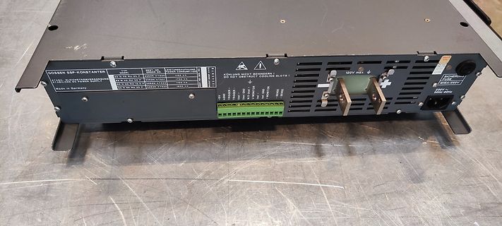
Rückseite eines Gossen stabilisierten Stromversorgungsgeräts
LEISTUNSAUFNAHME POWER CONSUMPTION 1750 VA 1850 VA KÜHLUNG NICHT BEHINDERN! DO NOT OBSTRUCT COOLING SLOTS! 120V max. SICHERUNG FUSE 230V 50Hz-60Hz +15V TRIGGER + TRIGGER - +5V +12V +24V +48V +144V +192V +240V TENSE + TENSE -
in „(V) Gossen Konstanter SSP 62 N 40 RU 50 P Netzteil“ · Markt · · Fotos
-
 Bild
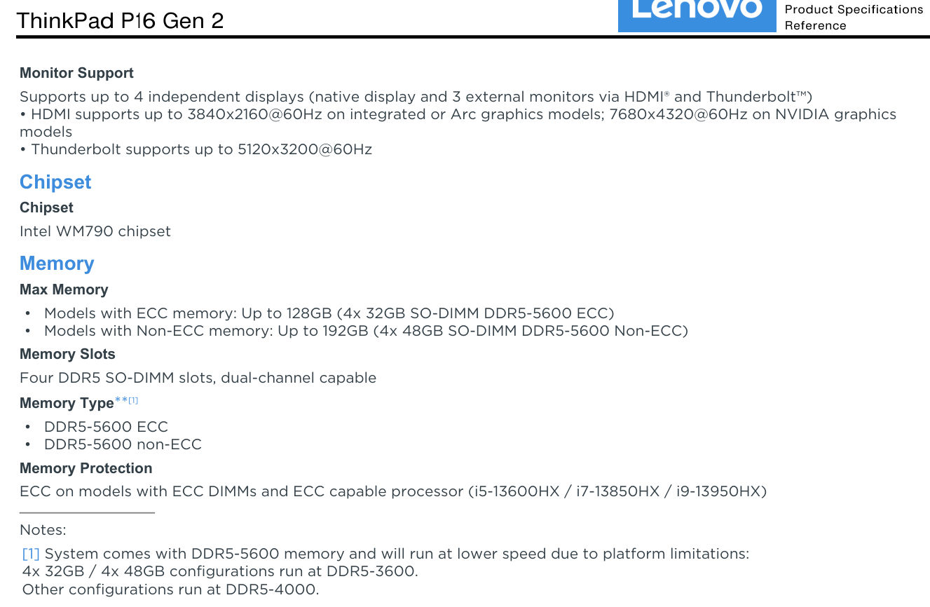
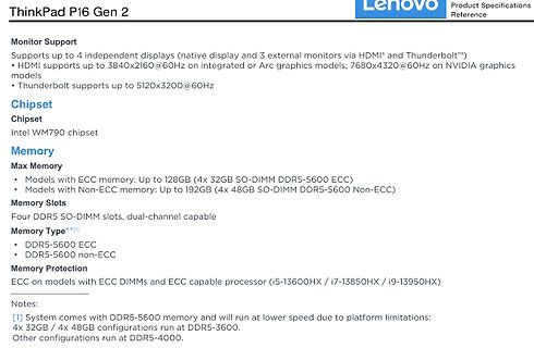
Produktspezifikationen ThinkPad P16 Gen 2
NVIDIA graphics models • Thunderbolt supports up to 5120x3200@60Hz Chipset Intel WM790 chipset Memory Max Memory • Models with ECC memory: Up to 128GB (4x 32GB SO-DIMM DDR5-5600 ECC) • Models with Non-ECC memory: Up to 192GB (4x 48GB SO-DIMM DDR5-5600 Non-ECC) Memory Slots Four DDR5 SO-DIMM slots, dual-channel
in „Lenovo ThinkPad-P16-G2 - RAM erweitern von 64 auf 128 GB“ · PC Hard- und Software · · Screenshots
-
Datei
usb.c
double words = 64 bytes, so we have 400+64 bytes in total. */ #define USB_RAM 0x40006000 #define EpCtrlMaxLen 64 #define EpCtrlLenId ((1<<15)|(1<<10)) #define EpBulkMaxLen 64 #define EpBulkLenId ((1<<15)|(1<<10)) #define EpIntMaxLen 8 #define EpIntLenId (4<<10) // EP0 = control #define Ep0TxOffset 0 // 64
in „STM32G484 USB CDC Code läuft nur wenn mit <= -O1 kompiliert“ · Mikrocontroller und Digitale Elektronik ·
-
PDF
SAA7220.PDF
, SAA7220 and 16-bit dual DAC (TOA1541) QUICK REFERENCE DATA parameter conditions symbol min. typo max. unit 4,5 5,0 5,5 V Supply voltage (pin 24) VOO Supply current (pin 24) 100 100 180 285 rnA Input voltage ranges WSAB,OAAB,EFAB,SOAB note 2 CLAB, SCAB, ATSB, MUSB note 3 Input voltage LOW note 1 VIL
in „Hilfe: Takt Mission (Philips) CD-Player fällt aus“ · Analoge Elektronik und Schaltungstechnik ·
-
PDF
Anleitung-Eurolite-SL-1200-search-light-de_en_es_fr.pdf
SFc-15 400h No. 89302005 OSRAM HMI 1200/GS 100V/1200W SFc-15.5 No. 89302010 EUROLITE DMX operator 192 channels No. 70064520 EUROLITE DMX scan control 192 channels No. 70064525 FUTURELIGHT EX-6/32 controller No. 51834046 FUTURELIGHT CP-240 controller No. 51834265 Wizard-512 USB DMX software + interface
in „Eurolite SL-1200: Thermische Abschaltung nach 10 min (HMI-Lampe)“ · Analoge Elektronik und Schaltungstechnik ·
-
PDF
100807728a.pdf
per hour Wet bulb temperature 37.7°C max (operating) 40.0°C max (non-operating) Altitude, operating –304.8 m to 3048 m (–1000 ft to 10,000+ ft) Altitude, non-operating –304.8 m to 12,192 m (–1000 ft to 40,000+ ft) (below mean sea level, max
in „Komponenten für Low Power Fileserver?“ · PC Hard- und Software ·
-
Datei
Rep600_fail_blinktgruen.txt
775.000MHz, DDR:650.000MHz, AHB:258.333MHz, Ref:25.000MHz [ 0.000000] clocksource: MIPS: mask: 0xffffffff max_cycles: 0xffffffff, max_idle_ns: 4932285024 ns [ 0.000007] sched_clock: 32 bits at 387MHz, resolution 2ns, wraps every 5541893118ns [ 0.219148] console [ttyS0] enabled [ 0.222771] Calibrating delay
in „AVM Fritz Repeater 600 - fehlgeschlagenes Firmware Update?!“ · Mikrocontroller und Digitale Elektronik ·
-
PDF
T6963C.pdf
LINES 2 4 6 8 10 12 14 16 4 8 12 16 20 24 28 32 V−DOTS 16 32 48 64 80 96 112 128 32 64 96 128 160 192 224 256 1 SCREEN 2 SCREENS MD2 H L H L MD2 Input Pins for selection of number of columns MD3 H H L L MD3 Columns 32 40 64 80 FS0 H L H L FS0 FS1 H H L L FS1 Input Pins for selection of font Font 5 ×
in „altes Phytec MCB-51 Monitor/Basic Befehle?“ · Mikrocontroller und Digitale Elektronik ·
-
PDF
20240122_Waasner_Katalog.pdf
aus der nachstehenden For details please refer to the following checklist: Bandbreite: min. 10 mm max. 400 mm Strip width: min. 10 mm max. 400 mm Checkliste: Streifenlänge: min. 20 mm max. 3000 mm Strip length: min. 20 mm max. 3000 mm Lochdurchmesser min. 4,5 max. 28 mm Hole diameter: min. 4.5 mm max. 28 mm Bandbreite: min. 10 mm max. 400 mm Strip width: min. 10 mm max. 400 mm AnzahStreifenlänge: enen Lmin. 20 mm ser: max. 3000 mmmax. 3 NumbStrip length: t diamemin. 20 mm max. 3000 mm max. 3 Materialstärke 0,27 / 0,30 / 0,35 / 0,50
in „Was ist aus dem Transduktor geworden?“ · Analoge Elektronik und Schaltungstechnik ·
-
PDF
217369.pdf
, y a PARTNUMBER/STANDARDCONFIGURATIONS W a Numberof “A” “B” “C” y (10,16) “A” PartNumber Contacts Max. Max. Max. R Max. Max. 1.100 .900 .700 3 514-AG21D 14 (27,49) (22,86) (17,78) 2 . 1.220 1.010 .800 n “C” (2,54) “B” 516-AG21D 16 (30,99) (25,65) (20,32) , Max. Typ. Max. g r e i Note: Before ordering
in „Kühlkörper TO3 Befestigungslöcher zu groß?“ · Mechanik, Gehäuse, Werkzeug ·
-
PDF
3265fa.pdf
25°C(Note2). V =V =EN =EN =10V, MODE=0V, R =200kΩ A IN_P IN_N T SYMBOL PARAMETER CONDITIONS MIN TYP MAX UNITS Boost Charge Pump VIN_P VIN_PInput Voltage Range l 4.5 16 V VUVLO VIN_PUndervoltage Lockout Threshold VIN_PRising l 3.8 4 V VIN_PFalling l 3.4 3.6 V I V Quiescent Current Shutdown, EN = EN = 0V
in „einfache, kostengünstige Erzeugung einer symmetrischen Spannungsversorgung bei geringer Leistung“ · Analoge Elektronik und Schaltungstechnik ·
-
PDF
Pt100-Vierleiter-Verdrahtungsdiagnose.pdf
Ablauf, Schwellen ADC ADS1220 oder ADS124S08 24-bit, optional 2× IDAC intern IDAC REF200, Howland (OPA192 + 2,49 kΩ) oder ADC-IDAC 1 mA, umkehrbar Mux 3× TMUX1134 oder 1× ADG1414 Quelle, Rückführung, Sense A/B INA INA333 V_sense, hohe Gleichtaktunterdrückung Schutz 100 Ω + SMAJ5.0A + BAT54S je Ader ESD,
in „ESP 32 oder Nano“ · Mikrocontroller und Digitale Elektronik ·
-
PDF
DS_DA221.pdf
Component Level Tests Test Condition Qty/lot Lot Acc/Rej Result Preconditioning(MSL3) 24hrs HTSL (125C) ->192Hrs WHTSL 77 3 0/1 PASS (30C/60%RH) + 3x PbFree Reflow, 260C max JEDEC JESD22-A113F Temperature Cycle* -40C~85C (air to air) 500 cycles 77 3 0/1 PASS JEDEC JESD22-A104D Condition N Shock Test 10000G/
in „Seltsames Verhalten eines Beschleunigungssensors“ · Mikrocontroller und Digitale Elektronik ·
-
PDF
device.pdf
No Need WAMACH5 V5.04 AMD PLD MACH5-128/68 ADP-MACH5-Q100/TQ100 No Need WAMACH5 V5.04 AMD PLD MACH5-192/104 ADP-MACH5-Q144 No Need WAMACH5 V5.04 AMD PLD MACH5-192/120 ADP-MACH5-Q160 No Need WAMACH5 V5.04 AMD PLD MACH5-192/160 ADP-MACH5-Q208 No Need WAMACH5 V5.04 AMD PLD MACH5-192/68 ADP-MACH5-Q100/TQ100
-
PDF
TM56E6422-tenxtechnology.pdf
error. The EEPROM Write usage is similar to read EEPROM. When F/W writes data to the register EEPDT (192h), the data will also be written to EEPROM. EEPROM writing requires max 10ms@V =3CC 2ms@V =CC. This Chip has a build-in EEPROM Time-out function for escaping write fail state. EEPROM writing needs V
in „MCU identifikation/Datenblatt - MC9989A0ZQ“ · Mikrocontroller und Digitale Elektronik ·
-
PDF
HD66766R.PDF
191 COM92 9155 729 271 SEG360 6156 1145 351 SEG280 3116 1145 32 VCI2 -5376 -1168 112 VSH 5111 -1168 192 COM94 9155 767 272 SEG359 6118 1145 352 SEG279 3078 1145 33 VCI2 -5276 -1168 113 VOUT 5291 -1168 193 COM96 9155 805 273 SEG358 6080 1145 353 SEG278 3040 1145 34 VCI2 -5176 -1168 114 VOUT 5391 -1168
in „LCD-Modul F51661GNCJU-MLW-AA * Info *“ · Mikrocontroller und Digitale Elektronik ·
-
PDF
M48T58Y.pdf
parameters M48T58, M48T58Y Table 10. Power down/up AC characteristics (1) Symbol Parameter Min Max Unit tPD E1 or W at VIHor E2 at ILbefore power down 0 µs (2) tF VPFD (max) to VPFD (min) VCC fall time 300 µs (3) M48T58 10 µs tFB VPFD (min) to SS V CC fall time M48T58Y 10 µs t V (min) to V (max) V rise time 10 µs R PFD PFD CC t V to V (min) V rise time 1 µs RB SS PFD CC trec VPFD (max) to inputs recognized 40 200 ms 1. Valid for ambient operating temperaAure: T = 0 toCC0= 4.75 to 5.5 V or 4.5 to 5.5 V (except where noted). 2. V PFD(max) to PFD(min) fall time of lessFthan t may result
in „[S] DALLAS DS1220Y-150 NVRAM (NOS)“ · Analoge Elektronik und Schaltungstechnik ·
-
Datei
Lambdacontroller_ai_claude_2.ino
int serial_counter = 0; uint16_t CJ125_Status = 0; // PID int dState = 0; int iState = 0; const int iMax = 250; const int iMin = -250; const float pGain = 120.0; const float iGain = 0.8; const float dGain = 10.0; // ----------------------------- // Lambda- und O2-Tabellen (Platzhalter) // -------------
in „Bosch CJ125 mit AVR AT90CAN64“ · Mikrocontroller und Digitale Elektronik ·
-
Datei
Lambdacontroller_ai_claude.txt
int serial_counter = 0; uint16_t CJ125_Status = 0; // PID int dState = 0; int iState = 0; const int iMax = 250; const int iMin = -250; const float pGain = 120.0; const float iGain = 0.8; const float dGain = 10.0; // ----------------------------- // Lambda- und O2-Tabellen (Platzhalter) // -------------
in „Bosch CJ125 mit AVR AT90CAN64“ · Mikrocontroller und Digitale Elektronik ·
-
PDF
ISL88731.PDF
, F is the Acknowledge. The master then sends the higher data byte to be IN,MAX SW written into the desired register. The ISL88731 will respond with switching frequency and I L,MAX is the max DC current in the an Acknowledge. The master then issues a Stop condition, inductor. indicating to the ISL88731 that the current transaction is For VIN,MAX = 20V, VBAT = 12.6V, IBAT,MAX = 4.5A, and complete. Once this transaction completes the ISL88731 will fs= 400kHz, the calculated inductance is 9.3µH. Choosing the begin operating at the new current
in „Chip gesucht“ · Mikrocontroller und Digitale Elektronik ·
-
Datei
esp_Gleissteuerung_OK.ino
:flex;justify-content:space-between; align-items:center;gap:8px;flex-wrap:wrap } main{padding:10px;max-width:1100px;margin:auto} .panel{ background:#1d2935;padding:12px; margin:10px 0;border-radius:10px } button{ padding:10px 12px;margin:4px; border:2px solid #536575;border-radius:7px; background:#304253
-
PDF
MCP1640.pdf
+25°C. Boldface specifications apply over the T range of -40 C to +85 C. A Parameters Sym Min Typ Max Units Conditions PMOS Switch ON Resistance RDS(ON)P — 0.9 — V IN= 3.3V,SW = 100 mA NMOS Peak Switch Current N(MAX) 600 850 — mA Note 5 Limit V Accuracy V % -3 — +3 % Includes Line and Load OUT OUT
in „ESP32-C6 an 18650 Akku betreiben“ · Mikrocontroller und Digitale Elektronik ·
-
Datei
ESP_Gleissteuerung_29_10_26_A_WS_2.ino
:flex;justify-content:space-between; align-items:center;gap:8px;flex-wrap:wrap } main{padding:10px;max-width:1100px;margin:auto} .panel{ background:#1d2935;padding:12px; margin:10px 0;border-radius:10px } button{ padding:10px 12px;margin:4px; border:2px solid #536575;border-radius:7px; background:#304253
-
PDF
PCF7936AS.pdf
Test Fc Shock 1500 g - 3.axis - IEC 68-2-27, Test Ea Mechanical stress MAX, Note 1 10 N Note 1. FMAXis specified as indicated in Test Setup, section 11. 2010 May 04 26 CONFIDENTIAL NXP Semiconductors Product Specification Security Transponder (HITAG2) PCF7936AS 10 DEVICE CHARACTERISTICS
-
PDF
PCA9532.pdf
4.1 — 22 August 2016 16 of 31 NXP Semiconductors PCA9532 16-bit I C-bus LED dimmer 002aac191 002aac192 20 % 20 % (1) (1) percent percent variation variation 0 % 0 % (2) (2) −20 % −20 % (3) (3) −40 % −40 % −40 −20 0 20 40 60 80 100 −40 −20 0 20 40 60 80 100 Tamb (°C) Tamb (°C) (1) maximum (1) maximum
in „[V] 10St. SMD 16-bit LED I2C Treiber NXP_PCA9532PW.112 (TSSOP24) (10€)“ · Markt ·
-
PDF
grundig32zollLedTV.pdf
1.0V 45µA Drain BDIM PWM VCC + 4 5 OLPi Dimoff 1.22V Current - OLP Sense ENA + Hys. 70mV +0.2V 5V, max. 3mA VoltageRef. 40.96ms OLPi - REF &Int. Bias at 200kHz PWM SEN DeTimece Endof Soft-Start BDIM IR-/LED-Platte / Board ZGY192-01 Ansicht von der Bestückungsseite / View of Component Side S A 5 S CN1
in „Reparaturbericht LED-TV Grundig 32 VLE 5620 BN Ton gut, aber kein Bild“ · Analoge Elektronik und Schaltungstechnik ·
-
PDF
PCF7922ATT.pdf
ROM (device firmware and library functions) The Calculation Unit may operate in standard HITAG2 192 Byte user RAM (48 bit Shift Register) or Enhanced mode (96 bit Secret 7 general purpose I/O Key). A number of general purpose I/Os are provided for Two 8 Bit Timer/Counter command buttons, LED,
-
PDF
TM56M152A-tenxtechnology.pdf
relative description 0.85 Oct, 2023 3. delete the description about 1/2 Bias and pull-down 4. Modify Max. value of TotalAccuracy and Integral Non-Linearity of ADC Electrical Characteristics 5.Add SOP-14 and change PA2 as PB0 in MSOP-10 and DFN-10 1. Update Electrical Characteristic 0.86 Oct, 2023 2. Modified
in „MCU identifikation/Datenblatt - MC9989A0ZQ“ · Mikrocontroller und Digitale Elektronik ·
-
PDF
asus-p701-unlocked.pdf
ACOK# 3 1 Vcls=3.413V GND K U 2 2 G1 N D1 7 2 1 1 MAX8724_REF MAX8724_LDO 5 0 2 T PR9 MAX8724_LDO PL1 PR8 /X S G PR12 7 1 S BAT_LX_20mil 3 S2 D2 6 1 2 1 2 BAT 2 PQ7 10KOhm _ 2 1 0 2N7002 GND 1 A 2 4 G2 N D2 5 2 S 6.2UH 2 25mOHM E 5 /X GND B 33Ohm 1 Irat
-
Datei
CoolTerm_Capture__FritzAVM_1V8.CoolTermSettings__2026-06-27_08-52-21-633.txt
0.080841][ T1] [rte_ipi] Available IPIs 6 [ 0.081271][ T1] clocksource: jiffies: mask: 0xffffffff max_cycles: 0xffffffff, max_idle_ns: 7645041785100000 ns [ 0.081326][ T1] futex hash table entries: 1024 (order: 4, 65536 bytes) [ 0.081883][ T1] pinctrl core: initialized pinctrl subsystem [ 0.083847][
in „FRITZ!Box 7490 Bootloop“ · Mikrocontroller und Digitale Elektronik ·
-
PDF
KEM_F3093_R46_X2_275_110C.pdf
Recommendations Following is the recommendation for manual 300 soldering with a soldering iron. 260°C 2+3seconds max 250 First Wave Second Wave Recommended Soldering Temperature 400 )00 ( ∆ T < 150°C 350 r Cooling t C r50 Preheating ca. 2°C/second e 300 p ca. 3.5°C/second typical t e ca. 5°C/second e 250 100 T preheat
in „Staubsauger AEG VX8.2 schaltet sich immer wieder aus (Lösung)“ · Haus & Smart Home ·
-
PDF
Induktionsherde_Serviceanleitung.pdf
- 9 Cooking sensor programs min-med-max) Residual heat indicator H/h 9 Frying sensor programs Residual heat indicator H/h Power management Power management Child lock Child lock Key lock Key lock r630005d - 16.10.2008 – Dieter Helmich Page
in „Serviceanleitung Induktionsherde Bosch, Siemens, Neff u.a“ · Haus & Smart Home ·
-
PDF
01_ArchitectureExplorationofHigh-PerformanceFloating-PointFusedMultiply-Add.pdf
, as well as the FMA value 0.5d could thus be represented in CS format as result, are expressed as 192b words. 0.0200cs or 0.0120cs. Even if the most-significant fractional We have not yet discussed how we actually compute the digit is zero, values larger than 0.5d (which would need to select signal of
in „Pipeline MAC-Unit: Problem mit Latency“ · FPGA, VHDL & Co. ·
-
PDF
technical.pdf
and V ds being the intrinsic drain-source voltage. The charge and capacitances are: for V > V new max 168 V max Vnew − V max Q gs = Cgs0· 2·Vbi 1 − 1 − + (11.364) V bi 1 − VVax bi ∂Q gs C gs0 ∂Vnew = · (11.365) ∂Vgs 1 − VVax ∂V gs bi ∂Q gs C gs0 ∂Vnew = · (11.366) ∂Vgd 1 − VVax ∂V gd bi and
-
PDF
am79c961.pdf
External Clock 5 ns Notes: 1. DI pulses narrower thanPWODI (min) will be rejected; pulses wider PWODIt(max) will turn internal DI carrier sense on. 2. DI pulses narrower thanPWKDI (min) will maintain internal DI carrier sense on; pulses widPWKDIa(max) will turn internal DI carrier sense off. 3. CI pulses narrower thanPWOCI (min) will be rejected; pulses wider PWOCIt(max) will turn internal CI carrier sense on. 4. CI pulses narrower thanPWKCI (min) will maintain internal CI carrier sense on; pulses widPWKCIa(max) will turn internal CI carrier sense off. Am79C961 1597
-
PDF
GPS-Compendium_Book__GPS-X-02007_.pdf
.94 Figure 88: 24-hour HDOP values, in area with with no shadow/obstruction of satellite visibility (max. HDOP < 1.9).......................................95 Figure 89: 24-hour HDOP values, in area with with strong shadow/obstruction of satellite visibility (max. HDOP > 20)............................
in „Verschlüsselte Militär(?)daten innerhalb des GPS-Signals“ · HF, Funk und Felder ·