-
PDF
LPD6803-1.pdf
after inside strongly 15 DOUT drive Serial clock output, after inside pll and 12 DCLK0 strongly drive 16 VCC LDO power, range is 4.5v---8v when VCC>5V, 5V stable voltage output, when VCC<5V, VOUT=VCC, can be used as 14 VOUT inside working voltage, suggest outside contact a 0.01uF----0.1uF capacity 9 GND
in „Datenblatt für IC: LPD6803 (Nur chinesisch?)“ · Mikrocontroller und Digitale Elektronik ·
-
 Bild
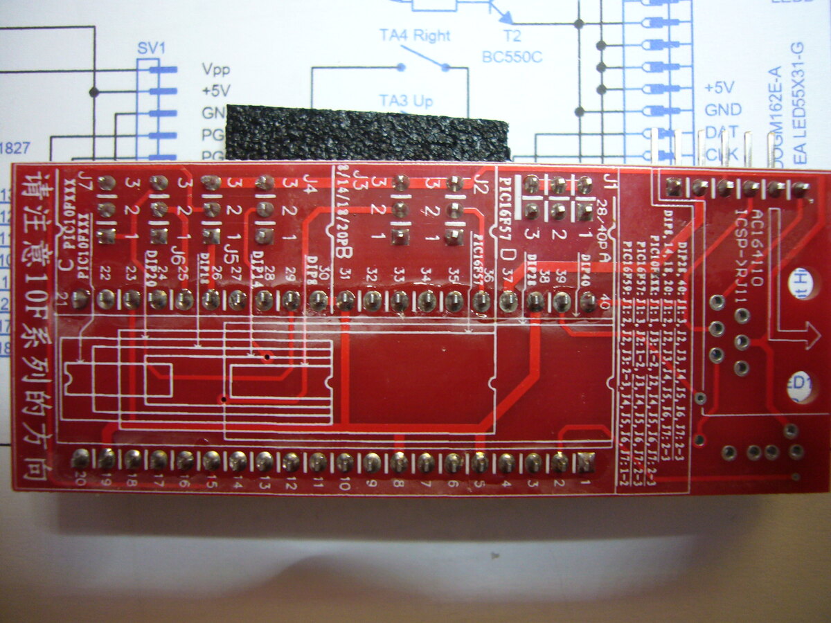
Rote Leiterplatte mit Schaltplan im Hintergrund
SV1 Vpp +5V GN PG PG TA4 Right T2 BC550C TA3 Up J7 3 2 1 J6 25 D210 22 1 J5 27 D214 29 1 J4 31 D218 32 1 J3 33 1 J2 34 1 J1 37 PIC16F57 D216 40 1 39 38 3 2 1 28-pin PIC16F57 D174 bis D177 110 ICSP J11 1 2 3 4 5 6 7 8 9 10 11 12 13 14 15 16 17 18 19 20 请注意10系列的方向
in „PIC Programmieren“ · Mikrocontroller und Digitale Elektronik · · Platinenfotos
-
 Bild
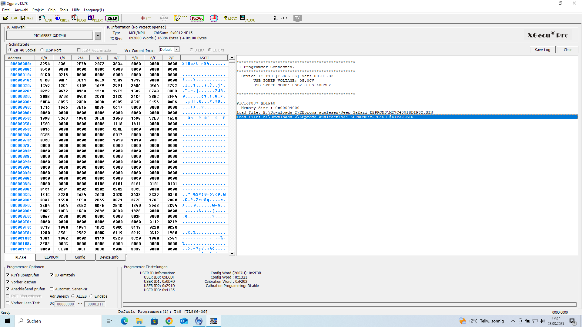
Software zur Programmierung eines PIC-Mikrocontrollers
Xgecu Pro PIC16F857 @DIP40 MCU: PIC16F857 ChNum: 0x0012 Size: 1024 Bytes Programmer: Connected Device: 1 USB SPEED MODE: USB2.0 Load File: E:\Downloads\2\Programm auslesen\E\PIC857\M27C4001DIP92.BIN
in „EEPROM auslesen“ · Mikrocontroller und Digitale Elektronik · · Screenshots
-
Datei
Can.c
unsigned EID16:1; unsigned EID17:1; unsigned :1; unsigned EXIDE:1; unsigned :1; unsigned SID0:1; unsigned SID1:1; unsigned SID2:1; } Bits; } TXBSIDL; union { unsigned char Byte; } TXBEIDH; union { unsigned char Byte
in „PIC18F: Probleme mit CAN“ · Mikrocontroller und Digitale Elektronik ·
-
Datei
PIC-Steuerung.asm
movwf timeshift2 loop3 decfsz timeshift2,f ; decrement middle loop goto loop2 ; middle loop =! 0 return ; return to loop4 loop2 movlw b'10000000' movwf timeshift1 ; load timeshift low loop1 decfsz timeshift1,f ; decrement inner loop goto loop1
in „I2C lesen schlägt fehl. CLK und SDA weiterhin auf low“ · Mikrocontroller und Digitale Elektronik ·
-
Datei
lmx2306.c
Bytedirektiven //************************************************************************** #byte PORTA = 0xF80 #byte PORTB = 0xF81 #byte PORTC = 0xF82 signed init_a=0x14 , init_b=0x94, init_c=0x54; int32 data1=0x83244; int32 data2=0b110101010100111101001000; //data2=0x74F48 int32 frequenz=104900, f_buffer;
in „RDS-Decoder Signal zu schwach?“ · Mikrocontroller und Digitale Elektronik ·
-
Datei
zeitausloeser.bas
Case Intervall Case Is >= 600 : Pic_count = 30 'Die Variable Pic_count wird hier zweckentfremdet! Case Is >= 60 : Pic_count = 10 'weil kein Platz mehr im RAM war... Case Else : Pic_count = 1 End Select Enc = Encoder(pind.0 , Pind.1 ,
in „Zeitauslöser für Casio EX F1 mit attiny2313“ · Projekte & Code ·
-
Datei
led_fade.asm
********************* ; This file is a basic code template for assembly code generation * ; on the PIC16F628A. This file contains the basic code * ; building blocks to build upon. * ; * ; Refer to the MPASM User's Guide for additional information on * ; features of the assembler (Document DS33014). *
in „LEDs an PIC ausglimmen lassen“ · Mikrocontroller und Digitale Elektronik ·
-
PDF
00954A.pdf
Assume maximum value of V Zand R1. within the voltage specification for PIC ® microcontrollers. V RMS = 110 VAC V Z = 5.1V OBSERVATIONS f = 59.5 Hz C = C1 = 0.47 µF x 0.8 = 0.38 µF Figure 2 shows an oscilloscope plot ofOUT at power-
-
PDF
00954A.pdf
Assume maximum value of V Zand R1. within the voltage specification for PIC ® microcontrollers. V RMS = 110 VAC V Z = 5.1V OBSERVATIONS f = 59.5 Hz C = C1 = 0.47 µF x 0.8 = 0.38 µF Figure 2 shows an oscilloscope plot ofOUT at power-
in „Kondensatornetzteil: Frage.“ · Mikrocontroller und Digitale Elektronik ·
-
PDF
transformerless_AC_DC.pdf
Assume maximum value of V Zand R1. within the voltage specification for PIC ® microcontrollers. V RMS = 110 VAC V Z = 5.1V OBSERVATIONS f = 59.5 Hz C = C1 = 0.47 µF x 0.8 = 0.38 µF Figure 2 shows an oscilloscope plot ofOUT at power-
in „230V AC auf 5V DC Bauteile“ · Mikrocontroller und Digitale Elektronik ·
-
Datei
lamps_01.asm
SOFTWARE * ;************************************************************************** ;* Microchip PIC(tm) Programmer & experiment board * ;* DEMO2 program for testing K8048 with PIC16F627(A)! * ;* Generate 4 LED light effects, you can select these with SW1..4 * ;*************************************
in „Pic Lernen aber wie??“ · Mikrocontroller und Digitale Elektronik ·
-
PDF
resteliste_1.pdf
DIL8 OP AMP DUAL MOS IP/BIPOLAR OPAMP 8,00 € ICL7660SCPA 20 DIL8 Ladungspumpenkonverter 10,00 € K6F8016U6D-XF55 20 SMD SAMSUNG 512K x16 bit Super Low Power and Low Voltage Full CMOS Static RAM 20,00 € MAX4066 10 SO16 MAXIM Analog Multiplexer 8,00 € MAX699 25 DIL8 MAXIM Power-On Reset IC IC 5,00 € MAX706
in „Aufräumen und Reste“ · Markt ·
-
Datei
Maxim-Dallas-Liste.txt
docs/7048.pdf us.st.com/stonline/books/pdf/docs/1773.pdf nach cytherm suchen MAX1298 Thermometer with PIC16F84 and LED driver MAX7221 MAX1400 MAX3100 ?? MAX351S 4 Analogschalter für neue DSP-Platine MAX6959 Charlyplexer MAX7221 LED driver for Thermometer with PIC16F84 and MAX1298 DS75 = LM75 kompat DS1775
in „Temperatursteuerung“ · Markt ·
-
Datei
main.c
#include <xc.h> #include <pic16f872.h> //config #pragma config CP = OFF #pragma config WRT = OFF #pragma config CPD = OFF #pragma config LVP = OFF #pragma config BOREN = OFF #pragma config PWRTE = OFF #pragma config WDTE = OFF #
in „Pollin PMT-Modul“ · Mikrocontroller und Digitale Elektronik ·
-
PDF
50002370A.pdf
1 µF low ESR ceramic capacitor. 11 9 P04 DO Status Indicator 2 (STATUS_IND_2). See Section 1.5 “Status Indication I/O Pins”. 12 10 P15 DO Status Indicator 1 (STATUS_IND_1). See Section 1.5 “Status Indication
in „[V] 2St. Microchip Bluetooth4.0 Module RN4677“ · Markt ·
-
Datei
Konsolenlogfile1.txt
driver understands Ada... no checking how to compare bootstrapped objects... cmp --ignore-initial=16 $$f1 $$f2 checking for objdir... .libs checking whether to use debuginfod... auto checking for debuginfod_begin in -ldebuginfod... no checking whether debuginfod_begin is declared... no configure: WARNING
in „Toochain bauen avr-gcc-x.x mit binutils-2.34 funktioniert nicht“ · Mikrocontroller und Digitale Elektronik ·
-
Datei
i2c.c
#include <pic.h> #include "delay.h" #include "i2c.h" /* I2C functions for HI-TECH PIC C - master mode only TIMING - see Philips document: THE I2C-BUS SPECIFICATION Send stop condition - data low-high while clock
in „Serielle Verbindung 2-er PICs“ · Mikrocontroller und Digitale Elektronik ·
-
PDF
Forum.PDF
cPU10adc01 1 2 14 CH4+ 2 IPano4g cPU10adc01 CH4- 0-10VAnalog 6 5 IP10adc06 VDD VSS PIU10adc05 +5 MCP3428-E/ST GND C C +5 +5 1 PC1 CO2_ cadc PIc CO 1_ cadc PC 100nF1206 2 PIc CAP10uF6.3V1206(3216) GND GND D Title
in „Raspberry Pi Compute Module 3 (Carrier Board)“ · Mikrocontroller und Digitale Elektronik ·
-
PDF
PWM_Motor.PDF
E R13 U2 PIC0 PC31 PICO R PR1 PI3 PIU21A VCCPI20 100nF/50V PQ 2 3 STTH512FP +5VDC _ 1k6 GND_PWR Q3 TP9 PP1 PL2 PI0 PI VCC PI108 L PI20 PI31 STN1NK80Z 2 x 1mH/2.5A Phase PER PT i i FILTERPItr 73.5us N TP10 PP1 PIU23
in „PWM HVDC Motor Ansteuerung“ · Analoge Elektronik und Schaltungstechnik ·
-
Datei
CAN.htm
" height="16" width="35%"><font face="Verdana" size="2"><strong>Tq (Time Quanta)</strong></font></td> <td bgcolor="#C0C0C0" height="16" width="65%"><font face="Verdana" size="2">1,000 µs</font></td> </tr> <tr> <td
in „MCP2515 CNF 1-3 Berechnung / Einstellen“ · Mikrocontroller und Digitale Elektronik ·
-
Datei
led_fade_.asm
, 64, 32, 16, 8, 4, 2, 1 dt 1, 2, 4, 8, 16, 32, 64, 128 , 128, 64, 32, 16, 8, 4, 2, 1 dt 1, 2, 4, 8, 16, 32, 64, 128 , 128, 64, 32, 16, 8, 4, 2, 1 dt 1, 2, 4, 8, 16, 32, 64, 128 , 128, 64, 32, 16, 8, 4, 2, 1 dt 1
in „LEDs an PIC ausglimmen lassen“ · Mikrocontroller und Digitale Elektronik ·
-
PDF
AVR-DD-Product-Brief-DS40002215A-1.pdf
AVR16DD14 AVR16DD20 AVR16DD28 AVR16DD32 Feature AVR32DD14 AVR32DD20 AVR32DD28 AVR32DD32 AVR64DD14 AVR64DD20 AVR64DD28 AVR64DD32 Pins 14 20 28 32 PORT PA[1:0], PC[3:1],PA[7:0], PC[3:1]PA[7:0], PC[3:0]PA[7:0
in „AVR-DD im Anrollen“ · Mikrocontroller und Digitale Elektronik ·
-
PDF
EjN-ST-A10_LIUST-5X_CustomerDisplay.pdf
8x16) ESC\?LW2 1B 5C 3F 4C 57 32 ;Pn;Pc;Pd…Pd 3B Pn 3B Pc 3B Pd…Pd Full size(16x16) ESC\?LW3 1B 5C 3F 4C 57 33 ;Pn;Pc;Pd…Pd 3B Pn 3B Pc 3B Pd…Pd Half size(12x24) ESC\?LW4 1B 5C 3F 4C 57 34 - - - * ;Pn;Pc;
in „Hat schon jemand was mit dem FUJITSU VF60 Display gemacht?“ · Mikrocontroller und Digitale Elektronik ·
-
Datei
ZaehlerZahlenUhrvergleich.asm
;Der 16F690 bekommt über RA0 und RA3 den Starttakt und Arbeitstakt von einem ;Pic 16F690 ( Taktgeber ). Dieser schaltet an einer LED Matrix 15X5 die Anoden. ;Das unten aufgeführte Programm schaltet in abhängugkeit
in „PIC 16F690 , ich komm da jetzt nicht weiter“ · Mikrocontroller und Digitale Elektronik ·
-
Datei
cam.c
0x081 ); CamSetReg( 0x240b,0 ); CamSetReg( 0x240c,0x019 ); CamSetReg( 0x240d,0 ); CamSetReg( 0x240e,0x16 ); CamSetReg( 0x240f,0 ); CamSetReg( 0x2410,0x25 ); CamSetReg( 0x2411,1 ); CamSetReg( 0x2412,0x4A ); CamSetReg( 0x2413,1 ); CamSetReg( 0x2414,0x070 ); CamSetReg( 0x2415,0 ); CamSetReg( 0x2416,0x80 );
in „pollin kamera au-85“ · Mikrocontroller und Digitale Elektronik ·
-
Datei
demo1.asm
SAMPLE SOFTWARE * ;************************************************************************** ;* DEMO1: Simple Running light for testing LD1...LD5 * ;* DEMO1: Program for testing K8048/VM111 with PIC16F627! * ;************************************************************************** ;* (C) VELLEMAN Components
in „PIC16F627a Anfänger“ · Mikrocontroller und Digitale Elektronik ·
-
Datei
test.asm
SAMPLE SOFTWARE * ;************************************************************************** ;* DEMO1: Simple Running light for testing LD1...LD5 * ;* DEMO1: Program for testing K8048/VM111 with PIC16F627! * ;************************************************************************** ;* (C) VELLEMAN Components
in „8x8Matrix PIC 16F627a“ · Mikrocontroller und Digitale Elektronik ·
-
PDF
semicon.pdf
PIC16F877 04/PT LQFP44 354 IC Microchip PIC16F877 20/L LQFP44 20 IC Atmel AT90S4414 4AI LQFP44 640 IC NEC uPD70F3007GC 25 TQFP100 360 IC Xilinx XCS30XL 5TQ 144C TQFP 144 50 IC Sharp LH28F160BJE TTL90 Flash
in „4" TFT für 7,97€“ · Markt ·
-
Datei
main.c
pic_init(void); unsigned char uart_rec(void); void main(void) { unsigned char data; pic_init(); while(1) { data = uart_rec(); if(data == 'a') { LATC = 0x01; } else if(data == 'b') { LATC = 0x00; } } } void pic_init(void) { OSCCON = 0b01110000; //16 Mhz --> Internal OSCI --> 9600 Baud Rate TRISC = 0x00; TRISBbits.TRISB5 = 1; //RB5 (RX --> INPUT) TRISBbits.TRISB7 = 0; //RB7 (TX --> OUTPUT) ANSELHbits.ANS11=
in „PIC18 connected to RN42“ · Mikrocontroller und Digitale Elektronik ·
-
PDF
BM83_Embedded_Mode_Reference_Circuit_PCB.pdf
CO19 C20 C21 P1uF C23 1k P0 P 0.1uF P 10uF P11uF 16V PI1uF PR0402 SMBJ10CA-TR16V 25V 16V 0402 16V PD1% 0402 0603 0402 0402 D12 PD Red GND CL2 GND GND P1 PI 4.7uH NOTE: 1). Using 3V3 LDO supply for BM83's BAT_IN, ensure
in „BM83SM1-00TA Blootoh Audio“ · Mikrocontroller und Digitale Elektronik ·
-
PDF
1-Walther__Article.pdf
cents. U2 is a Microchip TC4427A FET driver in DIP package. I chose this unit to protect both the PIC and the FET’s. It can be soldered into the board. However, placing it in a socket is an option. The Mouser part is 579-TC427CPA. Cost is $1.36. U3 is a Microchip PIC 12F683 microcontroller, installed in a socket to allow possible reprogramming. The PIC must be programmed before it is installed. Mouser part is 579- PIC12F683-I/P. It costs $1.41. L1 is a 330uh coil rated for 0.38 amps. Mouser part is 580-22R334. It costs 60 cents. Q1 and Q2 are FQD12N20L
-
Datei
EmulatorPIC16F84.py
import sys from enum import Enum class PIC16F84Emulator: def __init__(self): # Speicher self.flash = [0] * 1024 # Programmspeicher (1024 Worte) self.ram = [0] * 68 # Daten-RAM (0x0C bis 0x4F) self.eeprom = [0] * 64 # EEPROM-Daten # Register
-
Datei
PORTB_TEST.asm
********************* ; This file is a basic code template for assembly code generation * ; on the PIC16F871. This file contains the basic code * ; building blocks to build upon. * ; * ; Refer to the MPASM User's Guide for additional information on * ; features of the assembler (Document DS33014). *
in „Keine Output am Pic“ · Mikrocontroller und Digitale Elektronik ·
-
Datei
main.c
pic_init(void); void uart_rec(); void IntVectLow (void); void abc (void); void main(void) { pic_init(); IntVectLow(); } void pic_init(void) { OSCCON = 0b01110000; //16 Mhz --> Internal OSCI --> 9600 Baud
in „PIC18 connected to RN42“ · Mikrocontroller und Digitale Elektronik ·
-
Datei
ISR_Timer_Beispiel.ASM
wie möglich gehalten sein. ; ; Gute Infos zum Interrupt etc. bei: ; [http://www.sprut.de/electronic/pic/int/int.htm] ; #define TICK_ON bsf FlagReg,0 ; #define TICK_OFF bcf FlagReg,1 ; #define STOPUHR_ON bsf FlagReg,1 ; #define STOPUHR_OFF bcf FlagReg,1 ; vgl zu "#define": ; [http://www.sprut.de/electronic
in „Achtung: Anfänger! PIC16F628 Fehlermeldung beim Assemblieren“ · Mikrocontroller und Digitale Elektronik ·
-
PDF
200959141322092079_SD600Apdf.pdf
for SPI Slave PIC18F4620 28 DIP CPP1 (pin13)-->SCK(PIN14) and RB6 (PIN27) and SD600 CLK SDO(PIN16 to SD600 DIN RC0(PIN11) --> LED indicator delay_ms detect RB6 for time delays */ // PWM init 340K CCP1CON=0x0c; CCPR1L=16; PR2=32; T2CON=0x04; 10 YDSCO 科技创新生活 PORTCbits.RC2=1;//LED //SPI init TRISC=0x08; ADCON1=0x0f; TRISA=0x20;//RA%/SS as digital input PORTCbits.RC0=1; OpenSPI(SLV_SSON,MODE_10,SMPMID);//SPI init while(
in „"intelligent" LED Leiste“ · Mikrocontroller und Digitale Elektronik ·
-
Datei
code.c
// Device: PIC16F627A #include <pic.h> void warte (); void initLCD (); void updateLCD (); void setCursor (uchar DISPLAY_ON, uchar CURSOR_ON, uchar BLINKING); void setCursorHome (); void setEntryMode (uchar MOVE_RIGHT
in „Banks adressieren unter C“ · Mikrocontroller und Digitale Elektronik ·
-
PDF
AD5415.pdf
2C1 PHASE COMPENSATION (1pF TO 2pF) MAY BE REQUIRED, 4 IF A1 IS A HIGH SPEED AMPLIFIER. 0 Figure34.BipolarOperation Rev. 0 | Page 16 of 28 AD5415 SINGLE-SUPPLY APPLICATIONS VOLTAGE SWITCHING MODE OF OPERATION
in „D/A mit Stromausgang“ · Mikrocontroller und Digitale Elektronik ·
-
PDF
io-controller-hub-9-datasheet.pdf
F1/F2)..................................................632 16.1.3 PCICMD—PCI Command Register (USB—D29:F0/F1/F2/F3, D26:F0/F1/F2)...633 16.1.4 PCISTS—PCI Status Register (USB—D29:F0/F1/F2/F3, D26:F0/F1
in „FLASH Memory Chip im Lenovo X200 von 8 MB auf 16 MB vergroessern“ · PC Hard- und Software ·
-
PDF
MCP4261-DigitalPot-2Fach-50kDATASHEET.pdf
IHH Pull-down Current V DD= 5.5V, CS = 12.5V — 170 — µA CS pin, DD= 5.5V, CS = 3V CS Pull-up / RCS — 16 — kΩ V DD= 5.5V, CS = 3V Pull-down Resistance Input Leakage IIL -1 — 1 µA V IN= VDD and VIN= VSS Current Pin Capacitance CIN, OUT — 10 — pF fC= 20 MHz Note 1: Resistance is defined as the resistance
in „Step Down Regler zu heiss & Fragen zur Umsetzbarkeit einer Schaltung“ · Analoge Elektronik und Schaltungstechnik ·
-
PDF
sammelbestellung.pdf
sofort SMD/SMT 1206 0.1uF 25volts X7R 10% RoHS: RoHS: Konform durch Ausnahmegenehmigung 4,05 € 8,10 € Mouser-Nr.: 877-FM16W08-SG 2 Herst.- Nr.: FM16W08-SG Verfügbarkeit 2 Versand sofort Hersteller: Cypress Semiconductor Beschr
-
Datei
TFT3.2.c
---------------------- void draw_line(int x0, int y0, int x1, int y1, char VH, char VL) { int16_t dx = abs(x1-x0); int16_t sx = x0 < x1 ? 1 : -1; int16_t dy = -abs(y1-y0); int16_t sy = y0 < y1 ? 1 : -1; int16_t err = dx + dy; int16_t e2; for (;;) { pixel(x0, y0
-
Datei
clock_porta_forumpost.c
#define __16f627 #include "pic/pic16f627.h" typedef unsigned int word; word at 0x2007 __CONFIG = _BODEN_ON & _CP_OFF & _DATA_CP_OFF & _PWRTE_ON & _WDT_OFF & _LVP_OFF & _MCLRE_OFF & _INTRC_OSC_NOCLKOUT; // 0x3f61 & _MCLRE_ON & _INTRC_OSC_CLKOUT; void main(void) { int i, j; TRISA = 0; PORTA = 0x3f; while (1) { for (i = 0; i < 200; i++) { for (j = 0; j < 255; j++) { } } PORTA ^= 0x3f; } }
in „ausgänge PORTA vom pic wollen nicht so recht in C“ · Mikrocontroller und Digitale Elektronik ·
-
Datei
read_cf_as.asm
list p=16f877 include p16f877.inc count1 equ 0x20 ;Zählervariblen count2 equ 0x21 count3 equ 0x22 lo_byte equ 0x30 ;Ergebniszelle ;Portbelegung: ;PortA bit 1: REG ; 2: WAIT ; 3: RESET ; 4: READY ; 5: WE ; 6: OE
in „CompactFlasch-Karte im Memory Mode ansteuern“ · Mikrocontroller und Digitale Elektronik ·
-
Datei
HP_Test.c
0x61 SchreibeZuLCD('l', ZEICHEN);//0x6C SchreibeZuLCD('l', ZEICHEN); SchreibeZuLCD('o', ZEICHEN);//0x6F pause(1000); SchreibeZuLCD(0b.0000.0001, STEUERBEFEHL);// Display löschen, Cursor Home wait(1); // diese Zeile hat keine Bedeutung }//while(1) } //====================================================
in „PIC16F676 LCD_Init“ · Mikrocontroller und Digitale Elektronik ·
-
PDF
MCP4151.pdf
Current VDD = 5.5V, CS= 12.5V — 170 — µA CS pin, V = 5.5V, V = 3V DD CS CS Pull-up / R CS — 16 — kΩ VDD = 5.5V, CS= 3V Pull-down Resistance Input Leakage IIL -1 — 1 µA VIN= VDD and VIN= VSS Current Pin Capacitance CIN, OUT — 10 — pF C = 20 MHz RAM (Wiper) Value Value Range N 0h — 1FFh hex 8-bit
in „Frage zum MCP4151 SPI Digital Poti?“ · Mikrocontroller und Digitale Elektronik ·
-
PDF
A200_MCP1407-EP_MIC.pdf
warranted range. Note: Unless otherwise indicated, T = +A5°C with 4.5V <= V DD <= 18V. 120 80 10,000 pF 10,000 pF 70 8,200 pF 100 8,200 pF 4,700 pF 4,700 pF ) 2,500 pF )60 1,000 pF n 80 n 2,500 pF 6,800 pF e 1,000 pF (50 i 60 6,800 pF m40 T T s 40 l30 R F 20 20 10 100 pF 100 pF 0 0 4 6 8 10 12 14 16 18
in „Treiber für IRF1404 ?“ · Mikrocontroller und Digitale Elektronik ·
-
PDF
20002019c.pdf
s RISE s t IN ( 25 (75 D1 e y i 20 tFALL l T D65 a 15 n D2 F t 55 n 10 g a a i 5 r45 R P 0 35 -40 -25 -10 5 20 35 50 65 80 95 110 125 4 6 8 10 12 14 16 18 Temperature ( C) Supply Voltage (V) FIGURE 2-3: Rise and Fall Times vs
in „Pulsschweisgerät mit Auto Batt Schaltungs Verbesserung“ · Analoge Elektronik und Schaltungstechnik ·