-
PDF
lcd_manual.pdf
External Microprocessor . . . . . . . . . 21 Contrast Control Voltage . . . . . . . . . . . . . . . . 24 Sample Instruction Procedures . . . . . . . . . . . . . 24 HANDLING INSTRUCTIONS . . . . . . . . . . . . . . . . 28 OPERATING RESTRICTIONS . . . . . . . . . . . . . . . 29 Display Unit User’s Manual
in „Fehler bei 4Bit LCD Init?“ · Mikrocontroller und Digitale Elektronik ·
-
PDF
lcd-spec.pdf
External Microprocessor . . . . . . . . . 21 Contrast Control Voltage . . . . . . . . . . . . . . . . 24 Sample Instruction Procedures . . . . . . . . . . . . . 24 HANDLING INSTRUCTIONS . . . . . . . . . . . . . . . . 28 OPERATING RESTRICTIONS . . . . . . . . . . . . . . . 29 Display Unit User’s Manual
in „LCD Tutorial“ · Mikrocontroller und Digitale Elektronik ·
-
PDF
lcd_manual.pdf
External Microprocessor . . . . . . . . . 21 Contrast Control Voltage . . . . . . . . . . . . . . . . 24 Sample Instruction Procedures . . . . . . . . . . . . . 24 HANDLING INSTRUCTIONS . . . . . . . . . . . . . . . . 28 OPERATING RESTRICTIONS . . . . . . . . . . . . . . . 29 Display Unit User’s Manual
in „LCD will nicht“ · Mikrocontroller und Digitale Elektronik ·
-
PDF
SW017_ISO_tag_DS.pdf
84 101102 128 Header Identification code CRC Extension 11 bits 16 + 2 bits24 + 3 bits 64 + 8 bits National code Country Reser 64 send first 27 26 171615 2 1 64 bits pattern identification code ISO 11784 Figure 2 : Memory Map § Data encoder The data is coded according to the FDX-B
in „Kontaklose Chipkarten????“ · Mikrocontroller und Digitale Elektronik ·
-
PDF
xr20m1170.pdf
2 I ORDERING INFORMATION PART N UMBER PACKAGE OPERATING TEMPERATURE RANGE D EVICESTATUS XR20M1170IL24-F 24-pin QFN -40°C to +85°C Active XR20M1170IL24TR-F 24-pin QFN -40°C to +85°C Active XR20M1170IL16-F 16-pin QFN -40°C to +85°C Active XR20M1170IL16TR-F 16-pin QFN -40°C to +85°C Active XR20M1170IG24
in „UART XR20M1170: Register LCR läßt sich nicht ändern.“ · Mikrocontroller und Digitale Elektronik ·
-
PDF
HP3610_Service_Manual.pdf
fntft w uy ,Af c sUxTHf9Of2fTHf@9OD zlgtysgyfzmaa gyf28 ttfyesgfTHHfmSfabtfsg,f-fbSfc sUfyl %47-HSPf( 2Bf-Mf(f( f21*f(fk fB2TfSfw 21=f4fSf %47--SPf( 2Bf4Mf(f( 21==fTHf(fk2fBfHA*MfSfw21Bf-AMfSf c sUxTHf9Of2fTHf@9OD %47-TSPf( 2 ffBf-THf(f(21Bf7Hf(fk 2BfHATMfSfw 21=▯HAMfSf :G*UGED:TEGdEDPMGOd Hfylf=H▯zfolafomwwfasy
in „Fragen zu Labornetzteilbau (Nachbau Funkschau 1973)“ · Analoge Elektronik und Schaltungstechnik ·
-
Datei
debug_okay.asm
SPE); // SPI Enable 438: 8c b5 in r24, 0x2c ; 44 43a: 8f 7b andi r24, 0xBF ; 191 43c: 8c bd out 0x2c, r24 ; 44 43e: 08 95 ret 00000440 <spi_transfer_byte>: // Writes one byte to target device and returns the received one uint8_t spi_transfer_byte
in „Fehler bei einfacher Integer-Division?“ · Mikrocontroller und Digitale Elektronik ·
-
Datei
ADC-CONV.ASM
def a1 =r17 .def a2 =r18 .def a3 =r19 .def a4 =r20 .def a5 =r21 .def b0 =r22 .def b1 =r23 ;.def b2 =r24 ;.def b3 =r25 ;.def b4 =r26 ;.def b5 =r27 .def e0 =r24 .def e1 =r25 .def e2 =r26 .def e3 =r27 .def e4 =r28 .def e5 =r29 .def e6 =r30 .def e7 =r31 ldi b3,0x03 ldi b2,0xff ldi b1,0x20 mul b1,b2 ;alternatively
in „1023 auf 100% umformen“ · Mikrocontroller und Digitale Elektronik ·
-
PDF
DEM20485SBH-PW-N.pdf
address in address address counter Whether during internal Read busy operation or not can be flag& L H BF AC6 AC5 AC4 AC3 AC2 AC1 AC0 0us known by reading BF.The address contents of address counter can also be read. Write data into internal Write data RAM H L D7 D6 D5 D4 D3 D2 D1 D0 37us to RAM (DDRAM/CGRAM
in „LCD DEM20485 in gerade Zeile springen (c't-Bot)“ · Mikrocontroller und Digitale Elektronik ·
-
Datei
channel_scan_raw.txt
1B 0 15 73104619 72819005 801100624049C2000005370000000099F82466BF 66BF 1 C33 40 029337524 00 1946107301 005A 0B 1 15 73104619 72819005 FFB04BC8 4BC8 1 C33 40 029440380 00 1946107301 00DA 1B 1 15 73104619 72819005 801100624049C50000053700000000A9DE354C29 4C29 1 C11
in „Wechselrichter Hoymiles HM-xxxx 2,4 GhZ Nordic Protokoll?“ · Mikrocontroller und Digitale Elektronik ·
-
PDF
PIC_32_MX_110_F_016_-_I-SO__11-2-3___SO_28_.pdf
1) Memory Map (1) 0xFFFFFFFF 0xFFFFFFFF 0xBFC00C00 Reserved 0xBFC00BFF Device Configuration 0xBFC00BF0 Registers 0xBFC00BEF Boot Flash 0xBFC00000 0xBF900000 Reserved 0xBF8FFFFF SFRs 1 Reserved G 0xBF800000 S K Reserved 0xBD004000 0xBD003FFF (2) Program Flash 0xBD000000 0xA0001000 Reserved 0xA0000FFF
in „pic32 flash und i/o speed“ · Mikrocontroller und Digitale Elektronik ·
-
PDF
PIC_32M_X_220_F_032_B-50I-SP_____DIP_28_.pdf
1) Memory Map (1) 0xFFFFFFFF 0xFFFFFFFF 0xBFC00C00 Reserved 0xBFC00BFF Device Configuration 0xBFC00BF0 Registers 0xBFC00BEF Boot Flash 0xBFC00000 0xBF900000 Reserved 0xBF8FFFFF SFRs 1 Reserved G 0xBF800000 S K Reserved 0xBD004000 0xBD003FFF (2) Program Flash 0xBD000000 0xA0001000 Reserved 0xA0000FFF
in „PIC32MX flash access time“ · Mikrocontroller und Digitale Elektronik ·
-
PDF
ss.pdf
Toff= NK 2 0 A 2 V + V Rx AB 0 TAB = NK 2V AB+V 0 3 V CD+ V 0 T = NK (V +V ) B CD 2 CD 0 Rref 4 V BF+ V0 T = NK (V +V ) BF 2 BF 0 F 5 V EA2 + V 0 T = NK (V / 32+V ) EA 2 EA 0 Figure 15. Connections of the sensors to the UTI Table 24. Signals during the various phases of mode Brg2 The voltage across
in „Temperaturmessung mit PT100 und UTI03“ · Mikrocontroller und Digitale Elektronik ·
-
PDF
DSUTI.pdf
Toff= NK 2 0 A 2 V + V Rx AB 0 TAB = NK 2V AB+V 0 3 V CD+ V 0 T = NK (V +V ) B CD 2 CD 0 Rref 4 V BF+ V0 T = NK (V +V ) BF 2 BF 0 F 5 V EA2 + V 0 T = NK (V / 32+V ) EA 2 EA 0 Figure 15. Connections of the sensors to the UTI Table 24. Signals during the various phases of mode Brg2 The voltage across
in „PT1000 mit UTI messen Berechnung der Auflösung bzw. max. Tempbereich“ · Mikrocontroller und Digitale Elektronik ·
-
PDF
obC16x.pdf
im Assemblercode vermieden werden. Beispiel: PROCEDURE* Fstep(VAR step:INTEGER; cur:INTEGER); VAR bf:INTEGER; BEGIN bf := step * 2; (* bf = R13, mal 2 wg. Word *) VERBATIM jmp Fstepnext SHsteptable DW 224, 255, 7, 127, 96, 125, 5, 253 Fstepnext mov R12, #SHsteptable add R12, R13 mov R13, [R11] ; Wert nach bf laden END_VERBATIM IF cur = 2 THEN (* mittlerer Strom *) bf := bf ANDB %10111110; ELSIF cur = 1 THEN (* niedriger Strom *) bf := bf ANDB %11011011; ELSIF cur = 0 THEN (* Strom aus *) bf := bf ANDB %10011010
in „Ein kleiner Oberoncompiler für die C16x-Familie“ · Projekte & Code ·
-
Datei
kicad-gdb-crash-log.txt
libdatrie1-debuginfo-0.2.4-22.3.x86_64 libdbus-1-3-debuginfo-1.8.22-5.1.x86_64 libexpat1-debuginfo-2.1.0-24.1.x86_64 libffi4-debuginfo-5.3.1+r233831-10.1.x86_64 libfreetype6-debuginfo-2.6.3-5.3.1.x86_64 libgcc_s1-debuginfo-8.2.1+r264010-2.3.x86_64 libgcrypt20-debuginfo-1.6.1-48.1.x86_64 libgdk_pixbuf-2_0-0
in „KiCad 5.0.2 - Absturz beim Footprint-Editor Aufruf“ · Platinen ·
-
PDF
apple_macbook_pro_a1286_mlb_d1_051-9216_13.3_retina_a1425_820-3462_sch.pdf
_L D44 RESET* W (IPU) BPM_0* G58 XDP_BPM_L<0> BI 24 72 402LF P A (IPU) E55 XDP_BPM_L<1> T BPM_1* BI 24 72 27 OUT =MEM_RESET_L AT30 SM_DRAMRST* C J (IPU) BPM_2* E59 XDP_BPM_L<2> BI 24 72 S (IPU) BPM_3* G55 XDP_BPM_L<3> 24 72 72CPU_SM_RCOMP<0> BF44 SM_RCOMP
in „Macbook Schaltpläne“ · Mikrocontroller und Digitale Elektronik ·
-
PDF
RasperryPI_CAN-S.pdf
5V 1 2 2 1 SDA 3 4 4 3 SCL 7 8 8 7 ONEWIRE 9 10 10 9 INT 11 12 12 11 IN_G 13 14 14 13 IN_X 15 16 OUT24V 16 15 17 18 IN_H 18 17 MOSI 19 20 20 19 MISO 21 22 IN_I 22 21 B SCK 23 24 CS0 24 23 B 25 26 IN_J 26 25 27 28 28 27 ENC_A 29 30 30 29 ENC_B 31 32 IN_F 32 31 ENC_PUSH 33 34 34 33 IN_A 37 38 IN_E 38 37
in „MCP2515 CAN-Bus Modul“ · Mikrocontroller und Digitale Elektronik ·
-
PDF
i2c.pdf
further. If you need more informationon SMBus, consult the specification. 47 I C - PICmicro (SSPSTAT) l BF stands for Buffer Full l BF is set when the SSPBUF needs to be read l BF is set and cleared by the PICmicro MCU 2 Getting Startred: I C Master Mode © 2001 The “BF” bit stands for “Buffer Full”. When
in „PIC16F877 über I2C mit zweitem PIC16F877 verbinden- wie Funktioniert das?“ · Mikrocontroller und Digitale Elektronik ·
-
PDF
LTSpice_XVII__Tutorial.pdf
. Symmetrischer Betrieb 204 23.4. Die Gilbert-Cell, als Double Balanced Mixer (DBM) eingesetzt 206 24. Achtzehntes Projekt: Modulation 210 24.1. Prinzip der Amplitudenmodulation (AM) 210 24.2. Amplitude Shift Keying (ASK) 212 24.3. Die Frequenzmodulation (FM) 213 24.3.1. Erzeugung eines FM-Signals mit der Spannungsquelle „voltage213 24.3.2. FSK = Frequency Shift Keying 215 24.4. Quadratur-Amplitudenmodulation (QAM) 217 24.4.1. Grundlegende Informationen 217 24.4.2. Erzeugung eines QAM-Signals 218 24.4.3. Filterung des QAM-Signals zur
in „Triac selbsterhaltend triggern“ · Analoge Elektronik und Schaltungstechnik ·
-
PDF
LTSpice_XVII__Tutorial_korr.pdf
. Symmetrischer Betrieb 204 23.4. Die Gilbert-Cell, als Double Balanced Mixer (DBM) eingesetzt 206 24. Achtzehntes Projekt: Modulation 210 24.1. Prinzip der Amplitudenmodulation (AM) 210 24.2. Amplitude Shift Keying (ASK) 212 24.3. Die Frequenzmodulation (FM) 213 24.3.1. Erzeugung eines FM-Signals mit der Spannungsquelle „voltage213 24.3.2. FSK = Frequency Shift Keying 215 24.4. Quadratur-Amplitudenmodulation (QAM) 217 24.4.1. Grundlegende Informationen 217 24.4.2. Erzeugung eines QAM-Signals 218 24.4.3. Filterung des QAM-Signals zur
in „Simulation LT Spice“ · Analoge Elektronik und Schaltungstechnik ·
-
Datei
interrupt_asm.txt
GOTO 1B6 01B8: MOVF 1A,W 01B9: MOVWF 31 01BA: MOVF 31,W 01BB: SUBLW 1B 01BC: BTFSS 03.2 01BD: GOTO 1BF 01BE: GOTO 2BB 01BF: MOVLW C0 01C0: IORWF 0B,F 01C1: CLRF 0F 01C2: CLRF 0E 01C3: CLRF 2C 01C4: CLRF 2B 01C5: MOVLW C8 01C6: ADDWF 33,W 01C7: SUBWF 32,W 01C8: BTFSC 03.0 01C9: GOTO 1D1 01CA: MOVLW A6
in „PIC 16F876 Timer Interrupt“ · Mikrocontroller und Digitale Elektronik ·
-
 Bild
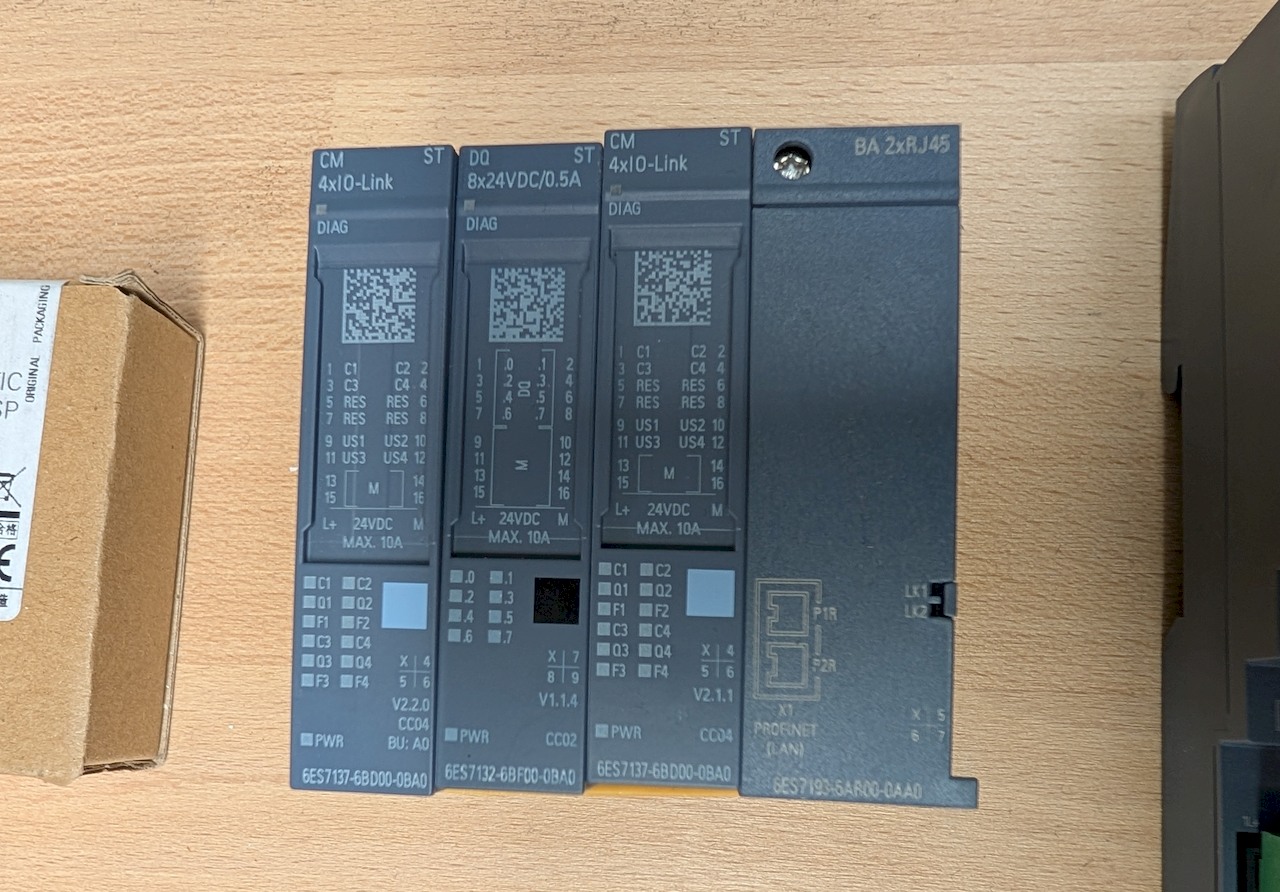
Vier Siemens SIMATIC I/O Module
CM 4xI0-Link, ST, DQ 8x24VDC/0.5A, ST, BA 2xRJ45, DIAG, C1 bis C4, RES, US1 bis US4, M, L+, 24VDC, MAX. 10A, 6ES7137-6BD00-0BA0, 6ES7132-6BF00-0BA0, 6ES7137-6BD00-0BA0, 6ES7193-5AR00-0AA0
in „[V] Siemens ET 200SP F-CPU inkl. diversen Modulen, Base-Units, Profinet-Modul - GESAMTPAKET“ · Markt · · Fotos
-
Datei
G32trust.asm
esp+24h+var_B], 6Eh mov [esp+24h+var_A], 65h mov [esp+24h+var_9], 6Ch mov [esp+24h+var_8], 53h mov [esp+24h+var_7], 65h mov [esp+24h+var_6], 74h mov [esp+24h+var_5], 75h mov [esp+24h+var_4], 70h mov [esp+24h
in „Wer kann mir eine ASM File compelieren“ · Softwareentwicklung ·
-
PDF
Hexdump.pdf
94 05 28 07 BC 0A 50 0C E4 0F 78 12 0C 14 A0 .”.(.¼.P.ä.x... 000007A0 17 34 19 C8 1C 5C 1E F0 21 84 24 18 26 AC 29 40 .4.È.\.ð!„$.&¬)@ 000007B0 2B D4 2E 68 30 FC 33 90 36 24 38 B8 3B 4C 3D E0 +Ô.h0ü3.6$8¸;L=à 000007C0 40 74 43 08 45 9C 48 30 4A C4 4D 58 4F EC 52 80 @tC.EŒH0JÄMXOìR€ 000007D0 55 14 57 A8
in „Suche Simulator für Motorola 68k“ · Mikrocontroller und Digitale Elektronik ·
-
Datei
DATEN.LST
3053 0BEC FE .byte 254 3054 0BED FE .byte 254 3055 0BEE FE .byte 254 3056 0BEF FE .byte 254 3057 0BF0 FE .byte 254 3058 0BF1 FE .byte 254 3059 0BF2 FE .byte 254 3060 0BF3 F6 .byte 246 3061 0BF4 D6 .byte 214 3062 0BF5 D6 .byte 214 3063 0BF6 D6 .byte 214 3064 0BF7 D6 .byte 214 3065 0BF8 D6 .byte 214 3066
in „Daten auf EPROM 27c512LC brennen / ERTEC PGS53 / Adapter ADPL34/35“ · PC Hard- und Software ·
-
PDF
ssd1803a.pdf
Output SSD1803A Rev 2.0 P 17/69 May 2011 Solomon Systech 7 FUNCTIONAL BLOCK DESCRIPTIONS 7.1 Busy Flag (BF) When BF = "High", it indicates that the internal operation is being processed. So during this time the next instruction cannot be accepted. BF can be read, when RS = Low and R/W = High (Read Instruction
in „Probleme mit EADOGM204-4 und ATMEGA32“ · Mikrocontroller und Digitale Elektronik ·
-
PDF
ssd1803a_2_0.pdf
Output SSD1803A Rev 2.0 P 17/69 May 2011 Solomon Systech 7 FUNCTIONAL BLOCK DESCRIPTIONS 7.1 Busy Flag (BF) When BF = "High", it indicates that the internal operation is being processed. So during this time the next instruction cannot be accepted. BF can be read, when RS = Low and R/W = High (Read Instruction
in „Display DOGM-204A/SSD1803A mit I2C - ROM Auswahl“ · Mikrocontroller und Digitale Elektronik ·
-
Datei
00-ff_letztesByte.txt
0xC2 0xA6 0x5B 0xA7 0xDB 0xA8 0x14 0xA9 0x94 0xAA 0x0D 0xAB 0x8D 0xAC 0x26 0xAD 0xA6 0xAE 0x3F 0xAF 0xBF 0xB0 0xB8 0xB1 0x38 0xB2 0xA1 0xB3 0x21 0xB4 0x8A 0xB5 0x0A 0xB6 0x93 0xB7 0x13 0xB8 0xDC 0xB9 0x5C 0xBA 0xC5 0xBB 0x45 0xBC 0xEE 0xBD 0x6E 0xBE 0xF7 0xBF 0x77 0xC0 0xC0 0xC1 0x40 0xC2 0xD9 0xC3 0x59 0xC4 0xF2 0xC5 0x72 0xC6 0xEB 0xC7 0x6B 0xC8 0xA4 0xC9 0x24 0xCA 0xBD 0xCB 0x3D 0xCC 0x96 0xCD 0x16 0xCE 0x8F 0xCF 0x0F 0xD0 0x08 0xD1 0x88 0xD2 0x11 0xD3 0x91 0xD4 0x3A 0xD5 0xBA 0xD6 0x23 0xD7 0xA3 0xD8 0x6C 0xD9 0xEC 0xDA 0x75 0xDB 0xF5 0xDC 0x5E 0xDD 0xDE
-
Datei
asm.txt
------- { 00000088 SBIS 0x03,0 Skip if bit in I/O register set set_io(LED_PORT, LED); 00000089 IN R24,0x02 In from I/O location } 0000008A LDI R24,0x00 Load immediate 0000008B LDI R25,0x00 Load immediate 0000008C RET Subroutine return --- C:\home\tools\hudson\workspace\avr8-gnu-toolchain\src\gcc\gcc\
in „Codingstyle vs Makros“ · Mikrocontroller und Digitale Elektronik ·
-
Datei
DeviceList.txt
24C16B(SOIC8) 24C16B(TSSOP8) 24C32A 24C32A(SOIC8) 24C32A(TSSOP8) 24C32B 24C32B(SOIC8) 24C32B(TSSOP8) 24C64A 24C64A(SOIC8) 24C64A(TSSOP8) 24C64B 24C64B(SOIC8) 24C64B(TSSOP8) 24C128A 24C128A(SOIC8) 24C128A
in „[V] Genius G540 EPROM/Flash/uC Programmer (USB)“ · Markt ·
-
PDF
Doma2.-16.pdf
1 ADD data is sent and received after this 40µs Set setting. Busy Flag / Address Reads Busy flag (BF) indicating internal 0 1 BF AC operation is being performed and reads - Read address counter contents. CG RAM / DD RAM 1 0 Write Data Writes data into DD RAM or CG RAM 40µs Data write CG RAM / DD RAM
in „Suche Daten zum LCD-Display Wintek WD-G1003P“ · Mikrocontroller und Digitale Elektronik ·
-
Datei
DTU.txt
addr:0x0055 shiftbit9 60 71 70 63 01 (13/0/0) 51(63 70 71 60|72 22 84 12)5a 5a 17 82[9c 31]2b 48 58 bf bf d7 9e d9 57 55 - ch:0x03 size:32 time:0 addr:0x0055 shiftbit9 60 71 70 63 01 (13/0/0) 51(63 70 71 60|72 22 84 12)5a 5a 17 82[9c 31]2e 54 af ad 5b 23 41 29 14 54 - ch:0x03 size:32 time:0 addr:0x0055
in „Wechselrichter Hoymiles HM-xxxx 2,4 GhZ Nordic Protokoll?“ · Mikrocontroller und Digitale Elektronik ·
-
Datei
DTU51.txt
addr:0x0055 shiftbit9 60 71 70 63 01 (13/0/0) 51(63 70 71 60|72 22 84 12)5a 5a 17 82[9c 31]2b 48 58 bf bf d7 9e d9 57 55 - ch:0x03 size:32 time:0 addr:0x0055 shiftbit9 60 71 70 63 01 (13/0/0) 51(63 70 71 60|72 22 84 12)5a 5a 17 82[9c 31]2e 54 af ad 5b 23 41 29 14 54 - ch:0x03 size:32 time:0 addr:0x0055
in „Wechselrichter Hoymiles HM-xxxx 2,4 GhZ Nordic Protokoll?“ · Mikrocontroller und Digitale Elektronik ·
-
PDF
2_16.pdf
8410CNLED 7.9 96.0 48.0 15.0 79.0 27.0 2x8 DIN-Geh LPIPE,Snap-in 14 EA E162-BNLW 9.66 122. 44.0 15.0 99.0 24.0 1x16 017-12U LBOX, neg.blau 13 EA W162-BNLED 9.66 122. 44.0 13.6 99.0 24.0 1x16 017-12U LBOX,Kontrast 13 TECHNISCHE DATEN * INTEGRIERTER KONTROLLER HD44780 ODER KOMPATIBEL * EINGANG 4- ODER 8-BIT DATENBUS
in „LCD ansteuerung mit PIC18F2525“ · Mikrocontroller und Digitale Elektronik ·
-
PDF
Datenblatt_PIC12F1822.pdf
. TOSC (TMR2 Prescale Value) 24.3.3 PWM PERIOD The PWM period is specified by the PR2 register of Timer2. The PWM period can be calculated using the EQUATION 24-3: DUTY CYCLE RATIO formula of Equation 24-1. CCPRxL:CCPxCON<5:4> Duty
in „PIC12F1822-PWM Mode“ · Mikrocontroller und Digitale Elektronik ·
-
PDF
Datenblatt_PIC12F1822.pdf
. TOSC (TMR2 Prescale Value) 24.3.3 PWM PERIOD The PWM period is specified by the PR2 register of Timer2. The PWM period can be calculated using the EQUATION 24-3: DUTY CYCLE RATIO formula of Equation 24-1. CCPRxL:CCPxCON<5:4> Duty
in „Interrupt-PIC12F1822“ · Mikrocontroller und Digitale Elektronik ·
-
PDF
12F1822_1823.pdf
. TOSC (TMR2 Prescale Value) 24.3.3 PWM PERIOD The PWM period is specified by the PR2 register of Timer2. The PWM period can be calculated using the EQUATION 24-3: DUTY CYCLE RATIO formula of Equation 24-1. CCPRxL:CCPxCON<5:4> Duty
in „Auflösung PWM-Mode“ · Mikrocontroller und Digitale Elektronik ·
-
PDF
12F1822_1823.pdf
. TOSC (TMR2 Prescale Value) 24.3.3 PWM PERIOD The PWM period is specified by the PR2 register of Timer2. The PWM period can be calculated using the EQUATION 24-3: DUTY CYCLE RATIO formula of Equation 24-1. CCPRxL:CCPxCON<5:4> Duty
in „8Bits und 2Bits in eine Integer-Variable“ · Mikrocontroller und Digitale Elektronik ·
-
PDF
12F1822_1823.pdf
. TOSC (TMR2 Prescale Value) 24.3.3 PWM PERIOD The PWM period is specified by the PR2 register of Timer2. The PWM period can be calculated using the EQUATION 24-3: DUTY CYCLE RATIO formula of Equation 24-1. CCPRxL:CCPxCON<5:4> Duty
in „Timer2 auf 10bit einstellen“ · Mikrocontroller und Digitale Elektronik ·
-
PDF
PIC12FLF1822PIC16FLF1823.pdf
. TOSC (TMR2 Prescale Value) 24.3.3 PWM PERIOD The PWM period is specified by the PR2 register of Timer2. The PWM period can be calculated using the EQUATION 24-3: DUTY CYCLE RATIO formula of Equation 24-1. CCPRxL:CCPxCON<5:4> Duty
in „PIC16lf1823 General purpose I/Os mit Schmitt Trigger ?“ · Mikrocontroller und Digitale Elektronik ·
-
PDF
Marantz_PM7000PM8000_Service.pdf
3 1 2 4 47R 2SA1962 * 3 2 3 6 1 2 1 ( 0009 3 4 3 1 * 3313 6 1 3327 2 3 100R 7271 7275 7283 6 0 p 3 BF423 2SA1837 10R 2SA1941 # p 2 1 p T021 2 7263 2SA1962 * 7255 2SC3423 0 k 4 3 7 0 N 2SC2240 8 8 8 3 1 6273 -B 5 R W 2 1 ( 5 D 5 1 5 1 6 1 * 3 1 3 SPK2 D 6 N 6 N 6 N 7 4 3 BAV21 VB24MBU p 1 1 1 9 8 5268
in „Marantz Verstärker defekt“ · Analoge Elektronik und Schaltungstechnik ·
-
PDF
JLX12864G-378.pdf
0x00,0x00}; uchar code lei1[]={/*-- 文字: 畾 --*/ /*-- 宋体 12; 此字体下对应的点阵为:宽 x 高=16x16 --*/ 0x80,0x80,0x80,0xBF,0xA5,0xA5,0xA5,0x3F,0xA5,0xA5,0xA5,0xBF,0x80,0x80,0x80,0x00, 0x7F,0x24,0x24,0x3F,0x24,0x24,0x7F,0x00,0x7F,0x24,0x24,0x3F,0x24,0x24,0x7F,0x00}; /*写指令到 LCD 模块*/ void transfer_command_lcd(int data1) { lcd_cs1
-
Datei
zeug.c
0xC5,0xE2,0xF9,0xFC, 0xDE,0xDF,0x1F,0xDF,0xDF,0xFF,0x3F,0xDF,0xDF,0xDF,0x3F,0xFF,0x1F,0x5F,0x5F,0x5F, 0xBF,0xFF,0x1F,0xFF,0x7F,0xFF,0x1F,0xFF,0x7F,0x3F,0x5F,0x3F,0x7F,0xFF,0xDF,0xBF, 0x7F,0xBF,0xDF,0xFF,0xFF,0x00,0x00,0x00,0x00,0x00,0x00,0x00,0x01,0x11,0x11,0xF1, 0x11,0x11,0x01,0xE1,0x11,0x11,0x11,0xE1,0x01,0xF1,0x91,0x91,0x91,0x61,0x01,0xF1
in „Benörige Hilfe bei Grafikdisplay LM240120“ · Mikrocontroller und Digitale Elektronik ·
-
Datei
main.c
0xC5,0xE2,0xF9,0xFC, 0xDE,0xDF,0x1F,0xDF,0xDF,0xFF,0x3F,0xDF,0xDF,0xDF,0x3F,0xFF,0x1F,0x5F,0x5F,0x5F, 0xBF,0xFF,0x1F,0xFF,0x7F,0xFF,0x1F,0xFF,0x7F,0x3F,0x5F,0x3F,0x7F,0xFF,0xDF,0xBF, 0x7F,0xBF,0xDF,0xFF,0xFF,0x00,0x00,0x00,0x00,0x00,0x00,0x00,0x01,0x11,0x11,0xF1, 0x11,0x11,0x01,0xE1,0x11,0x11,0x11,0xE1,0x01,0xF1,0x91,0x91,0x91,0x61,0x01,0xF1
in „Benörige Hilfe bei Grafikdisplay LM240120“ · Mikrocontroller und Digitale Elektronik ·
-
PDF
4804.pdf
L4004F61 Z0409DE T1230-700W L4004F71 Z0409DE BTA21C BTB08-400C L4004F71 BTB04-400S BTA225-600B BTB24-600BW L4004F72 Z0409DF BTA225-800B BTB24-800BW L4004F81 Z0410DE BTA22E BTB10-600C L4004F91 Z0410DE BTB19-700B BTB24-700B L4004F91 BTB06-400C C106A X0402BF L4004F92 Z0410DF C106B X0402BF L4004L3 BTA04
in „Ersatztyp für Thyristo TYN408G“ · Analoge Elektronik und Schaltungstechnik ·
-
Datei
fcntl.lst
,lo8(9) 183 0086 A8F3 brlo .L17 184 .stabn 68,0,68,.LM13-open 185 .LM13: 186 0088 82E1 ldi r24,lo8(18) 187 008a 8093 0000 sts errno,r24 188 008e 82E1 ldi r24,lo8(18) 189 0090 90E0 ldi r25,hi8(18) 190 0092 2AC0 rjmp .L8 191 .stabn 68,0,61,.LM14-open 192 .LM14: 193 .L24: 194 0094 8A81 ldd r24,Y+
in „Compiler-Fehler?“ · Mikrocontroller und Digitale Elektronik ·
-
Datei
keylcd.asm
1: I2C write operation, last byte was an address byte. ; ; SSPSTAT bits: S = 1, D_A = 0, R_W = 0, BF = 1 ; ; State 2: I2C write operation, last byte was a data byte. ; ; SSPSTAT bits: S = 1, D_A = 1, R_W = 0, BF = 1 ; ; State 3: I2C read operation, last byte was an address byte. ; ; SSPSTAT bits: S = 1, D_A = 0, R_W = 1, BF = 0 ; ; State 4: I2C read operation, last byte was a data byte. ; ; SSPSTAT bits: S = 1, D_A = 1, R_W = 1, BF = 0 ; ; State 5: Slave I2C logic reset by NACK from master. ; ; SSPSTAT bits: S = 1, D_A
in „Noritake VFD GU140x32F7806 4-Bit Mode, Initialisierung“ · Mikrocontroller und Digitale Elektronik ·
-
 Bild
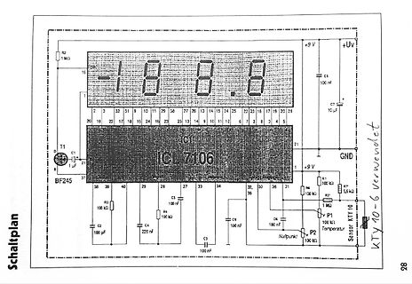
Schaltplan eines Temperaturmessgeräts mit LCD-Anzeige
R2 1 MΩ, 16, 1, 2, 3, 32, 31, 9, 10, 11, 29, 30, 27, 26, 13, 14, 15, 24, 25, 22, 23, 18, 17, 15, 20, 21, 20, 19, 22, 17, 18, 15, 24, 16, 23, 13, 14, 9, 10, 11, 12, 6, 7, 2, 8, 3, 4, 5, 21, 1, +9 V, +Uv, C7 10 µF, GND, R1 100 kΩ, R7 5,6 kΩ, R3 1 MΩ, P1 100 kΩ, Sensor KTY
in „[S] LCD Thermometer mit ICL7106 (Conrad Bausatz)“ · Markt · · Schaltpläne
-
Datei
Castillo33.c
0x8956, 0x9559, 0x5249, 0x0989, 0x555B, 0x5249, 0x8995, 0x2559, 0x9995, 0x6754, 0x5622, 0x2166, 0xBF56, 0x2499, 0x225E, 0xA756, 0x56B5, 0x65A3, 0x6F55, 0x8D52, 0x9596, 0x1E24, 0x7A34, 0x6249, 0x1658, 0xB160, 0x6895, 0xC0B1, 0x596B, 0xF580, 0x05C3, 0x5969, 0x5D05, 0x4555, 0x5551, 0x5905, 0x4589, 0xA151
in „BMP/JPEG/GIF/PNG nach C-Code konvertieren“ · Projekte & Code ·