-
PDF
TLC5940.pdf
LSB MSB LSB MSB th2 su2 su1 h1 wh0 tsu0 t h0 1 96 1 192 193 1 192 193 1 SCLK t twl0 pd0 - DC - - GS1 SID1 SID1 SID1 GS2 SID2 SID2 SOUT MSB MSB MSB MSB-1 LSB MSB MSB MSB-1 twh3 BLANK 1st GS Data Output Cycle 2nd GS Data Output Cycle h4 tsu4 wh1 tsu5 GSCLK 1 4096 1 t pd4 t pd3 Tgsclk twl1 pd1 pd3 OUT0 (current
in „Parallel Nutzung von Stromsenken“ · Analoge Elektronik und Schaltungstechnik ·
-
PDF
TPCDG2FLEX.pdf
than on the inside. It is possible to make a two-layer rigid-flex circuit with a flex circuit on one side and none on the other, with the two sides interconnected by plated through-holes. To assure that the flex areas remain flexible after processing, there are special processing requirements, such as making
-
Datei
sound.c
sound data array. It reads the register address and data from the array and writes it to the "virtual SID registers". 0xF0,0xF1 and 0xFF are no SID registers and interpreted as controll code for the parser. F0+256*F1 gives the value in milliseconds to pause parsing and let the SID playing it's sound. After the pause the next register values are read and written to the SID. At the end of the array ther should be the values 0xFF,0xFF which stop the parser and stop sound generation. syntax: static uint8_t sound[] PROGMEM ={ sidregister,value, sidregister,value, .... 0xF0
in „6502 Emulation auf AVR ?“ · Mikrocontroller und Digitale Elektronik ·
-
PDF
ceramics_trans.pdf
secondary ˔ߴௐϊΠζগ • Low harmonic current noise. electrodes on the piezoelectric ceramic. The primary side is polarized in the thickness direction and the secondary side in the length direction. (Arrow mark shows polarization direction). When a voltage having a resonance frequency (Fr), determined by the ͝ ҙ▯ Cautions length dimension, is input on the primary side, a strong mechani⾣ۦಈ࣌ʹෛՙΛΦʔϓϯʹ͢Δͱഁଛ͢Δ͜ͱ͕͋Γ·͢ɻ oscillation is generated by inverse piezoelectric effect, and a ⾣࠷େఆ֨Λ͑ͯۦಈ͢Δͱಛੑ͕ྼԽ͢Δ߹͕͋Γ·͢ɻ high voltage (Vo) is output from the secondary side, matching
in „Was ist das für ein Bauteil? Resonator? HallSensor?“ · Analoge Elektronik und Schaltungstechnik ·
-
PDF
ksger_t12_v3.pdf
C J1 6 1 PA7 29 C 1 2 PA8 OLED_RST 2 1: Earth/ground 3 PA9 30 OLED_O/C M 31 SDIO 3 2: + (positive side of thermocouple) T PA10 GND SWCLK 4 5: -/heater (negative side of thermocouple and heater supply) S PA11 32 +3V3 33 T SWD PA12 34 A PA13 SDIO _ PA14 37 SWCLK J5 V J2 R5 U3 5 38 1 1 287k 3 PA15 ENC_SW
in „[V] JBC-Äquivalente: JAbe 2245-A UD, drei Spitzen, Knokoo Halter, ksger Lötstation“ · Markt ·
-
PDF
Beamer_Protocol.pdf
B7 as described below are transmitted. Transmission from Transmission from Reception in the Master side the Master side the Master side (With Data) B0 START CODE : 0 x A9 B1 B2 ITEM NUMBER ACK / NAK ITEM NUMBER B3 SET / GET ACK REPLY B4 DATA DUMMY DATA DATA B5 B6 CHECK SUM B7 END CODE : 0 x 9A B0 START
in „Beamer über RS232 bedienen?“ · Mikrocontroller und Digitale Elektronik ·
-
PDF
ToneLabSE_Service_manual.pdf
*471X255004 WAFER JS-1132-04 KLM-2501 1 *471X255007 WAFER JS-1132-07 KLM-2501 1 *472X255004 WAFER SIDE JS-1125R-04 KLM-2485/68/96/7/8/9 1 *472X255006 WAFER SIDE JS-1125R-06 KLM-2485/68/96/7/8/9 1 *472X255007 WAFER SIDE JS-1125R-07 KLM-2485/68/96/7/8/9 1 *472X255008 WAFER SIDE JS-1125R-08 KLM-2485/68/
in „74 HC 595 Defekt feststellen?“ · Mikrocontroller und Digitale Elektronik ·
-
PDF
Microwave_Oven_Inverter_HV_Power_Supply.pdf
sort of flywheel circuit. This circuit from a Toshiba IGBT application note looks similar: 6. The HV side has a full-wave doubler rectifier and is marked 4kV @ 300mA. Unlike the classic microwave oven transformers (where one side of the winding is grounded), this means that the secondary must be well insulated from ground on both sides. A simple reconfiguration of the rectifier (replace the caps with diodes) into a bridge circuit should yield 2kV @ 600mA (depending on the diode ratings) 7. The HV filter capacitors are only 8200 pF
in „Mikrowelle mit weniger als 700 (Nenn-)Watt gesucht__Wieviel gemessene Watt benötigt Eure Mikrowelle?“ · Haus & Smart Home ·
-
PDF
A600_v2.1_Amplifier_Kit_full_assembly_instructions-2.pdf
cable. Wind one turn of coaxial cable through the ferrite core so both ends come out on the same side in equal lengths. With the utility knife, carefully remove the external jacket off both the ends hanging out, remove the shielding and cut most of it, leaving only ~1cm (1/4 inch) on each side. Take
-
PDF
ME8311-Microne.pdf
ME8311 High Precision CC/CV Primary-Side Controller ME8311 General Description Features The ME8311 is a high performance offline PSR ● ±5% Constant Voltage Regulation at universal AC input controller for low power AC/DC charger and adapter
in „Schaltkreis 8311A“ · Analoge Elektronik und Schaltungstechnik ·
-
PDF
CNY70_TEM.pdf
Characteristics (T amb = 25⋅C, unless otherwise specified) ) 300 10 Kodak Neutral Card m ) (White Side) ( A o m 1 d=0.3 a Coupled Device t V CE=5V i 200 e i u r r 0.1 e t o Phototransistor e l 100 o o IR-Diode C T –C 0.01 –t I Pt 0 0.001 0 25 50 75 100 0.1 1 10 100 95 11071 Tamb – Ambient Temperature
in „cny70 funktioniert nicht wie er sollte“ · Mikrocontroller und Digitale Elektronik ·
-
PDF
CNY_VISHAY.pdf
0.3 V ration voltage d = 0.3 mm (figure 1) 1) Measured with the ‘Kodak neutral test card’, white side with 90% diffuse reflectance 2)Measured without reflecting medium Reflecting medium d ~~ (Kodak neutral test card) ~ ~~ ~ Emitter Detector A C C E 95 10808 Figure 1. Test circuit Document Number 83751
in „cny70 funktioniert nicht wie er sollte“ · Mikrocontroller und Digitale Elektronik ·
-
PDF
CNY_VISHAY.pdf
0.3 V ration voltage d = 0.3 mm (figure 1) 1) Measured with the ‘Kodak neutral test card’, white side with 90% diffuse reflectance 2)Measured without reflecting medium Reflecting medium d ~~ (Kodak neutral test card) ~ ~~ ~ Emitter Detector A C C E 95 10808 Figure 1. Test circuit Document Number 83751
in „Spannung direkt am ADC-Eingang messen“ · Mikrocontroller und Digitale Elektronik ·
-
PDF
CNY70_TEM.pdf
Characteristics (T amb = 25⋅C, unless otherwise specified) ) 300 10 Kodak Neutral Card m ) (White Side) ( A o m 1 d=0.3 a Coupled Device t V CE=5V i 200 e i u r r 0.1 e t o Phototransistor e l 100 o o IR-Diode C T –C 0.01 –t I Pt 0 0.001 0 25 50 75 100 0.1 1 10 100 95 11071 Tamb – Ambient Temperature
in „Spannung direkt am ADC-Eingang messen“ · Mikrocontroller und Digitale Elektronik ·
-
PDF
iWatt-IW1817-00-datasheet.pdf
voltage and constant current regulation The iW1817 is a high performance with PrimAccurate™ primary-side-only feedback AC/DC power supply control device which uses digital control ●● AccuSwitch™ technology with integrated 800V bipolar technology to build peak-current junction transistor (BJT) modePWMflybackpowersupplies. ●● Primary-side sensing technology eliminates opto- This device includes an internal isolators and simplifies design power BJT and operates in quasi- ●● DIP package for higher power and for single-sided board resonant
in „Welcher Schaltregler IC ist das? 50VDC Input möglich?“ · Analoge Elektronik und Schaltungstechnik ·
-
PDF
Specification_SIPLACE_F5_HM_eng.pdf
features two PCB Transport placement head: the high-precision Direction Pick & Place Head is on one side and the 6-Nozzle or the 12-Nozzle high-speed Collect & Place Head is on the other side of the gantry. When ordering a SIPLACE F 5HM it is possible to choose between the 6-Nozzle and the 12-Nozzle high
in „Siemens SIPLACE Bestückungsautomat F5HM - ideal wenn man selber bestücken möchte“ · Markt ·
-
PDF
EMS_kit_Marshall_Blues_Breaker.pdf
. f) Insert the component (top side) and push through the board, ensuring it is flush with the PCB. g) Turn the PCB over, and solder the component to the pads. Ensure you make a good solder joint - see Appendix h) If you cannot turn the
in „Gitarrenpedal Projekt : Kein Ton aber Spannung TL072“ · Analoge Elektronik und Schaltungstechnik ·
-
PDF
PCA9515_NXP.pdf
does not require any additional circuitry to translate between the different bus voltages. When one side of the PCA9515 is pulled LOW by a device on the I C-bus, a CMOS hysteresis type input detects the falling edge and causes an internal driver on the other side to turn on, thus causing the other side
in „I2C Repaeter PCA9515A“ · Mikrocontroller und Digitale Elektronik ·
-
Datei
variant.h
, //D9 PB6, //D10 PA7, //D11 PA6, //D12 PA5, //D13 PB9, //D14 PB8, //D15 // ST Morpho // CN7 Left Side PC10, //D16 PC12, //D17 NC_1, //D18 - BOOT0 PA13, //D19 - SWD PA14, //D20 - SWD PA15, //D21 PB7, //D22 PC13, //D23 PC14, //D24 PC15, //D25 PH0, //D26 PH1, //D27 PC2, //D28 PC3, //D29 // CN7 Right Side PC11, //D30 PD2, //D31 // CN10 Left Side PC9, //D32 // CN10 Right side PC8, //D33 PC6, //D34 PC5, //D35 PA12, //D36 PA11, //D37 PB12, //D38 PB11, //D39 PB2, //D40 PB1, //D41 PB15, //D42 PB14, //D43 PB13, //D44 PC4, //D45 PA0, //D46/A0 PA1,
-
PDF
RS232-to-RS485-Converter.pdf
The RS-485 transceiver includes a capacitive isolation barrier that galvanically isolates the bus side from the logic control side, which eliminates ground currents between the bus nodes. 1 Figure 2. Isolated RS-232 to RS-485 converter with auto-direction control. On the bus side the converter design
in „RS232 Splitten 1 Endgerät 2 Master“ · Mikrocontroller und Digitale Elektronik ·
-
PDF
Under_the_Hood_of_Flyback_SMPS_Designes_slup261__TI.pdf
a gap. In a The α parameter for a layer is the ratio the tangential H-field’s AC component on one side of flyback transformer, it’s better (although maybe not always practical) to keep the windings the layer to the H-field’s AC component on the away from the fringing field associated with other side, at the frequency considered: discrete gaps. H t_sideA • The transformer turns ratio, which must be α = . (12) H t_sideB carefully defined for an optimum duty cycle and high efficiency. Fig. 17 shows that there is an For each α value, an optimum thickness
in „Flyback-Wandler Störungen auf Versorgung“ · Analoge Elektronik und Schaltungstechnik ·
-
PDF
L6207.pdf
58 77 62 C/W 2 1. Mounted on a multilayer FR4 PCB with a dissipating copper surface on the bottom side of 6 cm (with a thickness of 35 µm). 2. Mounted on a multilayer FR4 PCB with a dissipating copper surface on the top side of 6 cm thickness of 35 µm). 3. Mounted on a multilayer FR4 PCB with a dissipating
in „Schrittmotor mit L6207“ · Mikrocontroller und Digitale Elektronik ·
-
PDF
1822670.pdf
58 77 62 C/W 2 1. Mounted on a multilayer FR4 PCB with a dissipating copper surface on the bottom side of 6 cm (with a thickness of 35 µm). 2. Mounted on a multilayer FR4 PCB with a dissipating copper surface on the top side of 6 cm thickness of 35 µm). 3. Mounted on a multilayer FR4 PCB with a dissipating
in „Treiberstufe fuer Faulhaber Schrittmotor“ · Mikrocontroller und Digitale Elektronik ·
-
PDF
WXMT_PCB_pics.pdf
Side 1 (towards tips) Side 2 (towards cable) Side 1 – mirrored
in „Weller WX/WSM/WHS Serie Kabel Reverse Engineering“ · Mikrocontroller und Digitale Elektronik ·
-
Datei
Prototype.ino
mySwitch.getReceivedValue(); mySwitch.disableReceive(); delay(500); mySwitch.enableReceive(Receiver); sID = sID2; break; case sID2: ID2 = mySwitch.getReceivedValue(); mySwitch.disableReceive(); delay(500); mySwitch.enableReceive(Receiver); sID = sID3; break; case sID3: ID3 = mySwitch.getReceivedValue(); mySwitch.disableReceive(); delay(500); mySwitch.enableReceive(Receiver); sID = sID4; break; case sID4: ID4 = mySwitch.getReceivedValue(); mySwitch.disableReceive(); delay(500); mySwitch.enableReceive(Receiver); sID = sID1; rStat = Receiving; break; default: error = true; break
in „Protokoll für die Kommunication in einem Selfmade Smarthome“ · Projekte & Code ·
-
Datei
lproptions-mg5400-3.80EN.txt
www.cups.org/). Automatic Duplex Printing ** Syntax : -o Duplex Parameter : There is no parameter. Staple Side Syntax : -o CNStapleSide=[parameter] Parameter : The following Staple Sides can be selected. [Default Value=longside] longside Printing with stapling on the long side. shortside Printing with stapling on the short side. *This option is enabled only when Automatic Duplex Printing is specified. Borderless Printing ** This parameter adjusts the amount that extends outside the paper during Borderless Printing. This parameter
in „Kann das Drucken mit Linux dem Drucker schaden??“ · PC Hard- und Software ·
-
PDF
datasheetTD310.pdf
for pulse transformer.So it is perfectlysuited to inter- face control IC with PowerSwitches in low side or half-bridgeconfiguration. VCC+ 1 16 UVLO/Stdby The typicalapplication shown figure 1 implements the TD310 in a pulse controlled half-bridge drive. IN A 2 15 OUT A Positive and negative pulses are
in „Mosfet Treiber (low side) mit current sense Beschaltung“ · Mikrocontroller und Digitale Elektronik ·
-
PDF
datasheetTD310.pdf
for pulse transformer.So it is perfectlysuited to inter- face control IC with PowerSwitches in low side or half-bridgeconfiguration. VCC+ 1 16 UVLO/Stdby The typicalapplication shown figure 1 implements the TD310 in a pulse controlled half-bridge drive. IN A 2 15 OUT A Positive and negative pulses are
in „Geteilte Spannungsversorgung von Arduino, IC und Power-LEDs blockiert Funktionsfaehigkeit“ · Mikrocontroller und Digitale Elektronik ·
-
PDF
Bentoni-SRFG017_PS-1-0-843755.pdf
dielectric constant, the program will calculate the appropriate transmission line width and gaps on either side of the feed. A DC blocking capacitor should be placed in line to protect the RF front end. 10. Mechanical Fixing The antenna uses 3M 468MP adhesive on the reverse side of the FPC. The antenna has an easy access split line to peel off to reveal the adhesive side. It is designed for a one time fix to a clean smooth surface. FPC back side Split line for easy peel Antennas for Wireless M2M Applications Product Specification Page 7 Bentoni Part No. SRFG017 10.0
-
PDF
IDF_V40_WP.pdf
, and component parts • 3D part shapes consisting of extrusions, cutouts, and cavities • Mounting side and opposite side component part shapes • Holes (mounting, tooling, pin, via, thermal via) • Conductors (pads, traces, filled areas) • Restriction regions (keepins and keepouts) • Graphics (to represent
-
PDF
Finder_Relais.PDF
Coil EMC suppression Timer accessories 86 series FOR UL H ORSEPOWER AND PILOD UTY RATINGS Copper side view Copper side view Copper side view S EE“General technical information” page V Contact specification Contact configuration 1 CO (SPDT) 1 CO (SPDT) 2 CO (DPDT) Rated current/Maximum peak current A
in „[S] 14 Relais Finder 40.61.6.005.0000 oder kompatibel“ · Markt ·
-
PDF
INA186.pdf
and YFD packages only. GND 2 4 B2 Analog Ground Current-sense amplifier negative input. For high-side applications, IN– 5 8 B1 Analog input connect to load side of sense resistor. For low-side applications, connect to ground side of sense resistor. Current-sense amplifier positive input. For high-side
in „INA186 Noise Problem“ · Analoge Elektronik und Schaltungstechnik ·
-
PDF
EUP3453-EutechMicroelectronics.pdf
Configurations Package Type Pin Configurations SOP-8 (EP) Pin Description Pin Name SOP-8 (EP) DESCRIPTION High-Side Gate Driver Boostrap Supply. BST provides power to the gate driver of BST 1 high-side n-channel MOSFET switch. Connect a 10nF or greater capacitor from SW to BST. Input Supply Pin. IN supplies the power
in „Unbekannter IC aus Ergometer“ · Mikrocontroller und Digitale Elektronik ·
-
PDF
Bedienungsanleitung_Akuport_M2.pdf
medication testing. In the beginning practice is needed to simultaneously read skin conductive value 9. Side view 11 and pressure. If your Akuport M2 does not have this option, please contact your distributor or 10 Connection view 12 Kindling GmbH directly for upgrade. 11. Back view 13 12. Features 14 20.
in „Wartung eines Elektroakupunkturgerät (EAV)“ · Analoge Elektronik und Schaltungstechnik ·
-
PDF
A600_v1.2_Amplifier_Kit_full_assembly_instructions.pdf
cable. Wind one turn of coaxial cable through the ferrite core so both ends come out on the same side in equal lengths. With the utility knife, carefully remove the external jacket off both the ends hanging out, remove the shielding and cut most of it, leaving only ~1cm (1/4 inch) on each side. Take
in „Oberwellen bei KW-PA-Schaltungen wie MRF300“ · HF, Funk und Felder ·
-
PDF
PCM9574.pdf
jumpers Figure 2-1: Locating jumpers 10 PCM-9574 User's Manual 2.4 Locating connectors 2.4.1 Component side Figure 2-2: Locating connectors (component side) Chapter 2 Installation11 2.4.2 Solder side Figure 2-3: Locating connectors (solder side) 12 PCM-9574 User's Manual 2.5 Setting jumpers You configure
in „16 Pin Postenstecker auf 15pol-Sub-D (Advantech PCM 9574)“ · PC Hard- und Software ·
-
PDF
80059.pdf
that the control circuit is located on edges are produced which superimpose themselves on the one side of the optocoupler, i.e., the emitter side, while the load circuit is located on the other side, i.e., the detector side. control signal. With a low coupling capacitance, the transmission capabilities
in „230V Spannung erkennen TTL-Pegel (als Platine / Bausatz)“ · Analoge Elektronik und Schaltungstechnik ·
-
PDF
3x_MOSFET_parallel_gnd_getrennt_V1.3.pdf
- - ST6,3W P$1*4 24V 5 0 2 0 +15V_T1 C 1 1 µ X8-1 1 0 GND_T1 GND_T1 C 1 2 + X8-2 MSTBV2 OP_1_HIGH_SIDE_LEFT +15V_T1 8 R17 2 7 Q1_IRF3205 Q2_IRF3205 Q3_IRF3205 Q4_IRF3205 Q5_IRF3205 Q6_IRF3205 330R T1.1 5R IRF540 5R IRF540 5R IRF540 5R IRF540 5R IRF540 5R IRF540 +15V_T2 3 6 T1.1 T1.1 T1.1 T2.1 T2.1 T2.1
in „H-Brücke Messungen und Meinung“ · Analoge Elektronik und Schaltungstechnik ·
-
PDF
ITU-R.pdf
defined in Fig. 5. FIGURE 5 Components diffracted around the vegetation Side a ϕa ϕb Side b ϕ a ϕb The losses are calculated using equations (7) and (8). Lsidea = L diff _ sidea+ G Tx (ϕ a + G Rx (ϕ a (7) and Lsideb = L diff _ sideb G Tx ) +bG Rx(ϕ b (8) where G (Tx) a,b G (
-
PDF
uCurrentArticle.pdf
you have the vertical switches then the side with the metal indent should face to the outside edge of the board. Side mount switches should have the switch lever towards the middle of the board. Ensure the switches are flush with the board and
in „Strom im mA Bereich mit Oszi messen“ · Mechanik, Gehäuse, Werkzeug ·
-
PDF
VHF-COMM.1984.3.pdf
may be necessary for tely 2 rnm wide strip of copper loil is placed theIlange to be sawn off at one side so that the through the slots and soldered to both sides cover on the ground side 0'the board can be closed. The inner conductors of the connec The holes for the tour feedthrough capacitors tors should
-
PDF
VHF-COMM.1984.3.pdf
may be necessary for tely 2 rnm wide strip of copper loil is placed theIlange to be sawn off at one side so that the through the slots and soldered to both sides cover on the ground side 0'the board can be closed. The inner conductors of the connec The holes for the tour feedthrough capacitors tors should
-
PDF
Amadeus.pdf
Seite 24 nachschlagen. 6 lines are required for programming.6 Leitungen werden benötigt. Amadeus side MCU side comment n.c. VCC For in-circuit programming, the MCU gets its power from the target circuit. Beim Programmieren in der Schaltung nicht anschließen. EXTVCC !!! VCC For stand allone programming
in „USB-Programmer PIC/AVR Jetzt auch auf Deutsch :-)“ · Mikrocontroller und Digitale Elektronik ·
-
PDF
Rohm_BD6211.pdf
[A] Figure 21. Output Voltage vs Output Current Figure 22. Output Voltage vs Output Current (High Side Body Diode, BD6210) (High Side Body Diode, BD6211) www.rohm.com © 2012 ROHM Co., Ltd. All rights reserved. 7/20 TSZ02201-0P2P0B300070-1-2 TSZ22111・15・001 09.Sep.2014 Rev.003 BD621xxx Series Datasheet
in „Frage zu Entladung von Elko“ · Analoge Elektronik und Schaltungstechnik ·
-
PDF
LAN7500_LayoutGuidelines.pdf
dictate that whenever a ferrite bead is used in the circuit, bulk capacitance should be placed on each side of the ferrite bead. 5. In the case where a ferrite bead is used on the USB connector to filter the VCC, the use of bulk capacitance on the USB connector side is not recommended. This is an attempt
-
 Bild
Bild
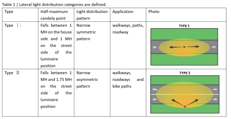
Tabelle zur lateralen Lichtverteilung von Leuchten
point | Light distribution pattern | Application | Photo Type I : | Falls between 1 MH on the house side and 1 MH on the street side of the luminaire position | Narrow symmetric pattern | walkways, paths, roadway | TYPE 1 Type II | Falls between 1 MH and 1.75 MH on the street side of the luminaire position
in „Neue Bauteile: Energiemanagement, optische Datenübertragung und mehr“ · Mikrocontroller und Digitale Elektronik · · Screenshots
-
 Bild
Bild
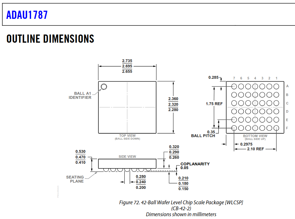
Geometrische Abmessungen eines WLCSP-Gehäuses
ADAU1787 OUTLINE DIMENSIONS BALL A1 IDENTIFIER TOP VIEW (BALL SIDE DOWN) 2.735 2.695 2.655 2.360 2.320 2.280 0.285 7 6 5 4 3 2 1 1.75 REF 0.35 BALL PITCH BOTTOM VIEW (BALL SIDE UP) 0.2975 2.10 REF SIDE VIEW 0.530 0.470 0.410 0.320 0.290 0.260 COPLANARITY 0.05 SEATING
in „WLCSP Sockel? (ADAU1787)“ · Platinen · · Screenshots
-
PDF
LCD162F_DIS.pdf
5.3 V Operating voltage for LCD VDD - VO 25°C 4.5 4.8 5.1 V 50°C 4.4 4.7 5.0 V Supply voltage for side light VF --- --- 4.2 4.6 V Supply current for side light IF VF=4.2V --- 100 180 mA Input voltage ' H ' level VIH --- 2.2 --- VDD V Input voltage ' L ' level VIL --- -0.3 --- 0.6 V ◆ AC Characteristics
in „2x16 LCD-Display funkt einfach nicht“ · Mikrocontroller und Digitale Elektronik ·
-
Datei
partdb-autoprice.py
www.reichelt.de" header["Cookie"] = "USERDOMAIN=www.reichelt.de; last_viewed_articles[0]=23445; " +\ "Reichelt_SID=" + getReicheltSessionId() + "; Reichelt_PROVID=NewSID" header["Content-Type"] = "application/x-www-form-urlencoded" header["Content-Length"] = str(len(body)) http.request("POST", "/index.html?SID="
in „PART-DB RW 1.2“ · Projekte & Code ·
-
PDF
2001071338_EG-Micro-EG2132_C480660.zh-CN.de.pdf
seinMCUDas Ausgangslogiksignal ist direkt mit dem verbundenEG2132auf dem Eingangskanal. Die High-Side-High-Side- und Low-Side-Low-Side-Ausgangstreiber können bis zu sinken1,5Aund maximaler Ausgangsstrom bis zu1A,High-End-Oberarmkanal kann ertragen300VSpannung ist die Leitungsverzögerung zwischen dem
in „Probleme mit Bootstrap Halbbrücke“ · Analoge Elektronik und Schaltungstechnik ·