RATINGS (Ta = 25°C) CHARACTERISTIC SYMBOL RATING UNIT Collector−Emitter Voltage V 25 V CEO Collector−Base Voltage V 35 V CBO Collector Current I 150 mA / ch C Input Voltage VIN(Note 1) 20 V Input Current IIN(Note 2) 10 mA Power Dissipation PD(Note 3) 0.75 W Operating Temperature Topr −40~85 °C Storage Temperature
Das scheint ein ZX85 Board zu sein, vom Computerclub Jena entwickelt: https://www.robotrontechnik.de/html/computer/bausaetze.htm Ziemlich weit unten. Dein Board unterscheidet sich dadurch, das bei dir ein zweites EPROM
Leitung geht zu einem HF-Stecker. Da ist mir > nicht klar was da ausgegeben wird Wird wohl Video (BAS Signal) sein.
commutation independent on motor type or motor loading .Built-in flyback diodes .Three push-pull outputs: -0.85 A output current -built-in current limiter .Thermal protection .Low current consumption by adaptative base-drive .Tacho output without extra sensor. ..Comparator for external position generator (PG)
commutation independent on motor type or motor loading .Built-in flyback diodes .Three push-pull outputs: -0.85 A output current -built-in current limiter .Thermal protection .Low current consumption by adaptative base-drive .Tacho output without extra sensor. ..Comparator for external position generator (PG)
commutation independent on motor type or motor loading .Built-in flyback diodes .Three push-pull outputs: -0.85 A output current -built-in current limiter .Thermal protection .Low current consumption by adaptative base-drive .Tacho output without extra sensor. ..Comparator for external position generator (PG)
commutation independent on motor type or motor loading .Built-in flyback diodes .Three push-pull outputs: -0.85 A output current -built-in current limiter .Thermal protection .Low current consumption by adaptative base-drive .Tacho output without extra sensor. ..Comparator for external position generator (PG)
°C to +70°C Fully Compliant with IEEE 802.3/802.3u Stan- • Industrial Temperature Range: –40°C to +85°C dards • Available in 32-pin (5 mm x 5 mm) QFN Package • SPI with Clock Speeds up to 40 MHz for High Additional Features Throughput Applications • Supports 10BASE-T/100BASE-TX In addition to offering
Dass ein ARM so günstig zu haben ist, scheint ein Wunschtraum zu sein: ATmega8: 1,85 ( Reichelt) ARM: 4,90 Da behaupte ich doch glatt, der ARM ist mindestens doppelt so teuer.
> Dass ein ARM so günstig zu haben ist, scheint ein Wunschtraum zu sein: > ATmega8: 1,85 ( Reichelt) > ARM: 4,90 Einen LPC2101 (8KB Flash, 2KB RAM) gibts bei Reichelt für 2,50 Euro. Markus
www.amazon.de/SunFounder-ATmega2560-16AU-Board-compatible-Arduino/dp/B00D9NA4CY/ref=sr_1_3?__mk_de_DE=%C3%85M%C3%85%C5%BD%C3%95%C3%91&dchild=1&keywords=arduino+mega&qid=1601124028&quartzVehicle=1480-1518&replacementKeywords=arduino&sr=8-3 und am Montag eine Adapterplatine dazu löten ...
reduzierte die Herstellkosten drastisch. Hier findet sich das Bild eines Motherboard des Microdigital TK85 ( https://en.wikipedia.org/wiki/TK85 ), ein Clone es Zx81 aus der damaligen Zeit: http://zx81.eu5.org/imagens/hard/ay03.jpg Das sind aber deutlich mehr als 17 ICs.
M M V Collector-Emitter Breakdown I = 1.0 mA, I = 0 40 V B (BR)CEO Voltage(5) C B T 4 V Collector-Base Breakdown I = 0.1 mA, I = 0 60 V 0 (BR)CBO Voltage C E 1 — V(BR)EBO Emitter-Base Breakdown Voltage IE= 0.1 mA, C = 0 6.0 V BL Base Cut-Off Current VCE = 35 V, EB = 0.4 V 0.1 μA N N ICEX Collector Cut-Off
damit man nicht nur selbst, sondern jeder leichter durchblicken kann. In meinem Fall gibt es das kaum. 85 % des Codes ist unkommentiert. Klar, die meisten Klassen erklären sich ein wenig von selbst, aber trotzdem hilft das nicht immer. A. S. schrieb im Beitrag #5967147: > Damian K. schrieb: >> Wenn
Kein Stress, das ist immer so, wenn man sich in eine große Code Base einarbeitet, vor allem ohne Erfahrung damit. Auch wenn es so wirkt, als ob man absolut nicht mehr versteht, stimmt das nicht -- nach einiger Zeit weiß man dann plötzlich doch, was los ist.
Conditions Symbol Value Unit Collector-emitter voltage V CEO 400 V VCEW 550 V V CES 900 V Emitter-base voltage V EBO 11 V Collector current C 5 A Collector peak current ICM 7.5 A Base current B 2.5 A Base peak current IBM 4 A Total power dissipation T case 25°C Ptot 50 W Junction temperature Tj 150 °
kommen da zum Einsatz. Aber 1000A, niemals. Ohmsche Verluste steigen Stromquadratsch. Bei 300W und 85% Wirkungsgrad wären das immerhin noch 200A. (maximal, keinesfalls dauer). 1000A hätte die 25fache Verlustleistung zur Folge...
10kA sind kein problem! aaalles einstellungssache! Dann aber mit Ölkühlung: http://nforce2and3base-by-polli.info/IFA/Modding-PC11.jpg :-)
Hmmm - wieso pro cm? Ich habe doch alle Dimensionen bereits eingegeben. Oder habe ich die "finger base width" missverstanden? Meinten sie die Breite eines Fingerpaares? Aber so ist es nicht auf der Zeichnung.
durch Nachrechnen auf eine viel kleinere Kapazität als 47pF komme. C = er*e0*A/d mit er = 8,85e-12 As/Vm e0 = 4 (oder welches Material hast Du?) A = 15*25 mm² = 3,75e-4 m² für d = 1,6mm kriege ich C=8.3pF. Bei d = 0,5mm wäre es nach meiner Rechnung auch nur 27pF. noch ein PS:
hat. An jedem GPIO habe ich einen 1k Ohm Pullup Widerstand und einen Transistor BC548B. An der Base des Transistors habe ich dann wieder 1K Widerstand und wollte auf die 7 Segmentanzeige fahren (das ganze dann 14 mal) Habe also alles zusammengebastelt und die Software geschrieben. Das Problem
der richtig rum angeschlossen werden muss: https://www.reichelt.de/elko-radial-4-7-f-35-v-rm-2-0-85-c-2000h-20--rad-4-7-35-p15135.html?&trstct=pol_6&nbc=1
50mhz} -period 20.000 -waveform { 0.000 10.000 } [get_ports {clk_50mhz}] derive_pll_clocks -create_base_clocks derive_clock_uncertainty [/vhdl] Auf der Suche nach einer Lösung hatte ich schon diverse Versionen mit zusätzlichen Zeilen in dem sdc-File um irgendwelche Timing-Constraints zu erstellen
..... 0,016 beim "Slow 1200mV 85C Modell"...*g* Aber ich weiß ja jetzt mal woran ich arbeiten muss;-) Was wäre denn so ein Zielwert?
Befehlen in der erstellten Datei aufgerufen werden und den Port eines Controllers so ansteuern, dass 10BaseT-kompatible Signale erzeugt werden. Die Macros könnten in C z.B. so aussehn: #define SendeStart { asm volatile ("ldi r24 , 2"); asm volatile ("ldi r25, 1"); } #define SendeBit1 { asm volatile
SendeEnde } Alles, was man an Hardware braucht, ist ein 20MHz-Quarz, ein 8-beiniger AVR (z.B. tiny85), einen Spannungsregler, etwas Hühnerfutter und vielleicht noch ein Netzwerkkabel (einfach zerschnippeln und anlöten, falls man keine RJ45-Buchse zur Hand hat). Mit zwei Portpins geht man direkt (Widerstände
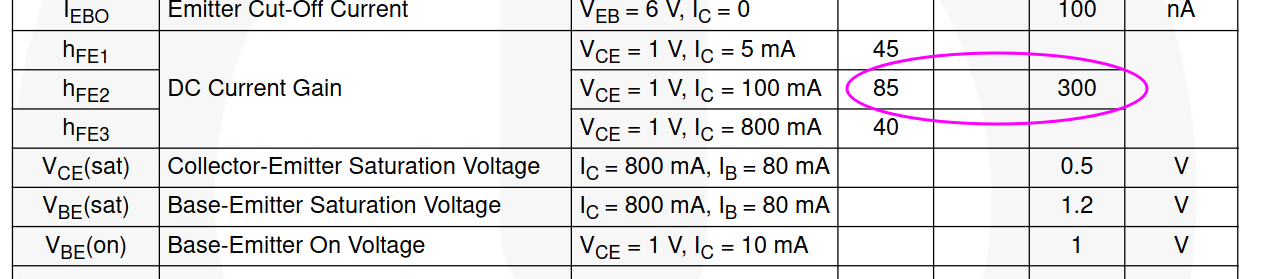
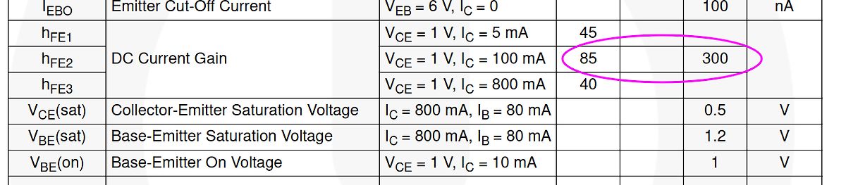
VEB = 6 V, IC = 0 100 nA
hFE1 VECE = 1 V, IC = 5 mA 45
hFE2 DC Current Gain VECE = 1 V, IC = 100 mA 85 300
hFE3 VECE = 1 V, IC = 800 mA 40
VCE(sat) Collector-Emitter Saturation Voltage IC = 800 mA, IB = 80 mA 0.5 V
VBE(sat) Base-Emitter Saturation Voltage IC = 800 mA, IB = 80 mA 1.2 V
VBE(on) Base-Emitter
must now be stored in /var/lock. The naming convention which must be used is LCK.. followed by the base name of the device file. For example, to lock /dev/ttyS0 the file LCK..ttyS0 would be created. The format used for the contents of such lock files must be the HDB UUCP lock file format. The HDB format
schreiben dürfen. Ganz einfach http://msdn.microsoft.com/en-us/library/windows/desktop/aa363858%28v=vs.85%29.aspx
SOLDERING DEVICE RANGE RANGE PACKAGE SENSITIVITY LEVEL TEMPERATURE o 28-lead QFN WM8731LSEFL -40 to +85 C 1.8 to 3.6V (Pb-free) MSL1 260°C 28-lead QFN o WM8731LSEFL/R -40 to +85 C 1.8 to 3.6V (Pb-free, MSL1 260°C tape and reel) o 28-lead QFN WM8731SEFL -40 to +85 C 2.7 to 3.6V (Pb-free) MSL1 260°C 28-lead
c0 56 6a ID 7e5e +22.7 41% seq c lowbat 0 RSSI 80 #007 1509614428 2d d4 65 f1 85 91 31 60 00 56 74 ID 65f1 +19.1 49% seq 0 lowbat 0 RSSI 65 #008 1509614432 2d d4 15 43 86 93 1d 60 a0 56 e5 ID 1543 +29.3 29% seq a lowbat 0 RSSI 80 #009 1509614434 2d d4 fe
bits: 64 Desktop: Cinnamon 4.4.8 wm: muffin dm: LightDM Distro: Linux Mint 19.3 Tricia base: Ubuntu 18.04 bionic Issue https://github.com/SensorsIot/IOTstack/issues/424#issuecomment-964144025 ist für x86_64 zu berücksichtigen.
Collector-Emitter VoltageBE= 0) 850 1000 V VCEO Collector-Emitter VoltagB (I = 0) 400 450 V VEBO Emitter-Base Voltage CI = 0) 7 V IC Collector Current 15 A ICM Collector Peak Current 30 A CP Collector Peak Current non repetitipe (t <20 s) 55 A IB Base Current 4 A I Base Peak Current 20 A BM TO-3 TO-218 ISOWATT218
Kollektor-Emitter-Sättigungsspg. ) 1 - I = 10 mA, - I = 1 mA – – 0.25 V C B - VCEsat - IC= 50 mA, - I B 5 mA – – 0.40 V Base-Emitter saturation voltage – Basis-Emitter-Sättigungsspannung ) 1 - IC= 10 mA, - I B 1 mA 0.65 V – 0.85 V - VBEsat - IC= 50 mA, - I B 5 mA – – 0.95 V Collector-Emitter cutoff current – Kollektor-Emitter-Reststrom - VCE 30 V, - V =EB V - CBX – – 50 nA Emitter-Base cutoff current – Emitter-Basis-Reststrom - VCE 30 V, - V =EB V - EBV – –- 50 nA Gain-Bandwidth Product – Transitfrequenz - I = 10 mA, - V = 20 V, f = 100 MHz f 250 MHz – – C CE T Collector-Base Capacitance
400 pA 15 10 200 pA 25 4.0 13 〉 5.0 〉 18 JFET Input D/751 Industrial Temperature Range (–25⋅C to +85⋅C) LM258 0.15 5.0 10 30 50 1.0 0.6 〉 1.5 〉 18 Split or Single Supply N/626, D/751 +3.0 +36 Op Amp Automotive Temperature Range (–40⋅C to +85⋅C) MC3358 5.0 8.0 10 75 20 1.0 0.6 〉 1.5 〉 18 Split or Single
Symbol Werte Einheit Parameter Symbol Values Unit amber blue Betriebstemperatur* Tboard, op – 40 … + 85 °C Operating temperature range* Lagertemperatur Tboard, stg – 40 … + 85 °C Storage temperature range Sperrschichttemperatur Tj 125 °C Junction temperature Durchlassstrom pro Chip DC IF 750 700 mA Forward
, the display operation to the out of display screen of User-Window should be processed under Base-Window. When Base-Window is selected even if some User-Window is defined, all of display operation is processed under Base-Window. Therefore, the current display pattern of User-Window is overwritten
TO TRANSFER 128-BYTES OF DATA TO APERIPHERAL: ..................................16 2.3.1 USB Host Base Address [01H] ............................................................................................16 2.3.2 USB Host Base Length [02H] ........................................................
Werte Einheit Parameter Symbol Values Unit true green blau Betriebstemperatur* Tboard, op – 40 … + 85 °C Operating temperature range* Lagertemperatur Tboard, stg – 40 … + 85 °C Storage temperature range Sperrschichttemperatur Tj 125 °C Junction temperature Durchlassstrom pro Chip DC Forward current per
VCES Collector-Emitter VoltageBE= 0) 1500 V VCEO Collector-Emitter VoltagB (I = 0) 700 V V Emitter-Base Voltage (I = 0) 10 V EBO C IC Collector Current 8 A ICM Collector Peak Currentp(t < 5 ms) 15 A BU208A BU508A BU508AFI TO - 3 TO - 218 ISOWATT218 P Total Dissipation at T = 25 C 150 125 50 W tot c Visol
eigentlich alle Infos zu finden: http://msdn.microsoft.com/en-us/library/windows/hardware/ff540196%28v=vs.85%29.aspx Wegen Zertifikat: Wir haben ja ein Verisign Class 3 Code Signing Zertifikat, aber irgendwie gibts auch Treiber, die damit trotzdem nicht geladen werden, zum Beispiel der original CyUSB von
schreiben, dürfte sowieso kaum jemanden interssieren. Wers dennoch genauer wissen will: HP 8660 Base Unit: http://bama.edebris.com/manuals/hp/8660/ HP 86602 1.3GHz HF Extension: http://bama.edebris.com/manuals/hp/86602/ >> Mittelt sich da nicht (bei kleinen Amplituden) diese Kap.modulation
Prinzip sollte deutlich werden). Ich war erstaunt wie stabil das Ding schwingt: von 500Khz bis 85MHz konnte ich dem jede Spule vor die Füsse werfen und bekam eine saubere & vor allem symetrische Sinusschwingung bis 2Vpp. Für mehr als 80MHz müsste man einen MOSFET mit kleinerer Gatekap. nehmen.
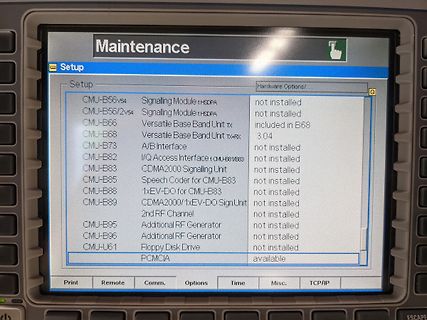
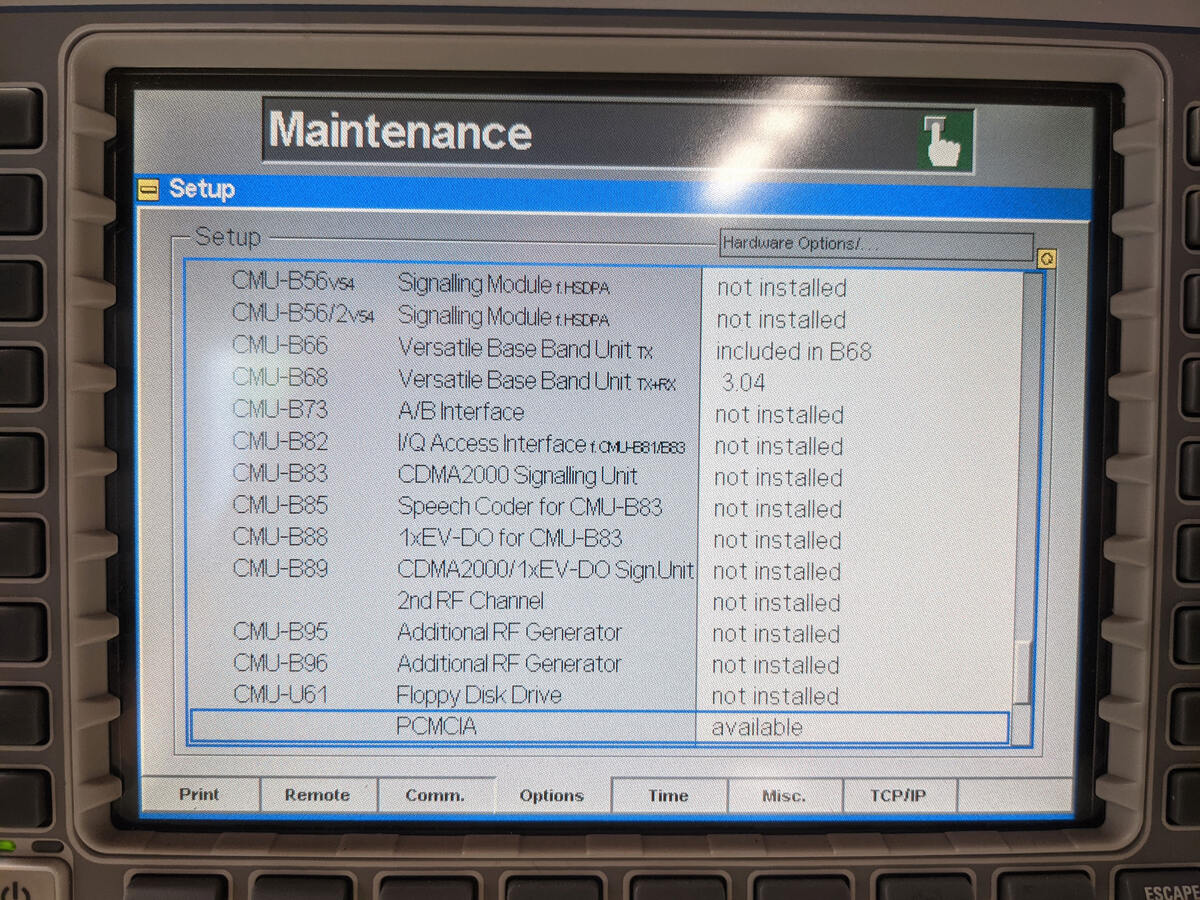
Module 1xHSDPA not installed
CMU-B56/2v54 Signalling Module 1xHSDPA not installed
CMU-B66 Versatile Base Band Unit Tx included in B68
CMU-B68 Versatile Base Band Unit Tx/Rx 3.04
CMU-B73 A/B Interface not installed
CMU-B82 I/Q Access Interface not installed
CMU-B83 CDMA2000 Signalling Unit not installed
CMU-B85 Speech Coder for CMU-B83 not installed
CMU-B88 1xEV-DO for CMU-B83 not installed
CMU-B89 CDMA2000/1xEV-DO Sign.Unit not installed
CMU-B95 2nd RF Channel not installed
CMU-B96 Additional RF Generator
Support 1b 1 = 100BASE-TX full duplex is supported by the local device 0 = 100BASE-TX full duplex is not supported 7 TX_HDX RW 100BASE-TX Support 1b 1 = 100BASE-TX half duplex is supported by the local device 0 = 100BASE-TX
Support 1b 1 = 100BASE-TX full duplex is supported by the local device 0 = 100BASE-TX full duplex is not supported 7 TX_HDX RW 100BASE-TX Support 1b 1 = 100BASE-TX half duplex is supported by the local device 0 = 100BASE-TX

 Bild
Bild
 Bild
Bild