-
Datei
ITPModul_tb.vhd
interpolation signal tb_ce : std_logic := '0'; -- start interpolation von kreis oder XYZ Satz : InversTransf ------------------------------- signal tb_calcok : std_logic := '0'; -- signalisiert alle berechnungen sind fertig signal tb_XAout : std_logic_vector(31 downto 0) := X"00000000"; --virtuelle aktuelle
-
PDF
Seiten_aus_IRFD_41840_2de.pdf
Rp is now the parallel combination of the source and load resistors. Note that the same form of transfer function describes both the series and the parallel tuned circuit. Assume now that the components in the filter of Fig. 2.15 are not ideal, but have a loss described by measurable Qu values. The equivalent
-
Datei
i2c_slave.vhd
@frank-buss.de) -- See license.txt for license -- -- I2C slave -- -- Usage: -- -- Master starts transfer: -- transfer_started is true until next stop bit -- read_mode is true (until next start or stop bit is detected), if the master wants to read data -- -- If read_mode is set: -- You can set data_out
-
PDF
GNULinux_EZUSB.pdf
the device is opened, the bulk data structure is filled in, The HexPad User Interface and a bulk transfer ioctl call is made ioctl(fd, USBDEVFS_BULK, &bulk); The HexPad application has these functional components: hexpad, getdevpath, and bulk_out. Full listings for each of these componentswillbefoundin
in „SP14Q002-A1 aus eBay - Erfahrungsaustausch“ · Mikrocontroller und Digitale Elektronik ·
-
PDF
pc715v0nszx_e.pdf
(DIN EN60747-5-2 : successor standard of DIN VDE0884 ■ Features 1. 6 pin DIP package 2. Double transfer mold package (Ideal for Flow ■ Applications 1. Home appliances Soldering) 3. Darlington phototransistor output (CTR : MIN. 600% 2. Programmable controllers at F =1mA, V CEV) 3. Personal computer peripherals
in „Optokoppler bei geringen Strömen“ · Analoge Elektronik und Schaltungstechnik ·
-
Datei
spi.h
the SPI interface // the ChipSelect Pins have to be initialized seperately void spi2_init(); // transfer 1...n bytes in both directions with using the FIFO buffer of the SPI unit --> maximum speed void spi_transfer_block(uint8_t tx_data[], uint8_t rx_data[], uint32_t block_length) ; // receive 1...n
in „SPI Code STM32F103“ · Mikrocontroller und Digitale Elektronik ·
-
PDF
GC9306_DS_V1.01.pdf
by the SPI system interface. 1)262K-Colors:18-bit/pixel(RGB 6, 6, 6 -bits input). Figure60. 1st transfer 2nd transfer 3rd transfer Input D5 D4 D3 D2 D1 D0 D5 D4 D3 D2 D1 D0 D5 D4 D3 D2 D1 D0 Data RGB R5 R4 R3 R2 R1 R0 G5 G4 G3 G2 G1 G0 B5 B4 B3 B2 B1 B0 Assignment GC9306 has data transfer counters to count the first, second, third data transfer in 6-bit RGB interface mode. The transfer counter is always reset to the state of first data transfer on the falling edge of VSYNC. If a mismatch arises in the number of each data transfer, the counter
in „Einzelne Pixel bei TFT mit GC9306/ILI9341“ · Mikrocontroller und Digitale Elektronik ·
-
PDF
MT6252.pdf
or in part is strictly prohibited. GSM/GPRS Baseband Processor Data Sheet ConfidentialA o r Reset TRANSFE‘h1EN_AUX TRleSFaRsLEe f ‘h1 TRANSFER_LEN_AUXDATA BYTES to be transferned in 1 transfer unit (excluding slave address byte) for theof transfer Cenoth depends on transfer_len, while the second read transfer length depend d i a T(NOTE)nsThe value must be set greater than 1, otherwise no transfer will take place. TRANSFER_LEN[7:0(excluding slave address byte)of DATACBYXES to be transferred in 1 transfer
in „Amparos GPS Tacker - Pollin Schnäppchen“ · Mikrocontroller und Digitale Elektronik ·
-
PDF
MPU-6050A-Register.pdf
Slave 0 are set as either read or write operations by the I2C_SLV0_RW bit. When this bit is 1, the transfer is a read operation. When the bit is 0, the transfer is a write operation. 2 I2C_SLV0_ADDR is used to specify the I C slave address of Slave 0. Data transfer starts at an internal register within
in „MPU6050 Z-Achse Keine Werte“ · Mikrocontroller und Digitale Elektronik ·
-
PDF
24LC256_32k_I2C-EEPROM.pdf
line represents valid data when, after a Start condition, the data line is stable for the Data transfer may be initiated only when the bus duration of the high period of the clock signal. is not busy. During data transfer, the data line must remain The data on the line must be changed during the low
in „immer noch EEprom“ · Mikrocontroller und Digitale Elektronik ·
-
 Bild
Bild
Logikanalysator Screenshot SPI Kommunikation
Channel 1 SPI - Enable 60.4 µs 80.02 µs L H Channel 2 SPI - Clock L H 0x30 0x21 0x2C 0x00 Channel 3 SPI - MOSI L H 0x00 0x4A 0x43 0x42 Channel 4 SPI - MISO L H
in „Arduino Uno R4: Besonderheiten und Abhilfen“ · Mikrocontroller und Digitale Elektronik · · Oszi-Bilder

-
PDF
HP_3458_A_datasheet.pdf
self-verifying auto- calibration for all functions and ranges, including ac Calibrationlab precision Superb transfer measurements •8.5 digits resolution •0.1 ppm dc Volts linearity •0.1 ppm dc Volts transfer capability •0.01 ppm rms internal noise Extraordinary accuracy •0.6 ppm for 24 hours in dc Volts •2.2 ppm
in „Gibt's einen 24-Bit DA-Wandler?“ · Analoge Elektronik und Schaltungstechnik ·
-
PDF
PDIOL_2009NOV13_PMNG_AN_01.pdf
DesignType III Compensation Network ForVoltage Mode Step-down Converters Step-Down Power Stage Transfer Function The transfer function of the power stage of the step-down converter can be determined by the voltage division: V OUT = Z OUT Eq. 1: V Z + Z IN L OUT Where Z anL Z OUT are the inductor impedance
in „Problem: SEPIC Regler, Kompensationsnetzwerk“ · Analoge Elektronik und Schaltungstechnik ·
-
PDF
DM00135183.pdf
DMA_SxCR register). 214/1323 DocID026976 Rev 2 RM0390 Direct memory access controller (DMA) 9.3.14 DMA transfer suspension At any time, a DMA transfer can be suspended to be restarted later on or to be definitively disabled before the end of the DMA transfer. There are two cases: • The stream disables the transfer
in „STM32F446 FMP I2C kein Open Drain möglich?!“ · Mikrocontroller und Digitale Elektronik ·
-
PDF
CD4514BC.PDF
the input regis- assuring transfer of data from only one register. ters can be routed into output register A, all of the next In addition to a choice of input registers, 1–16, the rate of most significant bits into register B, etc. In this way horizon- transfer of the sequential information can also be varied. tal, vertical, or other methods of data slicing can be imple- That is, if the CD4512 were addressed at a rate that is 8 mented. www.fairchildsemi.com
in „Adressierung Porterweiterung mit IC 4514“ · Mikrocontroller und Digitale Elektronik ·
-
Datei
ssd1803a_spi.c
} //***************************************************************************** // LCD - SPI Transfer // Input: - // Output: - //***************************************************************************** static inline uint8_t spi_transfer(uint8_t data) { SPDR = data; while(!(SPSR & (1<<SPIF)));
in „Initialisierung EADOGS 204-N via SPI“ · Mikrocontroller und Digitale Elektronik ·
-
PDF
Common_USB_Development_Mistakes_Cypress.pdf
retail stores all over the world, is what speed a given USB device is. There are three current data transfer speeds for wired USB. USB Low Speed transfers data at 1.5 Mbits/sec, Full Speed USB transfers data at 12 Mbit/sec, and High Speed USB transfers data at 480 Mbit/sec. Don’t get confused though: USB
in „USB-Abschirmung“ · Mikrocontroller und Digitale Elektronik ·
-
 Bild
Bild
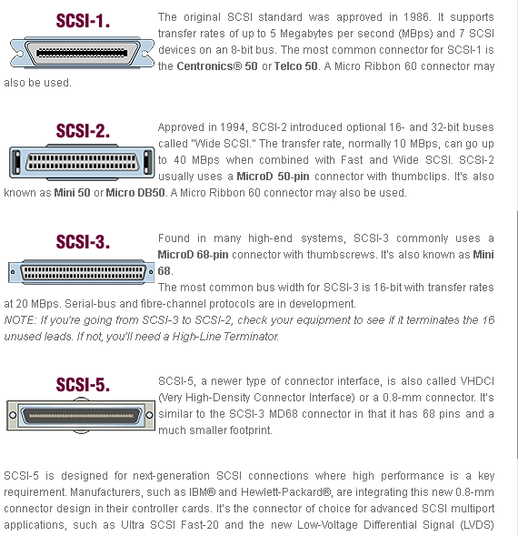
Übersicht verschiedener SCSI-Standards und Steckertypen
SCSI-1. The original SCSI standard was approved in 1986. It supports transfer rates of up to 5 Megabytes per second (Mbps) and 7 SCSI devices on an 8-bit bus. The most common connector for SCSI-1 is the Centronics® 50 or Telco 50. A Micro Ribbon 60 connector may also be used
in „SCSI von VHDCI auf Centronics. Wie?“ · PC Hard- und Software · · Screenshots
-
Datei
0001-WS2812-Block-after-ws2812_dma_start-until-finished.patch
DMA_LEDS_PER_HALFBUFF 1 #define DATA_LEN(n) ((n) * WS2812_BIT_PER_LED) // number of total bytes to transfer data #define PAUSE_LEN (WS2812_PAUSE_LEN) // number of total bytes to transfer pause #define DMA_BUF_LEN (2 * DMA_LEDS_PER_HALFBUFF * WS2812_BIT_PER_LED) // DMA buffer length: 2 LEDs @@ -382,6 +382,11
-
PDF
Q-Touch.pdf
PULL SNSK = Input SNSK = HiZ (input) SNSK = PULL SNSK = Output Cx laden SNSK = PULL SNSK = HiZ 2 Transfer SNS = OUTPUT - Low Charge Transfer SNS = OUTPUT - Low Charge Transfer 3 Read SNSK = Input Pin SNS = INPUT - HiZ if: SNSK==LOW, goto 1 SNSK prüfen, ob bereits SNSK = Input else: fertig. HIGH --> fertig
in „QTouch mit "großer" Kapazität“ · Mikrocontroller und Digitale Elektronik ·
-
PDF
Q-Touch.pdf
PULL SNSK = Input SNSK = HiZ (input) SNSK = PULL SNSK = Output Cx laden SNSK = PULL SNSK = HiZ 2 Transfer SNS = OUTPUT - Low Charge Transfer SNS = OUTPUT - Low Charge Transfer 3 Read SNSK = Input Pin SNS = INPUT - HiZ if: SNSK==LOW, goto 1 SNSK prüfen, ob bereits SNSK = Input else: fertig. HIGH --> fertig
in „Berührungssensor“ · Mikrocontroller und Digitale Elektronik ·
-
Datei
i2c.c
slave and acknowledges the transfer - returns true on I2C_ERROR or byte */ int i2c_GetByte(unsigned char more) { int byte; if((byte = i2c_ReadByte()) == I2C_ERROR) return I2C_ERROR; i2c_SendAcknowledge(more); return byte; } /*Send an array of bytes to the slave and acknowledges the transfer - returns number of bytes not successfully transmitted*/ int i2c_PutString(const unsigned char *str, unsigned char length) { signed char error; while(length) { if((error = i2c_PutByte(*str)) == I2C_ERROR
in „Serielle Verbindung 2-er PICs“ · Mikrocontroller und Digitale Elektronik ·
-
Datei
i2c.c
from the slave and acknowledges the transfer * - returns true on I2C_ERROR or byte */ int i2c_GetByte(unsigned char more) { int byte; if((byte = i2c_ReadByte()) == I2C_ERROR) return I2C_ERROR; i2c_SendAcknowledge(more); return byte; } /* * Send an array of bytes to the slave and acknowledges the transfer * - returns number of bytes not successfully transmitted */ int i2c_PutString(const unsigned char *str, unsigned char length) { signed char error; while(length) { if((error = i2c_PutByte(*str)) ==
in „PIC 16F877 und PIC 16F688 per I2C verbinden.“ · Mikrocontroller und Digitale Elektronik ·
-
Datei
spi_send.c
DMA_EnableChannel( Channel1 ); ir_init(); // SS low USART_SPI_SSLow(&PORTC, PIN4_bm); delay_us( 10 ) ; //Transfer starten DMA_StartTransfer(Channel1); DMA_StartTransfer(Channel0); delay_us( 100000 ) ; // SS High USART_SPI_SSHigh(&PORTC, PIN4_bm); while(1){ } } // ******************************* ISR **********
in „XMEGA DMA SPI“ · Mikrocontroller und Digitale Elektronik ·
-
PDF
6n136.pdf
Input-Output CIO 0.6 pF f=1 MHz V =500 V, T = 25°C............................... 10 IO A Current Transfer Ratio V IO00 V, T =A100°C............................. 10 Storage Temperature Range....... –55°C to +125°C 6N135 CTR 16 ( 7) % IF=16 mA, VO=0.4 V, Ambient Temperature Range ...... –55°C to +100°C
in „High-speed Optokoppler“ · Mikrocontroller und Digitale Elektronik ·
-
PDF
an3017.pdf
simulation program, used to provide a reasonably detailed analysis of circuits containing active CURRENT TRANSFER RATIO vs. components such as bipolar transistors, field effect transis- FORWARD CURRENT )600 tors, diodes, opamps, and lumped components such as ( VCE=5V resistors, capacitors and inductors. Its measurement
in „LTspice - unterschiedliche Simulationsmodelle“ · Analoge Elektronik und Schaltungstechnik ·
-
PDF
SA_2013_Questionnaire.pdf
xy xx for an LTI system with impulse response h[n]? 2 Time Cont. LTI Systems • Several prototype transfer functions are known for analog filters. What are the main differences between those prototypes with respect to their frequency response? • Explain some of the prototype transfer functions in more detail
in „Linearphasigkeit Beweis“ · Analoge Elektronik und Schaltungstechnik ·
-
Datei
Spi.cpp
; SPCR = (config & 0x7F) | (1<<SPE) | (1<<MSTR); tmp = SPSR; tmp = SPDR; } //------------------ transfer ----------------------------------------------- byte SPI::transfer(byte value) { SPDR = value; while (!(SPSR & (1<<SPIF))) ; return SPDR; } byte SPI::transfer(byte value, byte period) { SPDR = value
in „Arduino + GSM-GPRS-GPS-Shield“ · Mikrocontroller und Digitale Elektronik ·
-
Datei
georg.txt
0 Endpoint Descriptor: bLength 7 bDescriptorType 5 bEndpointAddress 0x82 EP 2 IN bmAttributes 2 Transfer Type Bulk Synch Type None Usage Type Data wMaxPacketSize 0x0020 1x 32 bytes bInterval 0 Endpoint Descriptor: bLength 7 bDescriptorType 5 bEndpointAddress 0x02 EP 2 OUT bmAttributes 2 Transfer Type
in „joy-it SBC-TTL hat gar keinen CH340G“ · Mikrocontroller und Digitale Elektronik ·
-
Datei
stefan.txt
0 Endpoint Descriptor: bLength 7 bDescriptorType 5 bEndpointAddress 0x82 EP 2 IN bmAttributes 2 Transfer Type Bulk Synch Type None Usage Type Data wMaxPacketSize 0x0020 1x 32 bytes bInterval 0 Endpoint Descriptor: bLength 7 bDescriptorType 5 bEndpointAddress 0x02 EP 2 OUT bmAttributes 2 Transfer Type
in „joy-it SBC-TTL hat gar keinen CH340G“ · Mikrocontroller und Digitale Elektronik ·
-
PDF
HCPL-4731.pdf
an integrated high gain photodetector to provide an extremely high current transfer ratio between input and output. Separate pins for the photodiode and output stage results in TTL compatible saturation voltagesandhighspeedoperation.Wheredesired,the VCC and VOterminals may be tied
in „High-Side-Strom auf Low-Side spiegeln (Stromspiegel?!)“ · Analoge Elektronik und Schaltungstechnik ·
-
PDF
MFRC522.pdf
NXP Semiconductors MFRC522 Standard performance MIFARE and NTAG frontend 8.1.3.2 Selectable UART transfer speeds The internal UART interface is compatible with an RS232 serial interface. The default transfer speed is 9.6 kBd. To change the transfer speed, the host controller must write a value for the
in „Schlüsselcodes in EEPROM identifizieren“ · Fahrzeugelektronik ·
-
PDF
Datasheet_MFRC522.pdf
NXP Semiconductors MFRC522 Standard performance MIFARE and NTAG frontend 8.1.3.2 Selectable UART transfer speeds The internal UART interface is compatible with an RS232 serial interface. The default transfer speed is 9.6 kBd. To change the transfer speed, the host controller must write a value for the
in „IRQ am RFID RC522“ · Mikrocontroller und Digitale Elektronik ·
-
PDF
ATS2503.pdf
Reset DMA1 TC IRQ enable. 7 0: Disable IRQ. R/W 0 1: Enable IRQ when DMA1 finishes the whole block transfer. DMA1 Half Transfer IRQ enable. 6 0: Disable IRQ. R/W 0 1: Enable IRQ when DMA1 finishes half of the block transfer. DMA1 Continue Block Transfer enable. 0: Disable continuous block transfer mode
in „Hilfe gesucht zum IC "ATS2503"“ · Mikrocontroller und Digitale Elektronik ·
-
Datei
stm32f10x.h
Channel 7 Global interrupt flag */ #define DMA_ISR_TCIF7 ((uint32_t)0x02000000) /*!< Channel 7 Transfer Complete flag */ #define DMA_ISR_HTIF7 ((uint32_t)0x04000000) /*!< Channel 7 Half Transfer flag */ #define DMA_ISR_TEIF7 ((uint32_t)0x08000000) /*!< Channel 7 Transfer Error flag */ /*************
in „COIDE 2.7.0 und STMF103C8T6 (china board), startprobleme“ · Mikrocontroller und Digitale Elektronik ·
-
Datei
spi_22.txt
Routine ; The value stored in register r16 is transferred to the master device, and when the ; transfer is completed the data received from the master is stored back into r16. ;The loop is repeated until the USI Counter Overflow Flag is set; see DATASHEET p.70 sbi PortB, 6 ; TEST LED out USIDR,r16 ;
in „Slave SPI Interrupt Service Routine für ATtiny26“ · Mikrocontroller und Digitale Elektronik ·
-
Datei
i2c-hd44780.h
; #define lcd_puts(format) lcd_puts_P(PSTR(format)) #define CMD 0x00 #define DATA 0x01 void lcd_transfer_4bit(uint8_t data, uint8_t cd); #define lcd_cmd(command) lcd_transfer_4bit(command, CMD); #define lcd_data(databyte) lcd_transfer_4bit(databyte, DATA); void lcd_generatechar(uint8_t code, const uint8
in „STM32F407, I2C LCD, Initialisierung“ · Mikrocontroller und Digitale Elektronik ·
-
Datei
sketch_may03a.ino
digitalWrite(2,0); else if(String(receivedChars) == "CSH") digitalWrite(2,1); else { spival = spi_transfer(StrToHex(receivedChars)); Serial.print("Value: "); Serial.println(spival, HEX); } Serial.println(" -Next Command..."); newData = false; } } } int StrToHex(char str[]) { return (int) strtol(str, 0,
in „NRF24L01 (SPI Problem) sendet nur Status“ · Mikrocontroller und Digitale Elektronik ·
-
Datei
Maple32.TXT
-> Bulk Transfer Type wMaxPacketSize: 0x0040 = 0x40 bytes bInterval: 0x00 ===>Endpoint Descriptor<=== bLength: 0x07 bDescriptorType: 0x05 bEndpointAddress: 0x81 -> Direction: IN - EndpointID: 1 bmAttributes: 0x02 -> Bulk Transfer Type wMaxPacketSize: 0x0040 = 0x40 bytes bInterval: 0x00
in „STM32 Win10 COM-Treiber“ · Mikrocontroller und Digitale Elektronik ·
-
Datei
main.c
TSCALIB_TypeDef calibdata; /* field storing temp sensor calibration data */ volatile bool flag_ADCDMA_TransferComplete; volatile bool flag_UserButton; static volatile uint32_t TimingDelay; RCC_ClocksTypeDef RCC_Clocks; __IO FLASH_Status FLASHStatus = FLASH_COMPLETE; /* Private function prototypes ---------
in „STM32L1 + Makefile. Linkerproblem?“ · Mikrocontroller und Digitale Elektronik ·
-
Datei
main.asm
********************************************************************** ;* ;* FUNCTION ;* i2c_do_transfer ;* ;* DESCRIPTION ;* Executes a transfer on bus. This is only a combination of i2c_read ;* and i2c_write for convenience. ;* ;* USAGE ;* i2cadr - Must have the same direction as when i2c_start was
in „Probleme mit DS1307 und dessen Zeitausgabe“ · Mikrocontroller und Digitale Elektronik ·
-
Datei
main.asm
********************************************************************** ;* ;* FUNCTION ;* i2c_do_transfer ;* ;* DESCRIPTION ;* Executes a transfer on bus. This is only a combination of i2c_read ;* and i2c_write for convenience. ;* ;* USAGE ;* i2cadr - Must have the same direction as when i2c_start was
in „Probleme mit DS1307 und dessen Zeitausgabe“ · Mikrocontroller und Digitale Elektronik ·
-
PDF
STM32F746-DISCO-OSCI.pdf
running, because it triggered his interrupt – just activated for a test. ADC-Triple including DMA transfer worked also, if triggered by software flag from the timer interrupt. Finally – also after losing also some hair – found the answer here: (see “mollyandchloe1”) https://community.st.com/s/question/
in „STM32F746G-DISCO-OSCI mit WAV-Recording auf SD-Karte“ · Projekte & Code ·
-
PDF
DS3502-3122456.pdf
condition is generated by described in detail in the I C Serial Interface the master to end a data transfer with a slave. Description section. Transitioning SDA from low to high while SCL remains high generates a STOP condition. MSB LSB Repeated START condition: The master can use a 0 1 0 1 0 A1 A0 R/W
in „Anschluss des Potentiometers an den Microcontroller“ · Mikrocontroller und Digitale Elektronik ·
-
PDF
DS3502-3122456.pdf
condition is generated by described in detail in the I C Serial Interface the master to end a data transfer with a slave. Description section. Transitioning SDA from low to high while SCL remains high generates a STOP condition. MSB LSB Repeated START condition: The master can use a 0 1 0 1 0 A1 A0 R/W
in „Anschluss des Potentiometers an den Microcontroller“ · Mikrocontroller und Digitale Elektronik ·
-
PDF
AD9857.pdf
O are used to write the instruction byte into theAD9857.The is compatible with most synchronous transfer formats, remaining SCLK edges are for Phase 2 of the communication including both the Motorola 6905/11 SPI and Intel 8051 SSR cycle.Phase 2 is the actual data transfer between theAD9857 protocols.
in „Updatepin zur Aktivierung beschriebener Kontrollregister“ · Mikrocontroller und Digitale Elektronik ·
-
PDF
AD9857.pdf
O are used to write the instruction byte into theAD9857.The is compatible with most synchronous transfer formats, remaining SCLK edges are for Phase 2 of the communication including both the Motorola 6905/11 SPI and Intel 8051 SSR cycle.Phase 2 is the actual data transfer between theAD9857 protocols.
in „Mit MSP430F2013 parallele Datenübertragung programmieren“ · Mikrocontroller und Digitale Elektronik ·
-
PDF
dem16216syh-py.pdf
correct RAM data from the second, but the first data would be incorrect, as there is not time to transfer RAM data. In case of DDRAM read operation, cursor shift instruction plays the same role as DDRAM address set instruction: it also transfer RAM data to output data register. After read operation address
in „zweite Zeile eines Displays ansprechen“ · Mikrocontroller und Digitale Elektronik ·
-
PDF
Blackfin_Median.pdf
must be an odd number */ .segment/pm pmcode; .GLOBAL start_median; start_median: /* xfer loop - transfer delay line data in DM to median filter buffer in PM */ r0=dm(i1,m1); lcntr=FILTER_LEN-1, do xfer until lce; xfer: r0=dm(i1,m1), pm(i8,m9)=r0; /* transfer to filter buffer */ /* read from input buffer
in „Bildoperatoren + DSP“ · Digitale Signalverarbeitung / DSP / Machine Learning ·
-
PDF
DEM16216SYH-PY.pdf
correct RAM data from the second, but the first data would be incorrect, as there is not time to transfer RAM data. In case of DDRAM read operation, cursor shift instruction plays the same role as DDRAM address set instruction: it also transfer RAM data to output data register. After read operation address
in „PIC16F690 init vom LCD funzt nich“ · Mikrocontroller und Digitale Elektronik ·