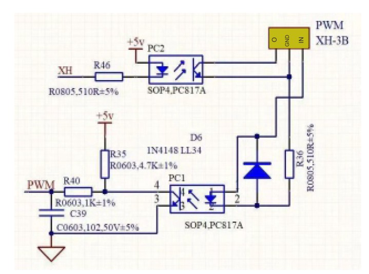
PIN FUNCTIONS REMARKS 1 Internal DC +5V Less then 50mA 2 Voltage Adjust 0 - 5V 3 Current Adjust 0 - 5V 4 Ground 5 Output OFF Short to Ground 6 N.A. 7 N.A. 8 N.A. CC current setting by remote control. Short circuit the main
Rückgabewert verwendet, denn nur dann ist klar, was eine 0 ist und dann hätte bei Fehlern auch eine 1,2 oder n zu kommen und nicht eine -1. Oder es ist ein Code, der kommt und dann heißt die Funktion bitte auch so. Aber wie oben schon gesagt: Das haben irgendwelche chaotischen Programmierer aus der Hüfte
InputClkFreq> <UIExtraClocks>0</UIExtraClocks> <MMCM_VCO>800</MMCM_VCO> <MMCMClkOut0> 1.000</MMCMClkOut0> <Pin Bank="34" PADName="V4/W4(CC_P/N)" name="sys_clk_p/n"/> Funktioniert an einem MT41....107 Gustl B. schrieb im Beitrag #7786793: > Ich verwende auf dem Board einen 100 MHz
U n 3 x 230/400 V oder 230 V Spannungsbereich 0,8 U n.. 1,15 Un Max. Strom I max ≤ 60 A oder ≤ 100 A LED - Konstante Imax= 60 A 10.000 Imp/kWh bzw. Imp/kvarh Imax= 100 A 5.000 Imp/kWh bzw. Imp/kvarh Nennstrom
can be stacked. 3. Avoid direct sunlight on the product. APPLICATION 1: NOAH 2000 (×1) +SOLAR MODULE (×2) 1. Connect DC Output Cable to NOAH 2000. 2. Attach PV Input Extension Cable to NOAH 2000. 3. Secure all cables with Cable Locker (Torque 1.5N·m). 4. Connect micro-inverter
a capacity of 1.2 GW. Resulting in a similar frequency drop reaching 49.6 Hz. - On 26th April 2023, it was the two blocks (1 and 2) of the Forsmark plant that were tripped, resulting in a loss of production of 1.0
Testanlage zur Direktreduktion von Eisen werden 140kt H2 benötigt Im Moment braucht der Standort Duisburg 1TWh, 2030 brauchen sie 10TWh = Verbrauch von Hamburg incl. Alles (Ufffff), 2040 20TWh Schiffahrt, die meisten Menschen haben begriffen, daß die Klimakrise real ist, 34Mt Treibstoff / Jahr Motorenentwicklung
be assumed, damage may occur and reliability may be affected. www.dacosemi.com.tw 5HY▯▯▯ 0D\▯▯▯▯▯ - 1 - DAC014N120Z5 Electrical Characteristics @ T C =25°C (unless otherwise specified) Parameter Symbol Conditions Min. Typ. Max. Unit OFF Characteristics Drain-Source Breakdown Voltage BV DSS VGS =0V,I D0.1mA 1200 - - V Zero Gate Voltage Drain Current IDSS VGS =0V,V =DS00V - 1 50 μA Gate-Source Leakage Current IGSS VGS =15V,V =DS - 1 200 nA ON Characteristics Gate Threshold Voltage VGS(th) VDS = VGS, D
PE2 PB2 6 31 PE1 PB3 7 30 PE0 PB4 8 29 GND PB5 9 28 AVDD PC0 10 27 PD7 PC1 11 26 PD6 PC2 12 25 PD5 3 4 5 6 7 8 9 0 1 2 3 4 1 1 1 1 1 1 1 2 2 2 2 2 C O N C C C C D D D D D P D G P P P P P P P P P D V Note: For the AVR
FREQ[6:4] (0-7) 0 0 2 4 6 8 10 12 14 16 18 20 22 24 26 28 30 32 34 36 38 40 SNR (dB) w=24, x=15, y=0, z=0 (Default) w=24, x=15, y=1, z=0 w=30, x=15, y=1, z=0 Figure 6. HiCut Controlled by SNR Metric 9 8 z H ( 7 y n e 6 q r F n 5 t s n 4 r r t 3 i t u i 2 H w = 0x1A00
Die Elektrotanya in Ungarn hat das Servicehandbuch: https://elektrotanya.com/philips_mcm207_ver.1.1.pdf/download.html#dl Demnach ist der Stereodecoder ein SI4730, im Schaltplan ein Schreibfehler "SI430" http://cdn.sparkfun.com/datasheets/Components/General%20IC/Si4730-31-34-35-D60.pdf "All three
Ich schlage vor mit Hilfe eines gezielten Lötkleckses pin1 mit pin2 des Tuner-Connectors zu verbinden: fertig mit Mono
6800 Instruction Set n l r t I a y t t h e s r C c n t x n e g t g d o c s A D B O H M E R B l A M C D 0 00000000 000 00 ! 1 00000001 001 01 NOP 1 2 No Operation 2 00000010 002 02 ! 3 00000011 003 03 ! 4 00000100 004 04 !
Frequency Minimum Typical Maximum Units Operation Frequency DC 4000 MHz 2 dB Insertion Loss DC - 2.2 GHz - 1.5 1.75 Any Bit or Bit DC ≤ 1.0 GHz ±(0.10 + 3% of atten setting)dB Attenuation Accuracy Combination - - 1.0 < 2.2 GHz ±(0.15 + 5% of atten setting)dB 1 dB Compression 1 MHz - 2.2 GHz 30 34 - dBm Input
360°). Die analytischen Lösungen der Gleichung 2cos(x−5π12)−cos(x+5π12)+sin(x+5π12)cot(5π12)=1 sind: x=arcsin(1/24−3–√−−−−−−√)−arctan(4−3–√13)+2πn,=π−arcsin(1/24−3–√−−−−−−√)−arctan(4−3–√13)+2πn,n∈Z. Die entsprechenden numerischen Lösungen im Hauptbereich [0,2π) sind: xx≈0.165 rad(≈
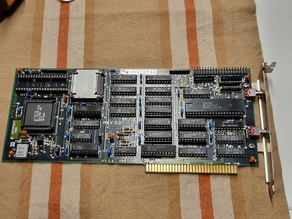
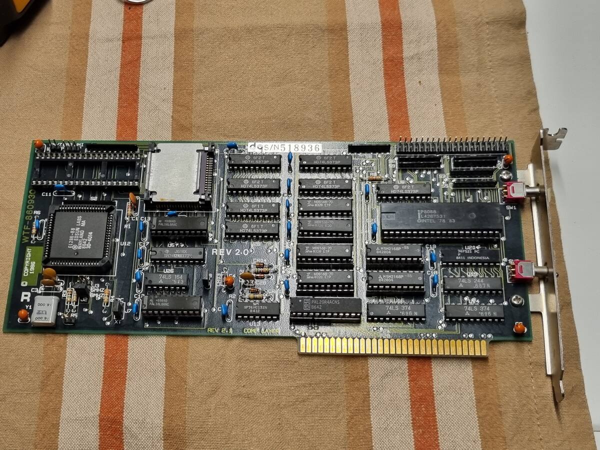
ripple counter, commonly used for frequency division and timing applications. * Motorola DM74LS244N (x2, labeled M P8918U and M P8924U): Octal buffers/line drivers with tri-state outputs. * Texas Instruments SN74LS138N: 3-to-8 line decoder/demultiplexer. * ST T74LS08B1 and T74LS10B1**: Quad 2-input
1: 1. September 2013, - Stufe 2: 1. September 2014 - Stufe 3: 1. September 2016 Die Einhaltung wird durch Marktaufsichtsbehörden zu kontrollieren; Man kann sich nur selber überlegen ob eher die Marken
auf der Platine eine kleine Gleichrichterschaltung. Die Anschlüsse Blau und Braun sind Neutralleiter(N) und Außenleiter(L1) unserer Energieversorgung mit 230V Wechselspannung. Die beiden Drähte Rot(+) und Schwarz(-) sind die Ausgänge der Schaltung. Sie führen eine Gleichspannung von mehreren 100 V und
Christoph db1uq K. schrieb im Beitrag #7769944: > Zum U327/328 gibt es auch eine Beschreibung des PCM-Protokolls Oh toll! kannst Du mir das irgendwie zukommen lassen? Evtl ist das ja kompatibel.
verwendeten IR-Protokollen gemein. Für die Darstellung der logischen 0 werden 12 Perioden der Frequenz F1=34,64kHz, für die Darstellung der 1 werden 8 Perioden der Frequenz F2=37,31kHz verwendet. Moderne Fernbedienungen (der letzten 20-30 Jahre) arbeiten mit einer konstanten Modulationsfrequenz (zwischen
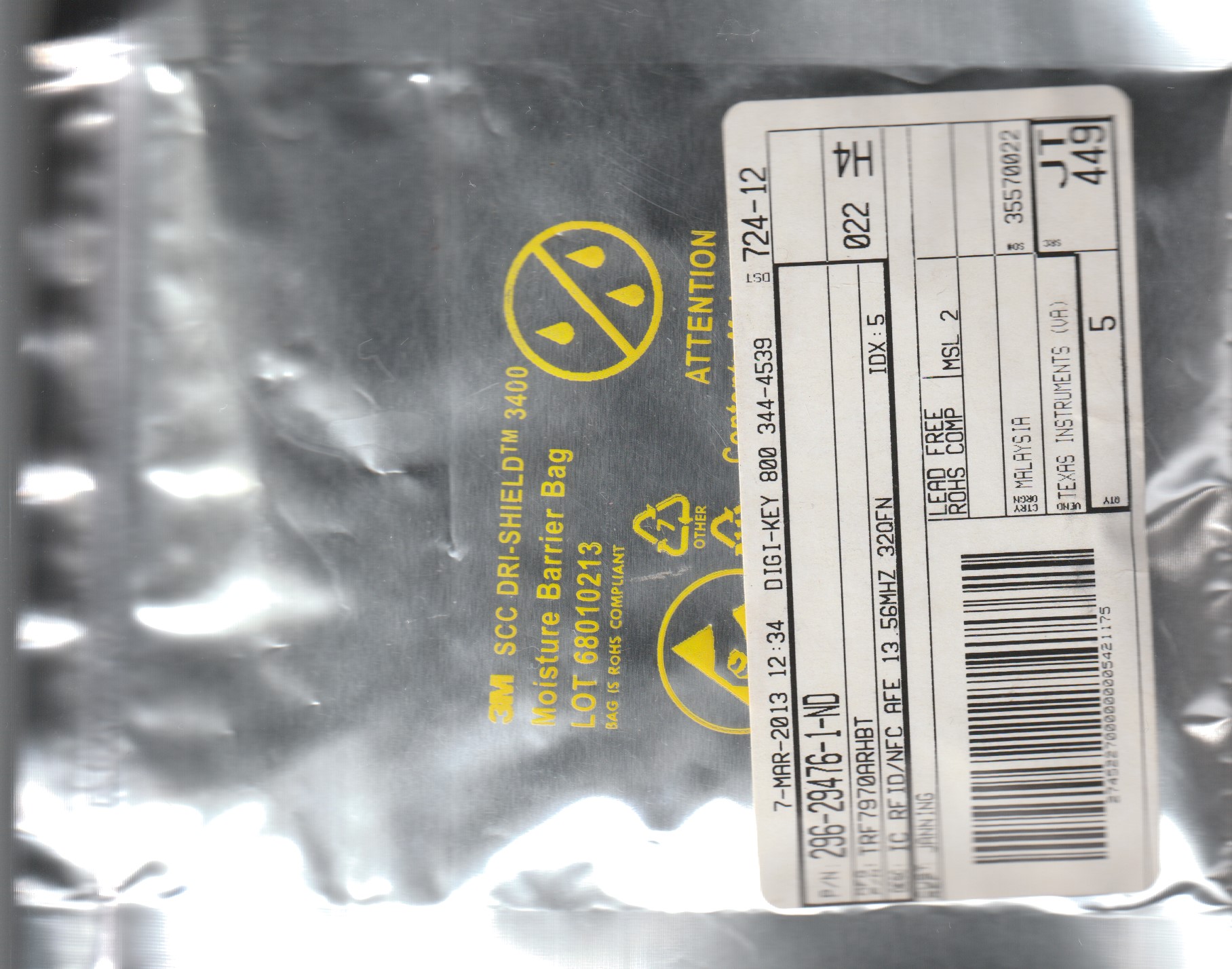
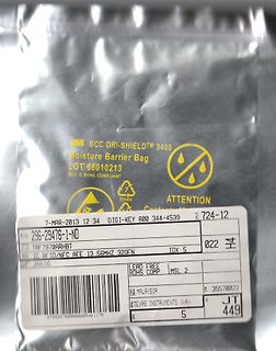
DRI-SHIELD 3400 Moisture Barrier Bag LOT 68010213 BAG IS ROHS COMPLIANT OTHER ATTENTION 7-MAR-2013 12:34 DIGI-KEY 800 344-4539 724-12 P/N 296-29476-1-ND IC RFID/NFC AFE 13.56MHZ 320FN LEAD FREE ROHS COMP MSL 2 MALAYSIA TEXAS INSTRUMENTS (VA) 35570022 JT 449
Rvlcd Cvb0B 2.2uF (0603) 5V -- Cvb1B CvsA 220nF (0603) 5V -- Cvlcd 330nF (0603) 25V O Rvlcd 3.3 ~ 10M Ohm -- Cvb0A Note 1 : O : They are necessary component -- : Please keep the place in FPC for image fine tune. Cvb0B Note 2 : System side
des Antriebes, um das Tor zu öffnen oder zu schließen, SH ufZu EL Schließverzögerung). ezA 5 EL e. N E4LLE2 G eh. M1 M2 P1 6 LED1 Ip. G P 2. 1. L Imp. DI 8 L 9 567 H W 0 ON 34 S 12 Zu LE7 OFF Au f D3 etz 5 L h . N LLED2 Ge . F ft 6 LE4 e h U ra 1 ED61 I p. G N K P L LE p. DIP FU K Im 8 SE HINWEIS! 3
das Display erfolgen Beispiele: printf("%P%l",2); // gehe zu Zeile 2 und lösche diese printf("%P%l",1); // gehe zu Zeile 1 und lösche diese, Ausgabeposition // ist jetzt 1,1 (links oben) printf("Hallo\n\rWelt"); // in der ersten Zeile erscheint "Hallo", dann erfolgt // ein linefeed \n gefolgt von einem
yellow) dom — C—rrosion Robustness Class: 3B — E—D: 2 kV acc. to ANSI/ESDA/JEDEC JS-001 (HBM) e n n c i D 1 Version 1.2 | 2019-07-22 LY T670 Ordering Information Type Luminous Intensity Ordering Code I = 10 mA F Iv LY T670-J1L2-26 4.5 ... 18.0 mcd Q65110A2175 e n n c i D 2 Version 1.2 | 2019-
https://www.cnc-shop.mobasi.com/Ersatzteile/Optimum-Bohrmaschinen-Ersatzteile/Tauschsteuerung-B-16-30-34-BF30-46-D240::17012.html Die akzeptieren wohl keine verbastelte Steuerung für den Tausch.
900 1000 1100 1200 1300 Temperatur °F 212 392 572 752 932 1112 1292 1472 1652 1832 2012 2192 2372 1,00 1,01 1,01 1,02 1,03 1,04 1,04 1,05 1,05 1,06 1,06 1,06 1,06 Ct n WÄRMEAUSDEHNUNGSKOEFFIZIENT b g u Temperatur °C Wärmeausdehnung x 10 /K-6 n g 20–250 11 e r v 20–500 12 l t 20–750 14 e r ( 20–1000
. Florian O. schrieb im Beitrag #7766512: > der Gain ist auf 1 eingestellt Auf S. 34 steht ganz oben, was die anderen Bits im 32-Bit Register bedeuten. Bit[0:3] = 0 (Bit 0...6 würde ich es aus der Grafik so interpretieren.) Bit[4:6] = noise Bit[7:27] = Data
ADI_ADC_TypeDef *pPort) ==========Reads the ADC status. @param pPort :{pADI_ADC0, pADI_ADC1} - pADI_ADC0 for ADC0. - pADI_ADC1 for ADC1. @return ADC data (ADCxDAT). MSb of data is bit 27. Bits 28 to 31 give extended sign. \n Value of 0x0fffffff => VRef. \
foo Replace V(<node>) with V(out) or V(n001) Replace<freq>with 1000 for freq = 1kHz .end end of netlist; required; added by netlister .end <required value> <foo> avalue Replace<Tstop>with 2 for stop time = 2s .ends end of subcircuit definition
die aufbereitete Digitalinformation bereitstellen. n. c. n. c. Betriebsspannung Lade-C (Regelverst.) Ausgang Kornparatorschwelle Kurzdaten der Schaltkreise UE 2124/2125 :1,2...1,4...2,2 v Bild 2: Blockschaltung des Größeren der beiden Empfänger-IC 8; der
einer Bereik Tolerantie Resolutie Marken-Familie erworben, die sich auf dem Gebiet der Mess-, Lade 4nF ± (5.0% of aflezing +5 cijfers) 1pF 40nF 10pF und Netztechnik durch besondere Kompetenz und permanente 400nF ± (3.0% of aflezing +5 cijfers) 100pF Innovation auszeichnet. 4μF 1nF 40μF 10nF Mit Voltcraft
Ding unbrauchbar geworden zu sein: 1. Messung: 2 kohm an völlig abgeschliffener LED: aber 34 Volt und blitzschnelle Überhitzung des Widerstandes 2. Messung 4,7 Kohm bei jetzt 68 Volt schnelle Überhitzung 18 Volt bei den anderen LED
Widerstand verkraftet die zusätzliche Wärme locker. Und es bleibt dann immer noch genug Spannung für U1 übrig. Durch einen evtl. Austausch des 620nF Kondensator durch einen 470nF Kondensator, kann man sich nämlich danach nicht mehr sicher sein!

 Bild
Bild
 Bild
Bild
 Bild
Bild
 Bild
Bild
 Bild
Bild
 Bild
Bild
 Bild
Bild
 Bild
Bild
 Bild
Bild
 Bild
Bild

 Bild
Bild