-
PDF
Private_Entruempelung_des_Bastel-Lagers_V2.pdf
• Zusammen 6€ #36 – ESP8266 • Diverse Module und Zubehör • Zusammen 5€ #37 – RAM • Überwiegend SO-DIMM für Notebooks • Überwiegend 1GB und 2GB Riegel • Zusammen 20€ #38 – MMR-70 FM-T ransmitter • 9 Stück vorhanden • Enthält
-
PDF
Private_Entruempelung_des_Bastel-Lagers_V3.pdf
• Zusammen 6€ #36 – ESP8266 • Diverse Module und Zubehör • Zusammen 5€ #37 – RAM • Überwiegend SO-DIMM für Notebooks • Überwiegend 1GB und 2GB Riegel • Zusammen 20€ #38 – MMR-70 FM-T ransmitter • 9 Stück vorhanden • Enthält
-
PDF
Private_Entruempelung_des_Bastel-Lagers_V4.pdf
• Zusammen 6€ #36 – ESP8266 • Diverse Module und Zubehör • Zusammen 5€ #37 – RAM • Überwiegend SO-DIMM für Notebooks • Überwiegend 1GB und 2GB Riegel • Zusammen 20€ #38 – MMR-70 FM-T ransmitter • 9 Stück vorhanden • Enthält
-
Bild
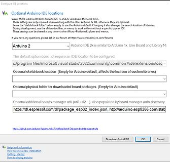
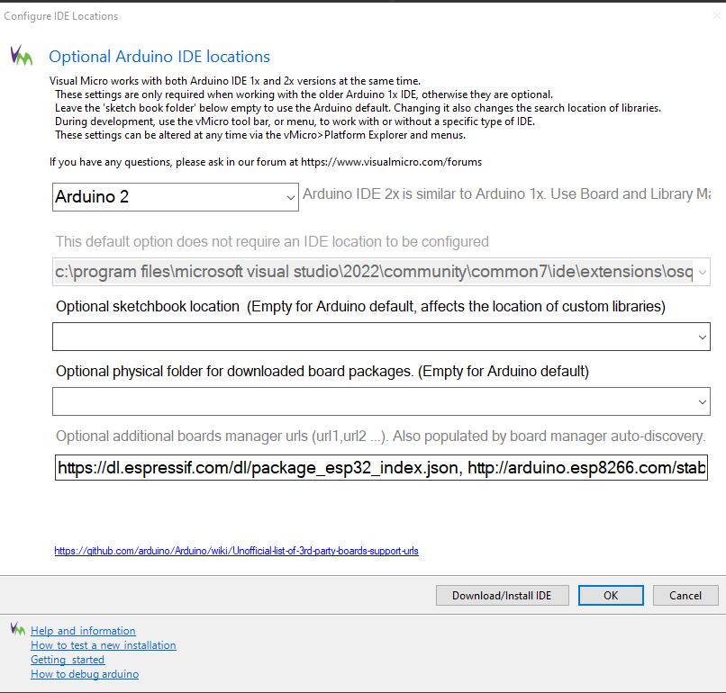
Konfigurationseinstellungen für Arduino IDE in Visual Micro
url1,url2...). Also populated by board manager auto-discovery. https://dl.espressif.com/dl/package_esp32_index.json, http://arduino.esp8266.com/stab Download/Install IDE OK Cancel Help and information How to test a new installation Getting started How to debug arduino
in „visual studio 2022 kein boardmanger zu installieren“ · Mikrocontroller und Digitale Elektronik · · Screenshots
-
Bild
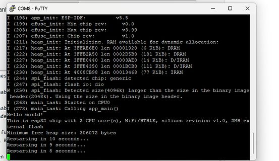
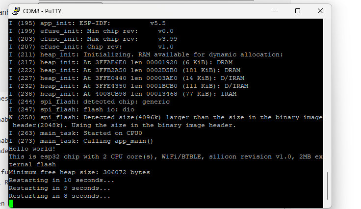
PuTTY Terminal Ausgabe ESP-IDF Bootvorgang
COM8 - PuTTY I (195) app_init: ESP-IDF: v5.5 I (199) efuse_init: Min chip rev: v0.0 I (203) efuse_init: Max chip rev: v3.99 I (207) efuse_init: Chip rev: v1.0 I (211) heap_init: Initializing. RAM available for dynamic allocation: I (
in „Keine Kommunikation zu esp32 möglich“ · Mikrocontroller und Digitale Elektronik · · Screenshots
-
PDF
Last_board.pdf
I-NOTAUS_4 INPUT-OC-ALARM-IN-4 CURRENT_4 OVCURRENT_I_IN_4 3 OVERCURRENT-PROTEKTION1 3 +3V3 + PIC-ALARM-IN ESP_ALARM ESP-ALARM-IN DGND 3 V DGND +3V3 + DGND DGND E E Last_board 19.04.2020 11:20 Sheet: 1/1 1 2 3 4 5 6 7 8 19.04.2020 11:24 D:\Arbeit\Git\E-Last\03_Schaltplan\01_Eagle\Last_board.sch (Sheet: 1/1)
in „Schaltplankontrolle Last- + HMI-Board“ · Mikrocontroller und Digitale Elektronik ·
-
Bild
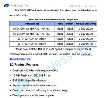
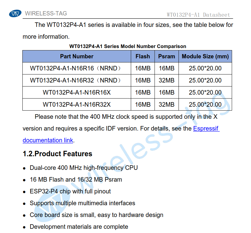
Ausschnitt eines Datenblatts für WT0132P4-A1 Module
Number Flash Psram Module Size (mm) WT0132P4-A1-N16R16 (NRND) 16MB 16MB 25.00*20.00 WT0132P4-A1-N16R32 (NRND) 16MB 32MB 25.00*20.00 WT0132P4-A1-N16R16X 16MB 16MB 25.00*20.00 WT0132P4-A1-N16R32X 16MB 32MB 25.00*20.00 1.2.Product Features Dual-core 400 MHz high-frequency CPU 16 MB Flash and 16/32 MB Psram ESP32-P4 chip with full pinout Supports multiple multimedia interfaces Core board size is small, easy to hardware design Development materials are complete
in „MicroPython-Updates, Abschaltung von 2G-Netzen, BaoChip und AI-Software“ · Mikrocontroller und Digitale Elektronik · · Screenshots
-
Bild
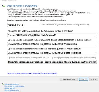
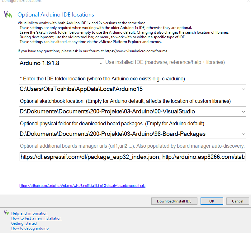
Einstellungen für Arduino IDE Pfade in vMicro
url1, url2 ...). Also populated by board manager auto-discovery. https://dl.espressif.com/dl/package_esp32_index.json, http://arduino.esp8266.com/stab https://github.com/arduino/Arduino/wiki/Unofficial-list-of-3rd-party-boards-support-urls Download/Install IDE OK Cancel Help and information How to test
in „visual studio 2022 kein boardmanger zu installieren“ · Mikrocontroller und Digitale Elektronik · · Screenshots
-
PDF
Log_12h.pdf
delay_init... board_led_init... button_init... timer2_init... wpsbutton_init... Version: 2.9.4 Hardware: STM32F103 Display: WC12h LEDs: SK6812 RGBW rtc is online eeprom is online sk6812: external pullup detected eeprom is online current eeprom version: 0x00020900 reading ir codes from eeprom DFPLAYER LOGGER ESP8266
-
PDF
PARTS_CLEARING_-_Sheet1.pdf
be shipped due to it's weight CONTACT ME VIA: partsclearing@obrplstnr.eu EVALBOARDS / BREAKOUTS STM32 VL Discovery Evaluation Board demo firmware, E01 not loaded! €5.00 2 http://www.digikey.ahttp://media.d 10€ digikey available STM32L Discovery Evaluation Board demo firmware, E02 not loaded! €7.50 1
in „[V] Rigol DS1052E, Labornetzteil, Robotikteile, Modellbau“ · Markt ·
-
Bild
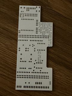
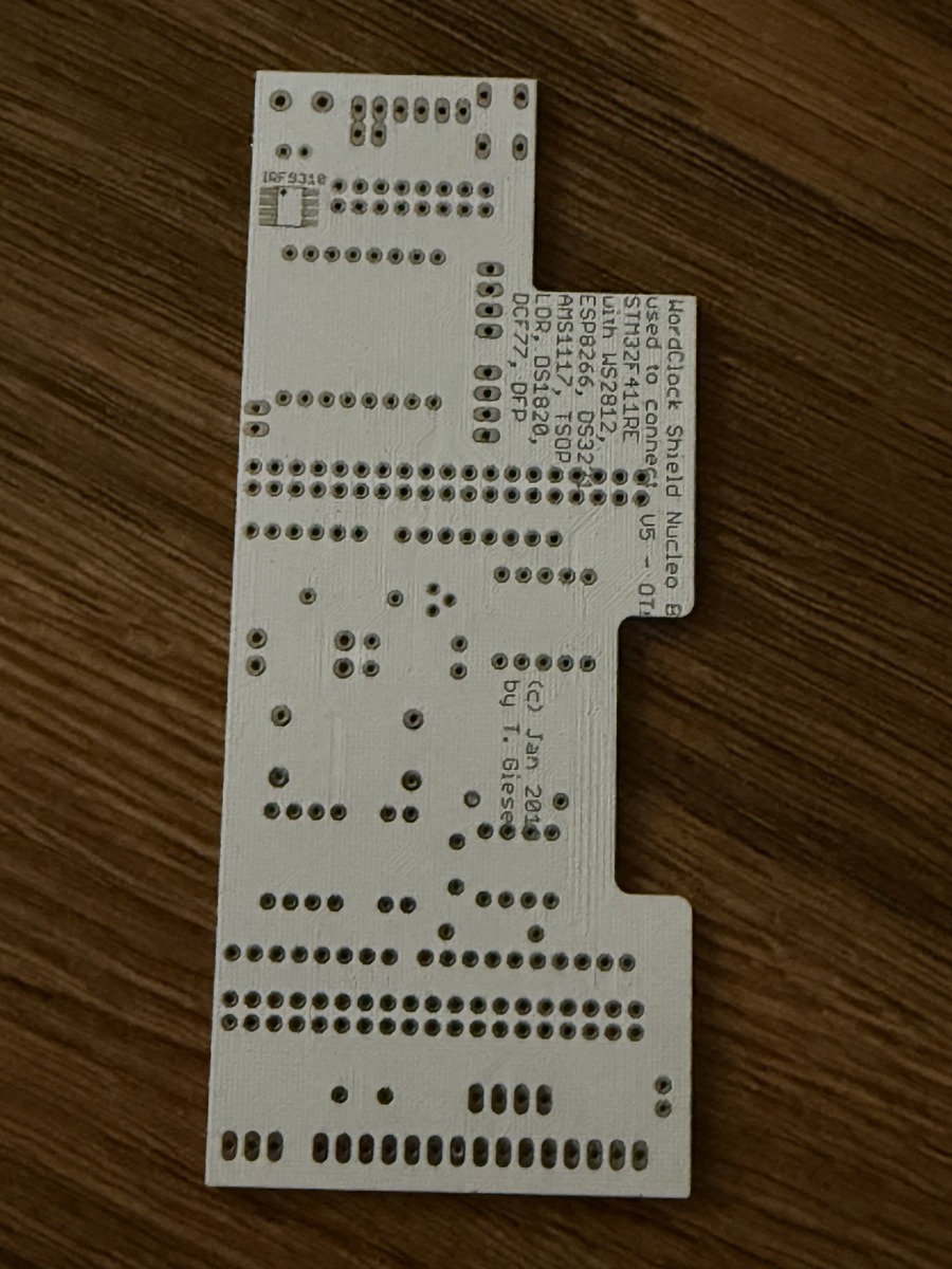
Leiterplatte Nucleo Board Clock Shield
IRF9310 WordClock Shield Nucleo B used to connect ESP8266, DS32 STM32F411RE, DS32 OR, DS1820, DCF77, DS32 U5 - 01 (c) Jan 2016 by T. Giese
in „WordClock mit WS2812“ · Projekte & Code · · Platinenfotos
-
Datei
shared_includes.h
Interrupts === * - attachInterrupt(), detachInterrupt() * * === Type Aliases === * - uint8_t, int16_t, uint32_t, etc. (from <stdint.h>) * * === Program Memory (AVR) === * - PROGMEM, F(), pgm_read_byte(), etc. * * === Board-Specific Additions === * - ESP, SAMD, etc. may add features like ESP.getFreeHeap(), etc
in „Flexible SplitText() Klasse (Anfänger)“ · Projekte & Code ·
-
Datei
shared_includes.h
Interrupts === * - attachInterrupt(), detachInterrupt() * * === Type Aliases === * - uint8_t, int16_t, uint32_t, etc. (from <stdint.h>) * * === Program Memory (AVR) === * - PROGMEM, F(), pgm_read_byte(), etc. * * === Board-Specific Additions === * - ESP, SAMD, etc. may add features like ESP.getFreeHeap(), etc
in „Flexible SplitText() Klasse (Anfänger)“ · Projekte & Code ·
-
Datei
Luxsensor_TSL2591_ESP.ino
Digital Light Sensor */ /* Dynamic Range: 600M:1 */ /* Maximum Lux: 88K */ #include <Wire.h> #include <ESP8266WiFi.h> #include <Adafruit_Sensor.h> #include "Adafruit_TSL2591.h" #include <ESP8266HTTPClient.h> #include <Float.h> #define SERIAL // wenn aktiv: Meldungen per Serial #define MAXREFRESH 300 //max
in „Lux-Sensor Adafruit TSL2591 und ESP8266“ · Mikrocontroller und Digitale Elektronik ·
-
Datei
tools.ino
----------------------------------------------- */ /* Mehr Infos hier* https://deepbluembedded.com/esp32-eeprom-library-tutorial-arduino/ */ /* Schreibe Daten ins ESP32 Flash */ void SaveDataToFlash(void *data, size_t anzahl) { EEPROM.writeBytes(0, (uint8_t *)data, anzahl); EEPROM.commit(); } void ReadDataFromFlash
in „C Programmierung: Wie komplexe Schaltwerke realisieren`?“ · Mikrocontroller und Digitale Elektronik ·
-
Datei
tools.ino
----------------------------------------------- */ /* Mehr Infos hier* https://deepbluembedded.com/esp32-eeprom-library-tutorial-arduino/ */ /* Schreibe Daten ins ESP32 Flash */ void SaveDataToFlash(void *data, size_t anzahl) { EEPROM.writeBytes(0, (uint8_t *)data, anzahl); EEPROM.commit(); } void ReadDataFromFlash
in „C Programmierung: Wie komplexe Schaltwerke realisieren`?“ · Mikrocontroller und Digitale Elektronik ·
-
Datei
PCF8574.h
PCF8574 { public: explicit PCF8574(const uint8_t deviceAddress, TwoWire *wire = &Wire); #if defined (ESP8266) || defined(ESP32) bool begin(uint8_t sda, uint8_t scl, uint8_t val = PCF8574_INITIAL_VALUE); #endif bool begin(uint8_t val = PCF8574_INITIAL_VALUE); bool isConnected(); uint8_t read8(); uint8_t
in „Fehler bei PCF8574.h Bibliotheke“ · Mikrocontroller und Digitale Elektronik ·
-
PDF
LED_Matrix_Controller_V5.pdf
Slave-Controller oder umschaltbar über einen UART Controller gelangen die Daten vom Host-Processor wie z.B. ESP32, AVR, ARM etc. in den ‚Command Controller‘. Eine sehr umfangreiche FSM modifiziert basierend auf den übertragenen Kommandos (siehe Kap. 3 - SPI and UART command protocol) die drei Speicherbereiche
in „Universeller 64x64 LED-Matrix Controller“ · Projekte & Code ·
-
PDF
ag172d.pdf
0.1uF 10K 1/16W RST BB2N/LVB0M/BB5 128 PB22 BB3P/NC/BB6 1 PB23 R405 R404 BB3N/NC/BB7 DDC_WP 3 R492 80 ESP 22K 1/16W Q402 10K 1/16W NC C421 22pF 32 NC 81 OSP XIN NC PMBS3904 20 NC 88 GPO0 X401 NC 87 GPO1 C422 VCC3.3 14.318MHz R493 NC 86 GPO2 33 XOUT NC 85 GPO3 R406 0.1uF C423 22pF 20 84 GPO4 NC 83 10K 1/
in „Geplatzte 25V-Elkos im 12V-Netzteil gegen 16V Low ESR austauschen?“ · Analoge Elektronik und Schaltungstechnik ·
-
Bild
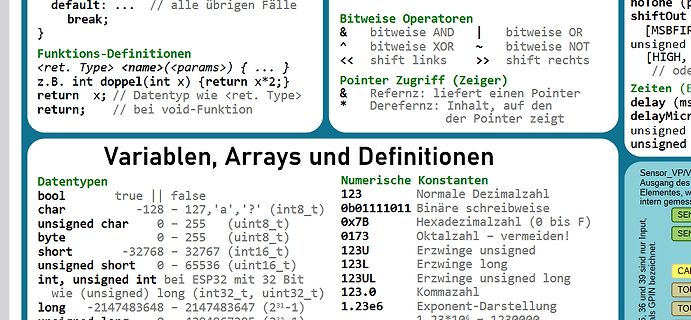
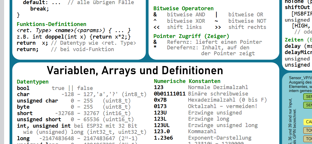
Übersicht C-Programmiergrundlagen und Datentypen
(uint8_t) short -32768 - 32767 (int16_t) unsigned short 0 - 65536 (uint16_t) int, unsigned int bei ESP32 mit 32 Bit unsigned (long) 32-bit, uint32_t long -2147483648 - 2147483647 (2^31-1) Numerische Konstanten 123 Normale Dezimalzahl 0b01111011 Binäre schreibweise 0x7B Hexadezimalzahl (0 bis F) 0173
in „ESP32 Arduino Cheat Sheet (aktuell für BSP3.x)“ · Mikrocontroller und Digitale Elektronik · · Screenshots
-
Bild
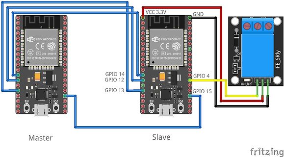
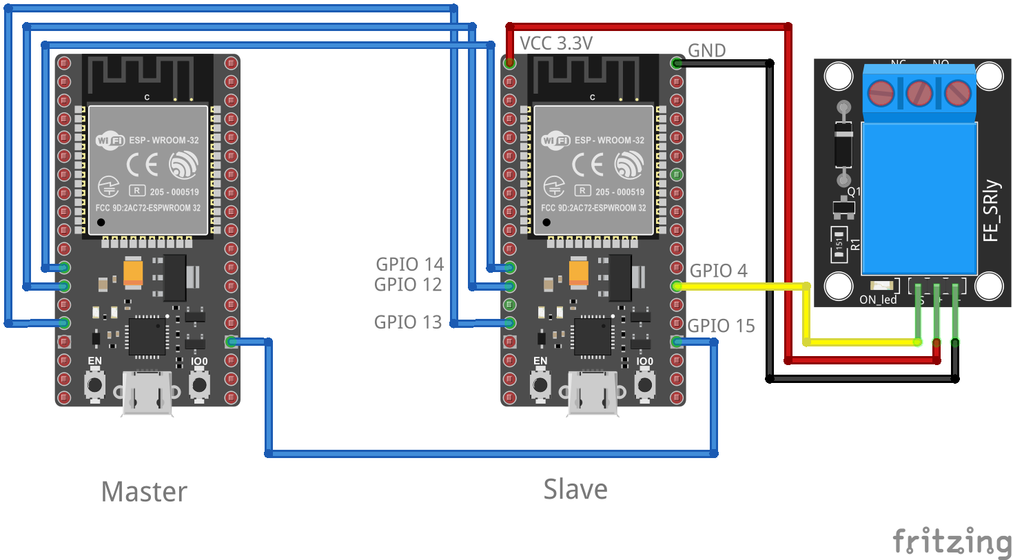
Schaltplan zweier ESP-WROOM-32 Module mit Relaismodul
VCC 3.3V GND WiFi ESP-WROOM-32 CE R 205-000519 FCC 9D:2AC72-ESPWROOM 32 GPIO 14 GPIO 12 GPIO 13 EN IO0 Master Slave GPIO 4 GPIO 15 FE_SRLY ON led R1 fritzing
in „ESP-32 SPI sendet falsche bits“ · Mikrocontroller und Digitale Elektronik · · Screenshots
-
Datei
SPI_Interrupt.ino
//Add the SPI library so we can communicate with the ADXL345 sensor #include <ESP8266WiFi.h> #include <WiFiUdp.h> #include "Arduino.h" #include <SPI.h> //Assign the Chip Select signal to pin 5. int CS=5; int interruptPin=4; volatile int loopi = 0; struct dirs{ int x; int y; int z
in „ADXL345 und ESP8266: Echtzeitdatenergassung mit konstanter Abtastrate und Interrupts“ · Mikrocontroller und Digitale Elektronik ·
-
PDF
pb_digiconnectme9210.pdf
microprocessors. ConnectME9210family. Forprofessional NET+OS software development, the Eclipse based Digi ESP™ ThekitincludesDigiESP™forEmbeddedLinux,apowerfulandfullyLinux-hosted Integrated Development Environment (IDE) with graphical user interface and IntegratedDevelopmentEnvironmentbasedontheopenEclipse
in „V] 2St. DIGI-Connect ME Module "Seriell TTL RS232 / LAN Umsetzter"“ · Markt ·
-
Bild
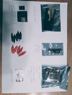
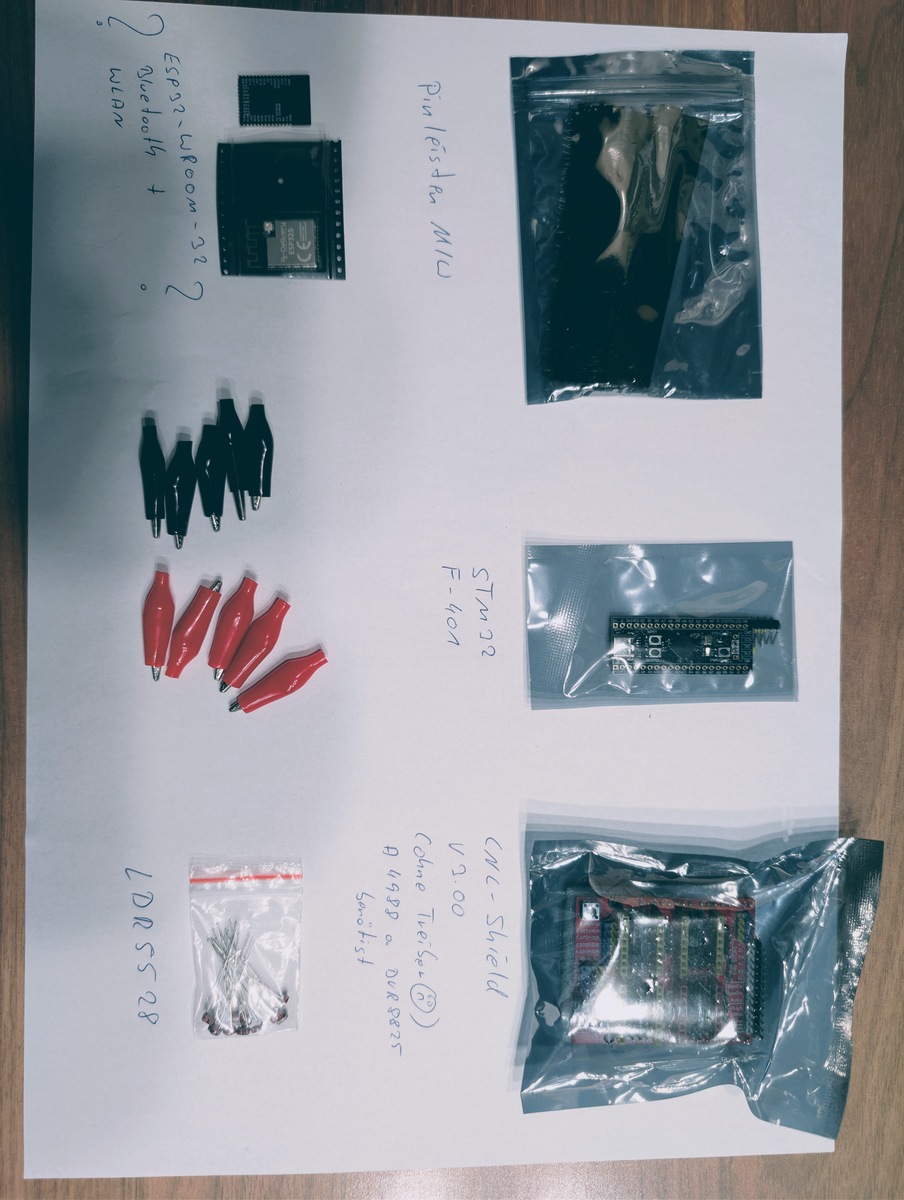
Elektronikkomponenten und Module auf weißem Untergrund
ESP32+Wroom-32 Bluetooth + WLAN Pinleiste MCU STM32 F401 CNL-Shield Arduino Clone LDR SS28
in „Wanderkiste Widlar VIII“ · Markt · · Fotos
-
Bild
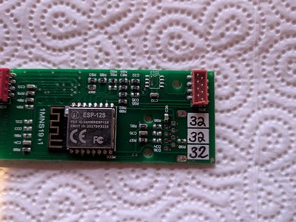
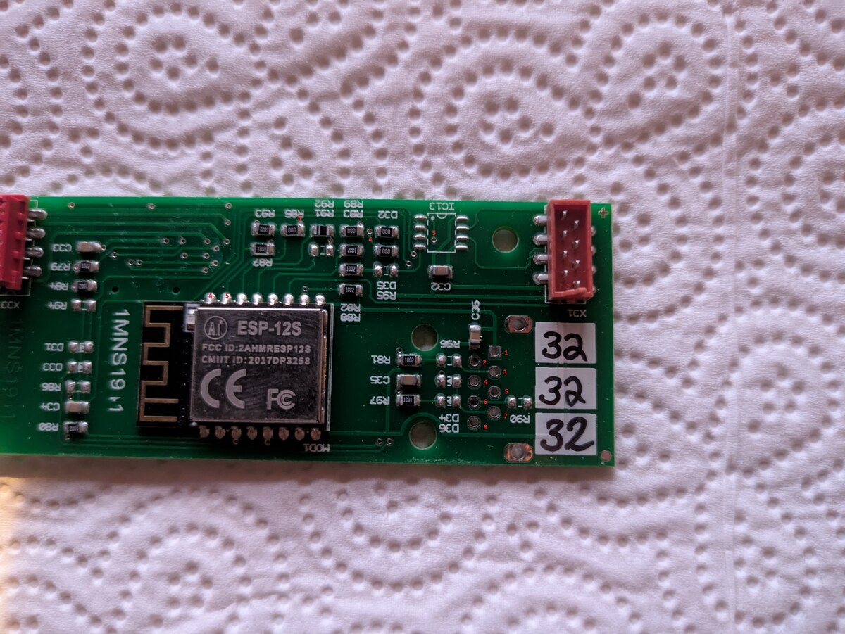
ESP-12S ESP8266 Modul auf Leiterplatte
ESP-12S FCC ID: 2AMMERESP12S CMIIT ID: 2017DP3258 CE FC 1MNS19 32 32 32 IC13 X31 MOD1
in „Richtige Bestückung eines PCB mit RJ45 Buchse“ · Mikrocontroller und Digitale Elektronik · · Platinenfotos
-
Datei
main.h
include <Adafruit_SPITFT_Macros.h> //#include <Adafruit_SPITFT.h> #include <ArduinoJson.h> #include <ESP8266WiFi.h> #include <pgmspace.h> #include <stdio.h> #include <String.h> #include <stdarg.h> #include <stdint.h> #define DEBUG /* Vereinfachtes Debug Makro fuer die debug Funktion */ #ifdef DEBUG #define
in „ESP8266, Arduino IDE ohne Arduino Overhead?“ · Mikrocontroller und Digitale Elektronik ·
-
Bild
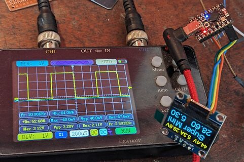
Oszilloskop mit Rechtecksignal und Messaufbau
CH1 OUT IN CH2 DIV: 1V AUTO Menu Fl Auto Ok/Ho Left Fr: 10.98KHz +Du: 64.05% Vpp: 40.0mV Rms: 67.5mV +Du: 52.68% Max: -40.0mV Vpp: 3.28V Rms: 2.11V Max: 3.12V Fr: 2.593KHz DIV: 1V X1 200uS DC DC RUN ±40V/400V Super Mini 44.4V 5.3A 28.6V 5.3A 28.6V GND VCC 3V3
in „Wie 20-40A high side (n-Ch 2,4 mOhm) bei 20-60V und 2 kHz 50% duty pwm ?“ · Analoge Elektronik und Schaltungstechnik · · Fotos
-
Datei
ESP32_C3_SPI_ADXL380_Beschleunigungstest.ino
#include <SPI.h> const int CS_PIN = 10; void setup() { Serial.begin(115200); pinMode(CS_PIN, OUTPUT); digitalWrite(CS_PIN, HIGH); // CS auf High, wenn nicht aktiv SPI.begin(6, 2, 7); // SCK, MISO, MOSI SPI.beginTransaction(SPISettings(1000000, MSBFIRST, SPI_MODE0)); // Max. 1 MHz wie empfohlen //Soft-Reset writeRegister(0x2A, 0b00000010); uint16_t softReset = readRegister(0x26); Serial.print("Soft-Reset: "); Serial.println(softReset); //Modus-Wahl writeRegister(0x26, 0b00000000); //Standby-Mode uint16_t mode1 = readRegister(0x26); Serial.print("Mode_1: "); Serial.println(mode1); writeRegister(0x27, 0b11100000
in „ADXL380 mit SPI auslesen“ · Mikrocontroller und Digitale Elektronik ·
-
Datei
esp32-can-Read-ACAN-LIB-V1.ino
//—————————————————————————————————————————————————————————————————————————————— // ACAN2515 Demo in loopback mode //—————————————————————————————————————————————————————————————————————————————— #include <ACAN2515.h> //—————————————————————————————————————————————————————————————————————————————— // MCP2515 connections: // - standard SPI pins for SCK, MOSI and MISO // - a digital output for CS // - interrupt input pin for INT //—————————————————————————————————————————————————————————————————————————————— // If you use CAN-BUS shield (http://wiki.seeedstudio.com/CAN-BUS_Shield_V2.0/) with Arduino
-
Datei
esp32-can-Send-ACAN-LIB-V1.ino
//—————————————————————————————————————————————————————————————————————————————— // ACAN2515 Demo in loopback mode //—————————————————————————————————————————————————————————————————————————————— #include <ACAN2515.h> //—————————————————————————————————————————————————————————————————————————————— // MCP2515 connections: // - standard SPI pins for SCK, MOSI and MISO // - a digital output for CS // - interrupt input pin for INT //—————————————————————————————————————————————————————————————————————————————— // If you use CAN-BUS shield (http://wiki.seeedstudio.com/CAN-BUS_Shield_V2.0/) with Arduino
-
Bild
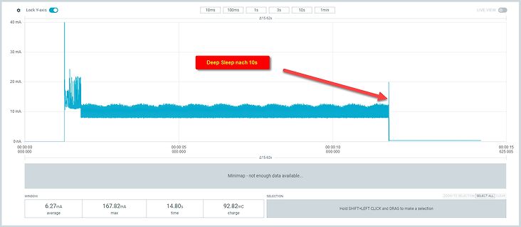
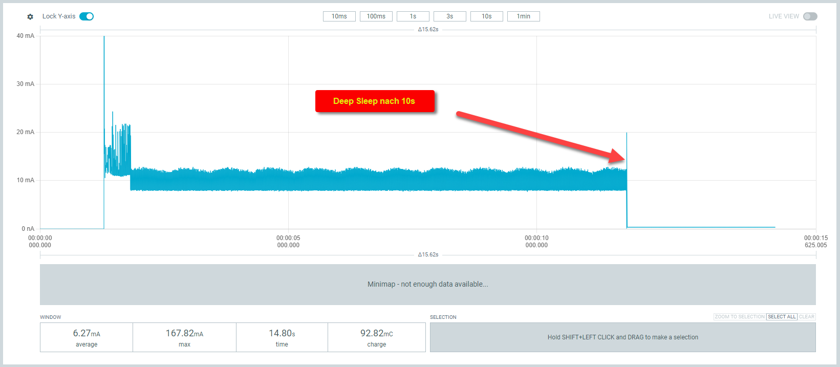
Stromverbrauchsmessung mit Deep Sleep Modus
Lock Y-axis 10ms 100ms 1s 3s 10s 1min LIVE VIEW 40 mA 30 mA 20 mA 10 mA 0 nA Deep Sleep nach 10s 00:00:00 000.000 00:00:05 000.000 00:00:10 000.000 00:00:15 625.005 Minimap - not enough data available... WINDOW 6.27mA average 167.82mA max 14.8s time 92.82mC charge SELECTION Hold SHIFT+LEFT CLICK and DRAG to make a selection ZOOM TO SELECTION SELECT ALL CLEAR
in „ESP32-H2 will nicht schlafen“ · Mikrocontroller und Digitale Elektronik · · Screenshots
-
Bild
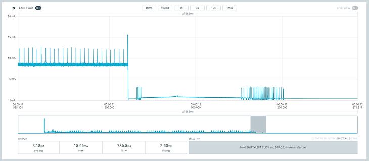
Stromverlaufsmessung in mA
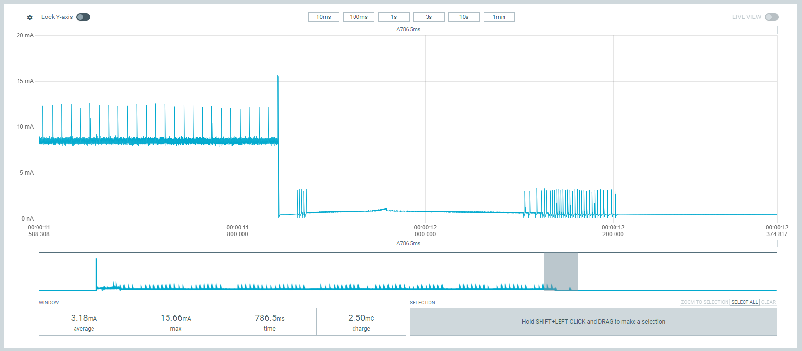
Lock Y-axis 10ms 100ms 1s 3s 10s 1min LIVE VIEW 20 mA 15 mA 10 mA 5 mA 0 nA 00:00:11 00:00:11 00:00:12 00:00:12 00:00:12 588.308 800.000 000.000 200.000 374.817 Δ786.5ms WINDOW SELECTION ZOOM TO SELECTION SELECT ALL 3.18mA average 15.66mA max 786.5ms time 2.50mC charge Hold SHIFT+LEFT CLICK and DRAG to make a selection
in „ESP32-H2 will nicht schlafen“ · Mikrocontroller und Digitale Elektronik · · Oszi-Bilder
-
Bild
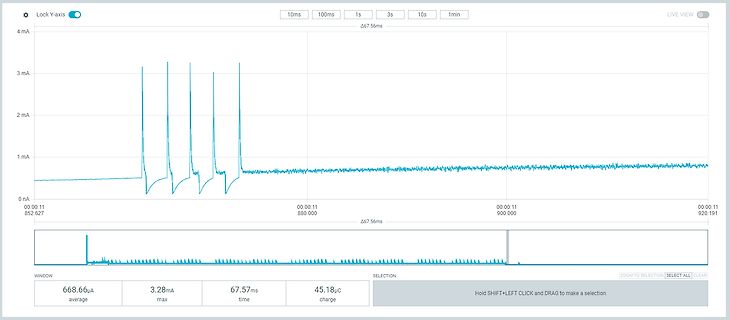
Oszilloskop-Messkurve eines Stromverlaufs
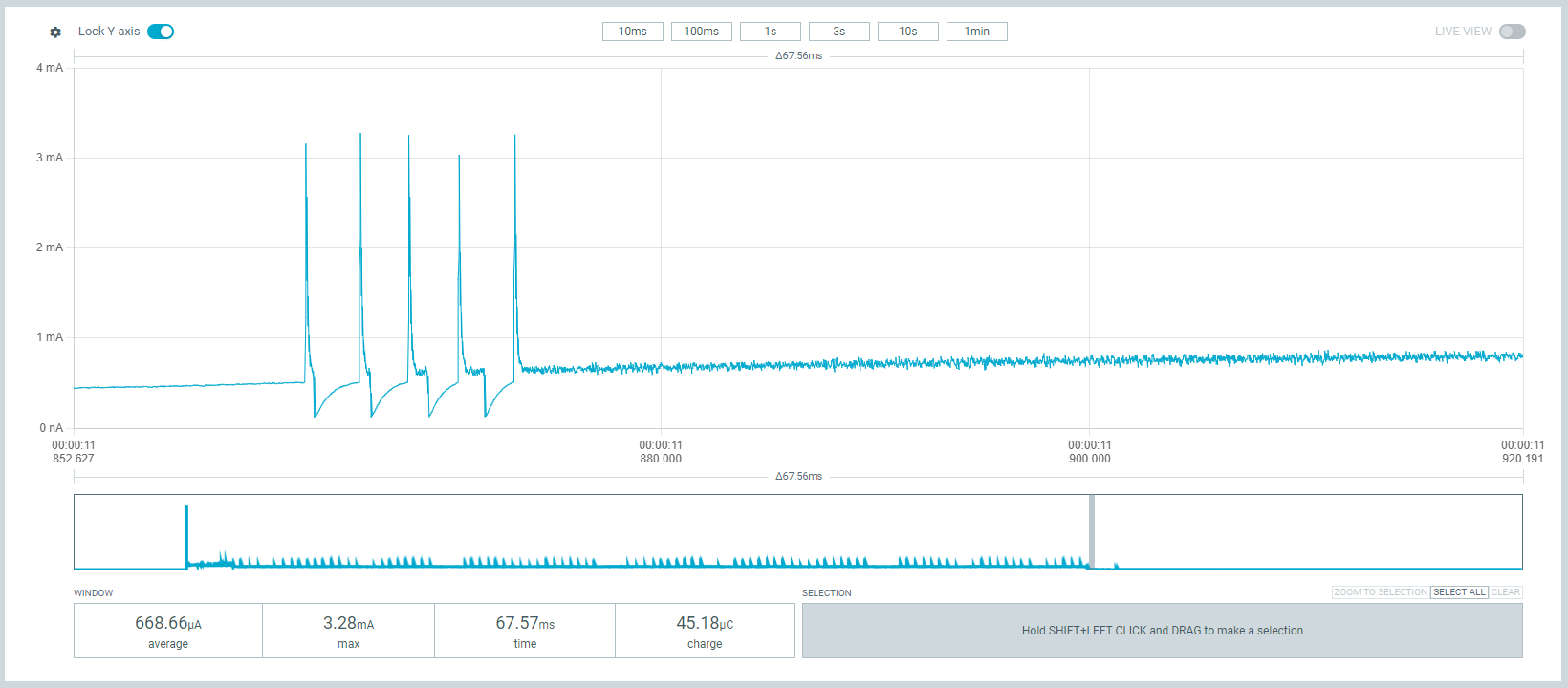
Lock Y-axis 10ms 100ms 1s 3s 10s 1min LIVE VIEW 4 mA 3 mA 2 mA 1 mA 0 nA Δ67.56ms 00:00:11 852.627 00:00:11 880.000 00:00:11 900.000 00:00:11 920.191 Δ67.56ms WINDOW SELECTION ZOOM TO SELECTION SELECT ALL CLEAR 668.66µA average 3.28mA max 67.57ms time 45.18µC charge Hold SHIFT+LEFT CLICK and DRAG to make a selection
in „ESP32-H2 will nicht schlafen“ · Mikrocontroller und Digitale Elektronik · · Oszi-Bilder
-
Bild
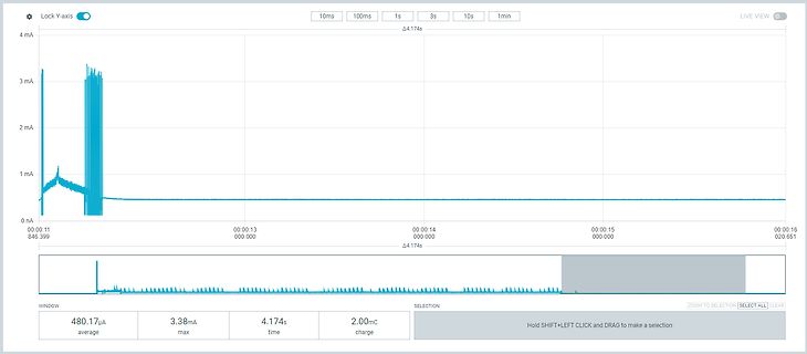
Oszilloskop-Messkurve eines Stromverlaufs
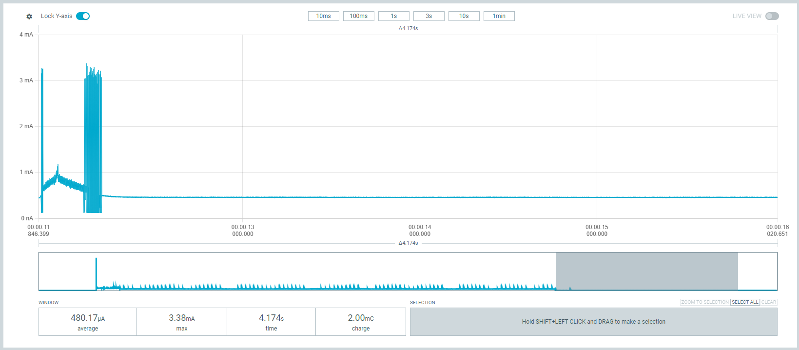
Lock Y-axis 10ms 100ms 1s 3s 10s 1min LIVE VIEW 4 mA 3 mA 2 mA 1 mA 0 nA 00:00:11 846.399 00:00:13 000.000 00:00:14 000.000 00:00:15 000.000 00:00:16 020.651 Δ4.174s WINDOW 480.17 µA average 3.38mA max 4.174s time 2.00mC charge SELECTION ZOOM TO SELECTION SELECT ALL CLEAR Hold SHIFT+LEFT CLICK and DRAG to make a selection
in „ESP32-H2 will nicht schlafen“ · Mikrocontroller und Digitale Elektronik · · Oszi-Bilder
-
Bild
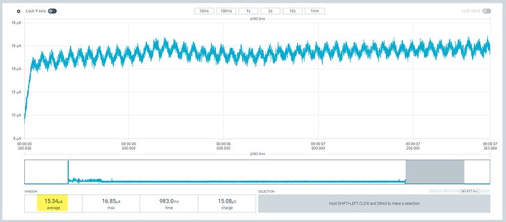
Oszilloskop-Messkurve eines Stromverlaufs in Mikroampere
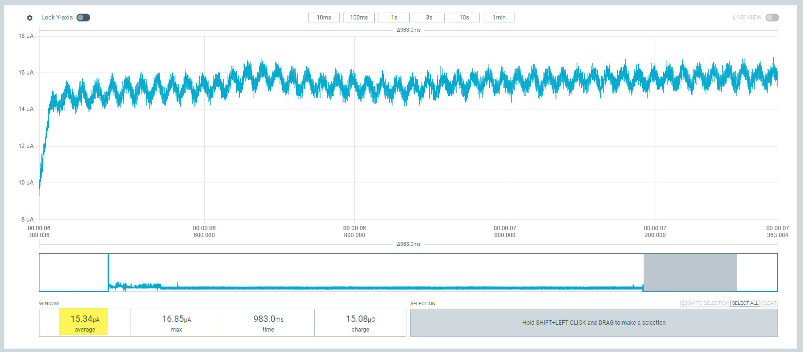
Lock Y-axis 10ms 100ms 1s 3s 10s 1min LIVE VIEW 18 µA 16 µA 14 µA 12 µA 10 µA 8 µA 00:00:06 600.000 00:00:06 800.000 00:00:06 00:00:07 000.000 00:00:07 200.000 00:00:07 363.084 Δ983.0ms WINDOW SELECTION ZOOM TO SELECTION SELECT ALL CLEAR 15.34µA average 16.85µA max 983.0ms time 15.08µC charge Hold SHIFT+LEFT CLICK and DRAG to make a selection
in „ESP32-H2 will nicht schlafen“ · Mikrocontroller und Digitale Elektronik · · Oszi-Bilder
-
PDF
pb_digiconnectme9210-1281450_1_.pdf
microprocessors. ConnectME9210family. Forprofessional NET+OS software development, the Eclipse based Digi ESP™ ThekitincludesDigiESP™forEmbeddedLinux,apowerfulandfullyLinux-hosted Integrated Development Environment (IDE) with graphical user interface and IntegratedDevelopmentEnvironmentbasedontheopenEclipse
in „[V] 18St. DigiConnect ME9210 4/8 Modules for NET+OS (12€ St.)“ · Markt ·
-
PDF
pb_digiconnectme9210-1281450.pdf
microprocessors. ConnectME9210family. Forprofessional NET+OS software development, the Eclipse based Digi ESP™ ThekitincludesDigiESP™forEmbeddedLinux,apowerfulandfullyLinux-hosted Integrated Development Environment (IDE) with graphical user interface and IntegratedDevelopmentEnvironmentbasedontheopenEclipse
in „[V] 2St. neue DIGI-Connect ME Module "Seriell / Lan Umsetzter"“ · Markt ·
-
Datei
Ziel.ino
#include <ESP8266WiFi.h> #include <WiFiUdp.h> #include <TinyGPS++.h> #include <SoftwareSerial.h> // Set WiFi credentials #define WIFI_SSID "ESP8266" #define WIFI_PASS "12345678" // Set AP credentials #define AP_SSID "Zeitanalyse" #define AP_PASS "12345678" static const int TXPin = 40, RXPin = 0; static const uint32_t GPSBaud = 9600; unsigned int portziel = 3333; unsigned int porttablet = 7777; long zeit1, zeit2, stunden, minuten, sekunden, hundertstel, gpszeit, dif, durchgang; char allBuffer[255]; char packetBuffer
in „NodeMCU-ESP8266-Board“ · Mikrocontroller und Digitale Elektronik ·
-
PDF
esp8266player2-sch.pdf
0E 1 E R TOUCH_INT GPIO16 GPIO5 CS_TOUCH C 1 I2C AUX2 20 6P 6 P $ $ SCK GPIO14 GPIO0 GLOBAL_RST GND 32 EA EO E O P P MISO GPIO12 GPIO2 CS_MEM OSCOUT 22 Q1 L T L T GPIO13 GPIO15 GND 6 RESET OSCIN 21 27.12MHz GND MOSI GLOBAL_RST VCC3 VCC GND 23 25 IRQ D1_ADR5 26 6 6 GND 2 0 30 D2_ADR4 27 5 6 R R R 1 MOSI
-
Bild
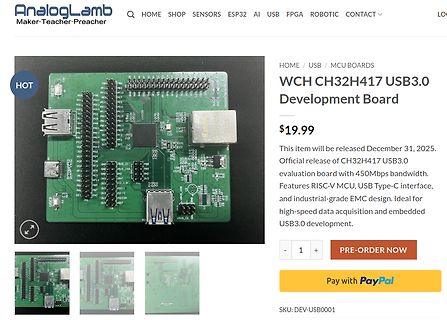
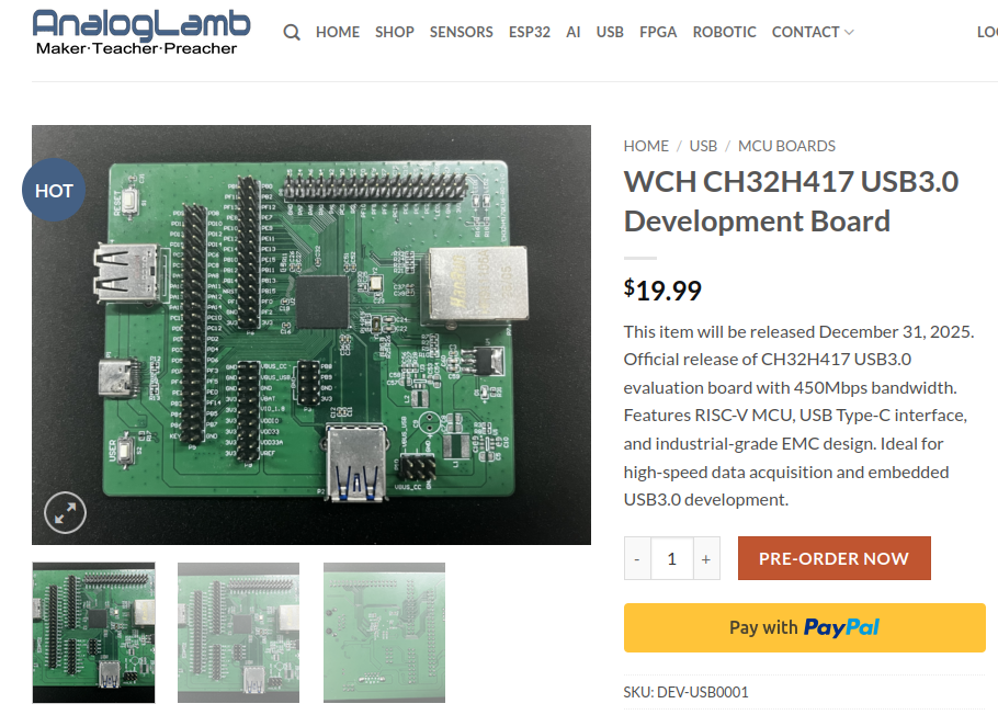
Webseite eines WCH CH32H417 USB3.0 Development Boards
AnalogLamb Maker·Teacher·Preacher HOME SHOP SENSORS ESP32 AI FPGA ROBOTIC CONTACT WCH CH32H417 USB3.0 Development Board $19.99 This item will be released December 31, 2025. Official release of CH32H417 USB3.0 evaluation board with 450Mbps bandwidth. Features
in „ESP32-E22, schneller Chip aus dem Hause WCH, ressourcensparendes WiFi 7 uvam“ · Mikrocontroller und Digitale Elektronik · · Screenshots
-
Bild
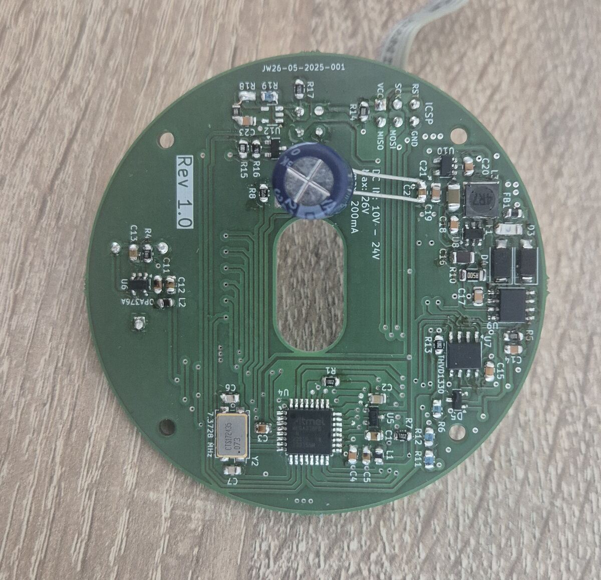
Leiterplatte mit Bestückungsdruck und Bauteilen
MOSI GND ICSP U10 C21 C20 L7 R81 D3 C8 C16 R10 D4 D1 R13 R5 C15 D7 R6 C4 C5 R12 R11 C14 R9 U5 C7 Y2 ESP32-WROOM-32E 32MHz U6 U2 L2 C11 R4 C13 Rev 1.0 R15 R16 R8 U1 24V 200mA IN
in „ATMega328PB lässt sich nur noch programmieren. Sonst keine Funktion mehr“ · Mikrocontroller und Digitale Elektronik · · Platinenfotos
-
PDF
DEVKIT1.pdf
ESP-32 NodeMCU Development Board DevKit C V4 Datenblatt Cnet: 1Faues 2Pnut 3Seccaos Pg.2 1Feaurs NdeMUsanpnsuceTpafrmEP32sareofwcotowpwer ssemo-hpSC)mrcnroeswhnegaedWF&da-mdeleot. TeEP32eesmposaeslaXesaX6mcorcsornohda-oead
in „ESP32 Devboard Serielle Schnittstelle nur wenn USB verbunden ist“ · Mikrocontroller und Digitale Elektronik ·
-
Datei
drawImages.ino
/* Simple firmware for a ESP32 displaying a static image on an EPaper Screen. * * Write an image into a header file using a 3...2...1...0 format per pixel, * for 4 bits color (16 colors - well, greys.) MSB first. At 80 MHz, screen
in „C, ESP32, Lilygo E-Ink Display "Bilder" anzeigen“ · Mikrocontroller und Digitale Elektronik ·
-
Datei
irmpsystem.h
|| defined(STM32F10X_LD_VL) \ || defined(STM32F10X_MD) || defined(STM32F10X_MD_VL) \ || defined(STM32F10X_HD) || defined(STM32F10X_HD_VL) \ || defined(STM32F10X_XL) || defined(STM32F10X_CL) // ARM STM32 # include <stm32f10x.h> # define ARM_STM32 # define ARM_STM32F10X # define F_CPU (SysCtlClockGet()) #elif defined(STM32F4XX) // ARM STM32 # include <stm32f4xx.h> # define ARM_STM32 # define ARM_STM32F4XX #elif defined(USE_HAL_DRIVER) // ARM STM32
in „IRMP - Infrared Multi Protocol Decoder“ · Projekte & Code ·
-
Datei
irmpsystem.h
|| defined(STM32F10X_LD_VL) \ || defined(STM32F10X_MD) || defined(STM32F10X_MD_VL) \ || defined(STM32F10X_HD) || defined(STM32F10X_HD_VL) \ || defined(STM32F10X_XL) || defined(STM32F10X_CL) // ARM STM32 # include <stm32f10x.h> # define ARM_STM32 # define ARM_STM32F10X # define F_CPU (SysCtlClockGet()) #elif defined(STM32F4XX) // ARM STM32 # include <stm32f4xx.h> # define ARM_STM32 # define ARM_STM32F4XX #elif defined(USE_HAL_DRIVER) // ARM STM32
in „IRMP - Infrared Multi Protocol Decoder“ · Projekte & Code ·
-
Datei
WiznetTester.ino
shield //Ethernet.init(0); // Teensy 2.0 //Ethernet.init(20); // Teensy++ 2.0 //Ethernet.init(15); // ESP8266 with Adafruit Featherwing Ethernet //Ethernet.init(33); // ESP32 with Adafruit Featherwing Ethernet pinMode(ResetEth, OUTPUT); digitalWrite(ResetEth, LOW); delay(10); digitalWrite(ResetEth, HIGH
in „Arduino und halbfunktionaler Wiznet W5500“ · Mikrocontroller und Digitale Elektronik ·
-
Datei
40.ino
#include <TinyGPS++.h> #include <ESP8266WiFi.h> #include <WiFiUdp.h> #include <SoftwareSerial.h> static const int TXPin = 4, RXPin = 5; static const uint32_t GPSBaud = 9600; unsigned int port = 2390; unsigned int port2 = 2400; long zeit1
in „NodeMCU-ESP8266-Board“ · Mikrocontroller und Digitale Elektronik ·
-
Datei
irmpsystem.h
) || defined(STM32L1XX_HD) // ARM STM32 # include <stm32l1xx.h> # define ARM_STM32 # define ARM_STM32L1XX # define F_CPU (SysCtlClockGet()) #elif defined(STM32F10X_LD) || defined(STM32F10X_LD_VL) \ || defined(STM32F10X_MD) || defined(STM32F10X_MD_VL) \ || defined(STM32F10X_HD) || defined(STM32F10X_HD_VL) \ || defined(STM32F10X_XL) || defined(STM32F10X_CL) // ARM STM32 # include <stm32f10x.h> # define ARM_STM32 # define ARM_STM32F10X #
in „IR Fernbedienung mit IRSND“ · Mikrocontroller und Digitale Elektronik ·
-
Bild
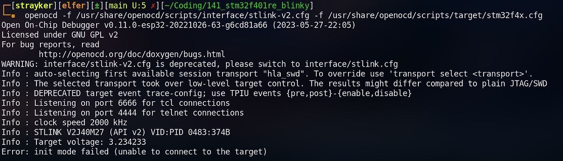
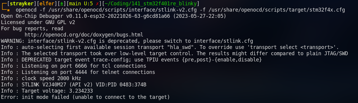
OpenOCD Terminalausgabe Fehlermeldung
strayker[elfer]~[main U:5 x]~/Coding/141_stm32f401re_blinky openocd -f /usr/share/openocd/scripts/interface/stlink-v2.cfg -f /usr/share/openocd/scripts/target/stm32f4x.cfg Open On-Chip Debugger v0.11.0-esp32-20221026-63-g6cd81a66 (2023-05-27-22:05
in „Hilfe benötigt - Debugger erkennt STM32F401RE-Mikrocontroller nicht?“ · Mikrocontroller und Digitale Elektronik · · Screenshots
-
Datei
LOADER.HTM
Protected-mode <ul> <li>CS: set to 8 (2nd GDT entry) with access to the whole 4GB range (base=0, limit=4GB, 32-bit code)</li> <li>DS, ES, SS: set to 16 (3rd GDT entry) with access to the whole 4GB range (base=0, limit=4GB, 32-bit data)</li> <li>ESP: set to the top of 640KB (ESP=000A0000h),</li> <li>EIP: set according

in „Pollin Netbox“ · Mikrocontroller und Digitale Elektronik ·