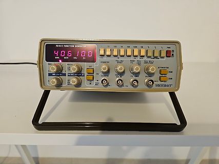
Quelle) der Angabe von 20ppm nicht wirklich vertrauen. PS: der HM8021-3 soll eine Abweichung von max. 0,5ppm haben (ob das so dann wirklich stimmt, das Gerät ist mehrere Jahre alt und nicht kalibriert worden, weiß ich natürlich auch nicht).
> "Faktencheck" für den (noch) interessierten Leser das aufgezeichnete 1 > PPS Signal eines EM-406A Moduls. Mit aktuellen GNSS Empfängern sollte das besser gehen, siehe z.B. hier ("Timing and Location Performance of Recent u-blox GNSS Receiver Modules"): https://files.tapr.org/meetings/DCC_
CHARACTERISTICS TA= 25°C, VCM = 0V unless otherwise noted. SYMBOL PARAMETER CONDITIONS VSUPPLY MIN TYP MAX UNITS VOS Input Offset Voltage ±15V 0.2 0.6 mV ±5V 0.2 0.6 mV ±2.5V 0.3 0.8 mV IOS Input Offset Current ±2.5V to ±15V 40 120 nA IB Input Bias Current ±2.5V to ±15V 120 500 nA en Input Noise Voltage
Characteristics V CC = 4.5V to 5.5V unless otherwise specified h r o a Symbol Parameter Conditions Min Max Units n l I Operating Current CS = V , SK=1.0 MHz 1 mA o C CCA IH u M ICCS Standby Current CS = V IL 50 µA s O B S IIL Input Leakage V IN0V to V CC ±-1 µA u E OL Output Leakage (Note 2) ) E P VIL Input
SSB Adjust the correct x, y coordinates (while holding one of the White point registers R, G or B on max. value) by means of 6.1 General Alignment Conditions decreasing the value of one or two other white points to the Perform all electrical adjustments under the following correct x, y coordinates (see
RAM (CGRAM): 64×8 bits (8 characters×5×8 dots) -Display Data RAM (DDRAM): 80×8 bits (80 characters max.) • Low power operation -Power supply voltage range (VDD): 2.7 to 5.5 V -LCD Drive voltage range (VDD-V5): 3.0 to 11.0 V • CMOS process • Programmable duty cycle: 1/8, 1/11, 1/16 • Character Patterns
R C R C R C R C R C C R C R C R C R C C R C R C R R C R C CC12 RR11 JW526 1 3 R JW524 CC13 C C 6 C406 4 2 TP1 R415 R416 J 5 C412 C432 C462 C461 2 C452 2 C402 C459 1 C409 C454 C404 4 C455 C405 C457 C407 C458 C408 5C456 R426 0 J 3 4 0 4 4 4 2 R 5 R447 4 R446 4 7 5 2 1 0 R JW402 R H R J 4 R 4 R J W W 2
Fix-Bracket 7.H4 Withdrawal Tool SPECIFICATION Basic Information Net Weight ≈23kg Dimensions(L*W*H) 406×235×270mm Wi-Fi Supported Wi-Fi Working Frequency 2400-2483.5MHz. Max. Wi-Fi Output Power 20.5 dBm. 2 EN Wi-Fi Transmit Bandwidth 20/40MHz. Bluetooth Supported LED Display Supported Ingress Protection
2 7:0 AMAGCNDX AM AGC Index This byte reports the current AGC gain index. 0 = Minimum attenuation (max gain) 1 – 36+ATTN_BACKUP = Intermediate attenuation 37+ATTN_BACKUP = Maximum attenuation (min gain) Note: The max index is subject to change. See Property 0x3705 AM_FRONTEND_AGC_CONTROL for details
output impedance.IC to the active area + 1/160 1/12 7.93% e 6.3% 5.7% In addition, please limit the min-max spread of RC decay to 1/160 1/11 7.77% 6.2% 5.6% be: f i | RC MAX– RC MIN | < 0.15 S VIDEO CSTN & COG applications. For LCM with r ft = 180mS ~ 200mS or smaller, bottom of the screen are uniform.e top
405 15.4.1 From Secure World to Non-secure World 405 15.4.2 From Non-secure World to Secure World 406 15.5 World Switch Log 407 15.5.1 Structure of World Switch Log Register 407 15.5.2 How World Switch Log Registers are Updated 407 15.5.3 How to Read World Switch Log Registers 410 15.5.4 Nested Interrupts
°C 1 A T = –40°C 1 A VDD = 15V TA= 25°C 1 TA= 85°C 1 TA= 125°C 1 TA= –55°C -0.8 0.8 Input current (max) TA= –40°C -0.8 0.8 V isV DD, VDD– V SS= 18V, CC ≤ TA= 25°C -0.7 ±0.2 0.7 IIN Input current V – V V = µA Input current (max) DD SS DD TA= 85°C -0.6 0.6 (max) 18V Input current (max) Input current TA= 125°C -0.55 0.55 (max) (1) Peak-to-Peak voltage symmetrical about (– V ) / 2. DD EE 5.6 Switching Characteristics TA= 25°C PARAMETER FROM TO TEST CONDITIONS VCC MIN TYP MAX UNIT 5V 20 40 V IN= VDD,rt f t = 20ns, tpd Signal
Im Datasheet der Sonde steht: - 400.15 – 406 MHz - GFSK - 4800 bit/s Die Frequency Deviation fehlt, aber laut EN 302 054 soll man 200kHz Bandbreite nehmen, dadurch ergibt sich eine Deviation von (max) 97,6 kHz. Mit dem Spectrum Analyzer (
405 15.4.1 From Secure World to Non-secure World 405 15.4.2 From Non-secure World to Secure World 406 15.5 World Switch Log 407 15.5.1 Structure of World Switch Log Register 407 15.5.2 How World Switch Log Registers are Updated 407 15.5.3 How to Read World Switch Log Registers 410 15.5.4 Nested Interrupts
extremely low ■ INPUT LEAKAGE CURRENT quiescent power over the full - V and V - DD SS DD II= 100nA (MAX) AT VDD = 18V TA= 25±C V EE supply voltage range, independent of the ■ 100% TESTED FOR QUIESCENT CURRENT logic state of the control signals. ■ MEETS ALL REQUIREMENTS OF JEDEC When a logic "1" is present
which has two extreme values along the hysteresis curve Bx,1− B x,2 B x,1− B x,2 µmin = min , and µ max = max . (5.58) H x,1Hx,2H x,1− H x,2 Hx,1,Hx,2H x,1− H x,2 Hereµ min andµ max aretheminimumandmaximumslopeofthehysteresischaracteristics. The inequality µmin ≤ µ ≤ µ max (5.59) is obvious, from which
unterwegs ist. Ich hätte da alle Kondensatoren und Widerstände im Bereich Klangregelung und C401 C402, C406 und umliegende Bauteile. mfg
defekt. 6.) Ich hätte da alle Kondensatoren und Widerstände im Bereich Klangregelung und C401 C402, C406 und umliegende Bauteile. -> Ich schaue mal nach, welche das sind. So weit, so gut.
TrueRMS DMM (PeakTech) ----------------------- U_netz = 235,5 V I_max = 1,9 A (150V*1,5A = 225W P_out) P_in = 447 W Energiekostenmessgerät zeigt an: 280 W / 0.82 cosφ Woher kommt die starke Diskrepanz? Einer von beiden lügt. Ich denke es ist das Energiekostenmessgerät
nicht-sinusförmigem AC damit noch keine Erfahrungen. Anderes billig-DMM ------------------ U_netz = 233 V I_max = 1,30 A (150V*1,5A = 225W P_out) P_in = 303 W Auh weih... welchem soll man glauben?
0.016 0.029 θ 0° 8° 0° 8° SO-8 A A2 A1 Dimensions Dimensions D Symbol In Millimeters In Inches Min Max Min Max b e A 1.370 1.670 0.056 0.068 A1 0.070 0.170 0.003 0.007 L A2 1.300 1.500 0.053 0.061 b 0.306 0.506 0.013 0.021 C 0.203 typ. 0.008 typ. D 4.700 5.100 0.192 0.208 E 3.820 4.020 0.156 0.164 E1
0.016 0.029 θ 0° 8° 0° 8° SO-8 A A2 Dimensions Dimensions D A1 Symbol In Millimeters In Inches Min Max Min Max b e A 1.370 1.670 0.056 0.068 A1 0.070 0.170 0.003 0.007 L A2 1.300 1.500 0.053 0.061 b 0.306 0.506 0.013 0.021 C 0.203 typ. 0.008 typ. D 4.700 5.100 0.192 0.208 E 3.820 4.020 0.156 0.164 E1
to to to to 18.7 x 18.7 mm 2 32 x 32 mm 2 13 x 13 mm 2 55 x 55 mm 2 20 x 20 mm 2 92 mm edge length Max. component height 6 mm 8.5 mm 8.5 mm 20 mm c 20 mm c Max. component weight 2 gr 5 gr 5 gr 25 gr 25 gr Placement force 2.4 - 5.0 N 2.4 - 5.0 N 2.4 - 5.0 N 1 - 10 N 1 - 10 N Performance 11,000 cph 8,500
PARAMETER SYMBOL UNIT MIN MAX VCC (min) to /CS Low tVSL 20 µs Time Delay Before Write Instruction tPUW 5 ms Write Inhibit Threshold Voltage V WI 1.0 2.0 V Note: 1. These parameters are characterized only. VCC VCC (max) Program,
AAA Energizer Max (Singapore) AAA Energizer Max aus IR-FB gebr. MHD 12-2030 MHD 12-2030 Kauf 10-2020 Kauf 10-2020 17. Oktober 2021 15. Mai 2024 Entladung mit: 30 mA Entladung mit: 30 mA mAh max: 1197 mAh max: 1100 Time
access is again possible in VDD Power state (and if V DD≥ 1.4 V) after the debounce time t DEB. o tDEB MAX = 1 ms, when internal voltage was always above V LOW (typical 1.2 V). VLF = 0. o tDEB MAX = 1000 ms, when internal voltage was between V LOW (typical 1.2 V) and VPOR (maximum 1.05 V). VLF = 1. See also
-Treiber-Elektronik die Sende-Stufe mit einer Art Tristate-Modus abschalten können. Beim bekannten MAX232 geht das leider nicht, dafür aber bei den Typen ICL3321 und MAX242. Tx: cmd arg0 arg1 ... argX/n Rx: cmd arg0 arg1 ... argX/n Beide verfügen über Low-Power-Shut- replyline1/n down-Modi, die sogar
are at T = 25°C. V is from7V to 80V, unless noted. (Note 3) A IN SYMBOL PARAMETER CONDITIONS MIN TYP MAX UNITS General V Supply Voltage l 7 80 V IN IIN Supply Current VIN 48V, Normal Operation Mode l 1.2 1.7 mA VIN= 12V, Shutdown Mode l 120 300 µA + + – ISENSE SENSE Input Current VIN SENSE , SENSE = 48V
Kommt aber wahrscheinlich auch auf die Baureihe an. Habe mal nach einem bezahlbaren alten 421 oder 406 gesucht, als Fahrzeug für meinen Wald. Den 404 gabs nur als Benziner, an dem habe ich bei der Bundeswehr geschraubt. Ich hatte keine Lust auf 30l Super pro 100km. Aber unter 20000 Euro gabs nur Schrott
mechanische Lüfter dreht aber immer mit - wenn auch verringert durch die thermo Kupplung die auch die max Drehzahl begrenzt. Oder der Motor ist kalt, man starte und hört erst mal nur den lauten Lüfter. Obwohl dieser garnicht gebraucht wird. Mit einem elektronischen Lüfter kann der Luftstrom je nach Bedarf
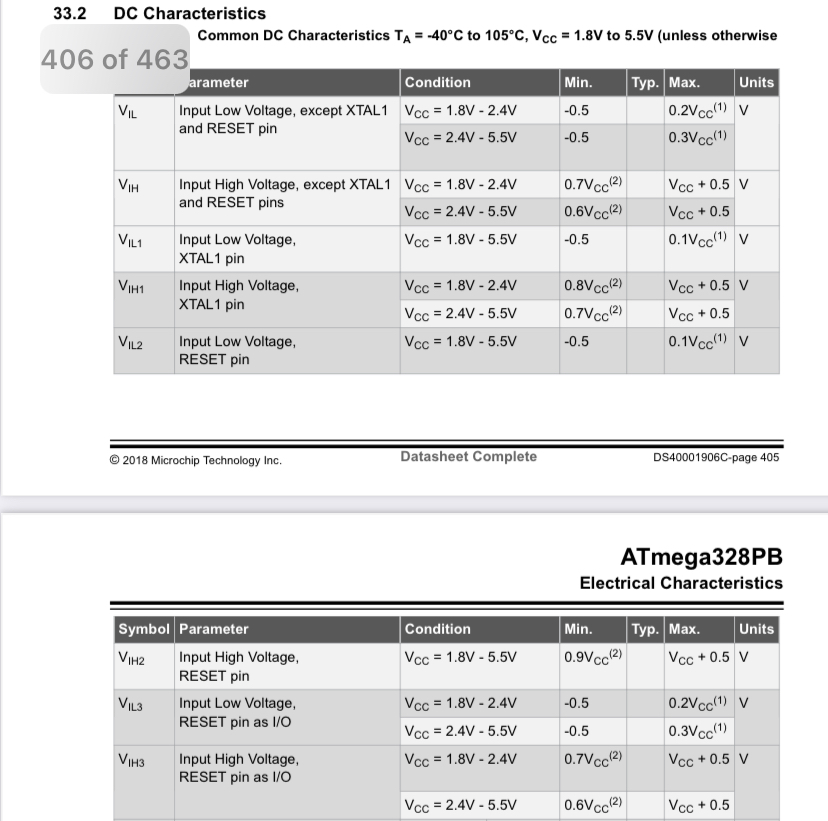
DC Characteristics
Common DC Characteristics TA = -40°C to 105°C, VCC = 1.8V to 5.5V
406 of 463
Parameter Condition Min. Typ. Max. Units
VIL Input Low Voltage, except XTAL1 and RESET pin VCC = 1.8V - 2.4V -0.5 0.2VCC(1) V
VCC = 2.4V - 5.5V -0.5 0.3VCC(1) V
VIH Input High Voltage, except
latched at the trigger to assist in point placement. There are three decimation modes: normal, min/max, and hires: H Normal (sub-sample) mode throws away samples between saved sample points. H Min/max mode saves the maximum and minimum samples over the decimation interval. H Hires mode gives extra resolution
2100h: Transmission Rate Object 2101h: Node Number 6. Encoder-specific objects 6000h to 9FFFh (DS 406)............................................................................22 Object 6000h: Operating Parameters Object 6001h: Measuring Units per revolution Object 6002h: Total measuring range in
Depth : 237 mm (9.33'') SOG (Sync On Green) Height : 428 mm (16.85'') -Min Digital 508 mm (19.99'') -Max 3-2. Video Input Signal 1) Type : R, G, B Analog 7. WEIGHT (with SPEAKER) 2) Voltage Level : 0~0.71 V Net. Weight : 8.8kg (19.40 lbs) a) Color 0, 0 : 0 Vp-p Gross Weight : 11.3kg (24.91 lbs) b) Color
I2C0 n High-Performance 32 o Crossbar Switch l r 32 I2C1 e h 32 32 32 32 r e 32 RT1 P I/O Interrupts MAX0 CONTROL MAX1 Events 32 PLL Out in EMIF dMAX Peripheral Interrupt and DMA Events 64 RX-V667/HTR-6063/RX-A700 Function Name No. TYPE (1)PULL (2) GPIO (3) Detail of Function X (P.C.B.) V R 6 1 VSS - /
großenAuflösung bleibt die dieAlias-Effektevermeidet? Schwankung ohneAuswirkung. A knapp über 2 ⋅ max D DasAbtastergebnis wirdverbessert (Dithering). B knapp über 𝑓 max C knapp unter 𝑓max AF622 Welcher Filtertyp ist geeignet,umAlias- 2 Effekte zuvermeiden,und wo ist das Filter D knapp unter 𝑓 max
eher selten. Mein CD-Player etc. ist der Grundig FineArts CD-9009 und nicht wie vermutet der PD-M406
(Ansteuern der Türöffnerspule) etwas mehr Strom. Hat tadellos funktioniert, der 9V Akku wurde mit max. 3mA geladen. Die anderen Bewohner hatten übrigens öfter ihre Haustürschlüssel abgebrochen.
Synchronous Serial Communication Mode and 4-wire Serial Bus Mode................ 405 24. LIN Module 406 24.1 LIN Module Associated Registers................................................................................................ 408 24.1.1 LINi Common Registers (i = 0, 1)......................
generated when the counter is equal to TOP. If TOP is updated to a value lower than count upon reaching MAX, the counter restarts from BOTTOM. Figure 21-3. Periodic Interrupt Mode MAX and Event) Request TOP CNT BOTTOM TOP changed to CNT set to BOTTOM a value lower than CNT 21.3.3.1.2 Time-Out Check Mode In

 Bild
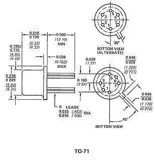
 Bild
 Bild