(pcs.) measurements 1 case /Japan 1 case /export packing (mm) Automotive 300 600 369×283×263 Use Refer to P.212 for product varieties. Refer to P.217 for product specifications. Refer to P.212 for soldering conditions. 210 Encoder 11mm Size Metal Shaft Reflow Type EC11J Series Dimensions Unit:mm PCboardmountingholedimensions
connection. AVAILABLE OPTIONS PART NUMBER LOW INTEGRATED SLOPE V PIN T MARKED AS: POWER MODE CONTROL ref A SN65HVD230 Standby mode Yes Yes VP230 SN65HVD231 Sleep mode Yes Yes –40°C to 85°C VP231 SN65HVD232 No standby or sleep mode No No VP232 2 www.ti.com SN65HVD230 SN65HVD231 SN65HVD232 SLOS346G – MARCH
der Transistor rein kommt :-) https://www.amazon.de/portal/customer-reviews/srp/-/R1YCPBVB3A5DQQ/ref=cm_cr_dp_d_rvw_ttl?_encoding=UTF8&ie=UTF8
Vorsorgung, mit einem Laser mal angeleuchtet, mal abgeblendet. > Am Ausgang sollte ein TTL Signal von 200 bis 300 kHz auftauchen. 200 bis 300 kHz mit einem Phototransistor? Träum weiter ;-)
been Stresses exceeding those listed in the Maximum Ratings table may damageDISCONTINUED. Please refer to the table on page 2 device. If any of these limits are exceeded, device functionality should not be assumed, damage may occur and reliability may be affected. Semiconductor Components Industries
30 zeigt er das Teil. https://www.roboter-bausatz.de/p/mx1508-dc-motor-treiber-modul-ln298n-1.5a?ref=ga&gad_source=1&gad_campaignid=12461217733&gclid=EAIaIQobChMIkJrupZralQMV3JKDBx2ZSBr-EAQYGCABEgL3KPD_BwE Kann das funktionieren? Grüße Bernd
zeigt er das Teil. > > https://www.roboter-bausatz.de/p/mx1508-dc-motor-treiber-modul-ln298n-1.5a?ref=ga&gad_source=1&gad_campaignid=12461217733&gclid=EAIaIQobChMIkJrupZralQMV3JKDBx2ZSBr-EAQYGCABEgL3KPD_BwE > > Kann das funktionieren? > > Grüße Bernd Moin, Das Ansteuern von Uhrwerkmodulen
The machine mode is a mandatory mode, and the other modes are optional modes. For details, you can refer to "The RISC-V Instruction Set Manual Volume II: Privileged Architecture", which is available for free download from the RISC-V International website. Table 1-3 RISC-V architecture privilege mode Code
https://www.voelkner.de/index.php?mp=products&file=info&ref=43&products_id=11864782 Braucht aber selbst ein paar "Reparaturen", sonst ist der Ripple bei 200mV und 10V störend. Sonst vom Preis/Leistung unschlagbar.
Diese Modifikation ist eine Möglichkeit den Ripple bei 200mV und 10V (Einstellung des Einganges '1X') zu entfernen/verringern. https://www.eevblog.com/forum/testgear/voltcraft-dov-series/msg6296726/#msg6296726
# Reading the content of a nRF51802 in a Hoymiles HM-800 microinverter Cross references: - Ref1: discussion on mikrocontroller.net https://www.mikrocontroller.net/topic/586015#8074969 ## Wiring ``` FT232H P500 nRF51802 (QFN48) AD0 (TCK) ───→ SWCLK 5 (
read http://openocd.org/doc/doxygen/bugs.html Info : FTDI SWD mode enabled adapter speed: 200 kHz Info : Listening on port 6666 for tcl connections Info : Listening on port 4444 for telnet connections Info : clock speed 1000 kHz Info : SWD DPIDR 0x0bb11477 Info : [nrf51.cpu] Cortex-M0 r0p0
V Coupecircuitthermique(magnétron)TC1 125°C Coupe-circuit thermique(FOUR) TC2 160°C Lampedufour OL 200–250V25WE14 Condensateur haute tension C 1,07 µF 2100 V CA Magnétron MG Filament < 1 Filament – châssis ohm. Transformateur électrique T Enroulement du filament < 1 Enroulement secondaire environ 13
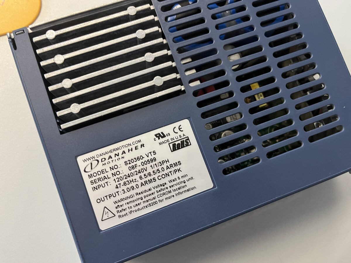
9.0 ARMS CONT/PK
WARNING! Residual Voltage. Wait 5 min after removing power before servicing unit. Refer to user manual CDROM location. Root:\Products\S200 for more information.
& 2, EEPROM, ADC, PWM 1 & 2, I/O ports peripherals and Power Bridge) occurs, causing its wake-up. Refer to Figure 12 below. Figure 13. Wait mode flow chart WAIT INSTRUCTION OSCILLATOR ON PERIPH. CLOCK ON CPU CLOCK OFF I-BIT CLEARED N RESET N INTERRUPT Y Y OSCILLATOR ON PERIPH. CLOCK ON CPU CLOCK ON I-BIT
kV on pins RXD, NSLP, TXD and INH −2 +2 kV Vesd(MM) electrostatic discharge voltage; machinnote 2 −200 +200 V model; all pins Notes 1. Equivalent to discharging a 100 pF capacitor through resistor. 2. Equivalent to discharging a 200 pF capacitor througresistor and a 0.75 H coil. In the event of a discharge
tested in Orcad’s PSPICE 10.0 which is equivalent to in a number of different simulators. Please refer to your simulator software reference manual on how to create Cadence PSPICE 15.x. The type of modeling a schematic symbol and relating a netlist to the symbol. technique that was used to model the
Fast wie oben, nur Emitterwiderstand fix und Poti von Basis zu TTL out Dein TTL liefert in H die 'V_ref' .. Damit spielen zwar hfe und temperatur mit rein aber kann noch gut genug sein.
Die vorher angegebenen 0,95V am Shunt (die sich mit dem oberen Fall etwa decken) sollten näher an 200mA ergeben. Und das bei Ansteuerung mit 24V, ich gehe ja nur mit knapp 5 rein, da ist die Ansteuerung wesentlich schwächer, ca. 180µA statt 1,2mA. Da dürfte die Referenz auch nicht ganz stimmen, oder
and diodes into position, Figure 13. A suggested layout for the front end stops. Alternatively the 200 kHz leaving until last the ICs. All the ICs panel of the 1/4 GHz counter (to .88 scale).Droitwich transmissions can be used to which are to be mounted on the counter calibrate the counter if a suitable
all dieser Prozesse hatten die Ökosysteme Zeit, sich anzupassen. Jetzt kommen wir, verfeuern das in 200 Jahren und erklären uns das Ergebnis in lange bekannten natürlichen Prozessen. Außerdem passiert sowieso fast gar nichts, letztes Jahr war es doch noch viel heißer! Und kaum dass global zehntausend
l 1 r VO = 10 V o u 0.4 Co= 1 F t t TJ= 25⋅C p 0.5 u 0.2 I u i 0 O 0 e 0 1 2 3 4 – 0 40 80 120 160 200 240 n IO a Time – s Time – s C Figure 13 Figure 14 DESIGN CONSIDERATIONS The internal reference (see functional block diagram) generates 1.25 V nominal (V ref between OUT and ADJ. This voltage is developed
schrieb im Beitrag #8051079: > Für einen schmalen Taler soll das hier auch niemand machen. > ... 200-300 Eur wäre mir der Spaß wert. > Wenn etwas Vernünftiges dabei herauskommt sind Folgebestellungen sehr > wahrscheinlich Ich glaube, du unterschätzt den Entwicklungsaufwand. Das Geld reicht nur
schrieb im Beitrag #8051079: >> Für einen schmalen Taler soll das hier auch niemand machen. >> ... 200-300 Eur wäre mir der Spaß wert. >> Wenn etwas Vernünftiges dabei herauskommt sind Folgebestellungen sehr >> wahrscheinlich > > Ich glaube, du unterschätzt den Entwicklungsaufwand. Das Geld reicht
mV OUT — 125 250 MIC2950x OUT = 250 mA — 250 — MIC2950x OUT = 2.5A — 370 600 MIC2950x OUT = 5A — 80 200 MIC2975x I = 250 mA OUT — 270 — MIC2975x OUT = 4A — 425 750 MIC2975x OUT = 7.5A MIC2915x OUT = 750 mA, — 8 20 V = V + 1V IN OUT — 22 — MIC2915x OUT = 1.5A — 10 35 MIC2930x OUT = 1.5A, VIN= VOUT + 1V
ohne Last RS-485 MAX3079E: < 1.5 mA unterminiert 4x LDO MIC5236: < 0.12 mA 3x Referenz REF3433: < 0.3 mA OP INA186A1Q: ca. 0.2 mA was-ich-noch-vergaß: ?[/pre] So ein krasser Fall von Kleinvieh macht Mist :( Das meiste ist zwar einzeln abschaltbar und zwecks Tiefentladeschutz kann
Beitrag #8055807: > Das ist der AGC des Empfänger-ICs geschuldet, ebenso, dass die > Impulslängen 100/200ms deutlich abweichen und erkennbar jittern. Das suggeriert, dass AGC einen wesentlichen Anteil hat, was nicht Fall ist. Ursache ist die Quartzgüte (<50Hz Bandbreite), wodurch die Anstiegszeit (>20ms
V Coupecircuitthermique(magnétron)TC1 125°C Coupe-circuit thermique(FOUR) TC2 160°C Lampedufour OL 200–250V25WE14 Condensateur haute tension C 1,07 µF 2100 V CA Magnétron MG Filament < 1 Filament – châssis ohm. Transformateur électrique T Enroulement du filament < 1 Enroulement secondaire environ 13
Exposure to Absolute Maximum STMicroelectronics SURE Program and other relevant quality documents. Refer also to the TabSymbol Absolute Maximum RParameter Value Unit TA Ambient Operating Temperature –40 to 125 )C TBIAS Temperature Under Bias –50 to 12t( s °C TSTG Storage Temperature –65 uo 150 °C VIO(
TYP. P –3 2.0 4.5V 0.2 –4 MIN. 0.1 –5 1.8 –50 –25 0 25 50 75 100 125 10 20 40 60 80100 200 400 6001000 0 1 2 3 4 5 o AMBIENT TEMPERATURE (C ) CLOCK CAP (pF) APPLIED V REF/2 (V) Logic Input Threshold CLK–IN Threshold Voltage vs Output Current vs Voltage vs Supply Voltage Supply Voltage Temperature
Specification (Includes Full-Scale, Zero Error, and Non-Linearity) Part Full- V /2 2.500 V V /2 No Connection REF DC REF Number Scale (No Adjustments) (No Adjustments) Adjusted ADC0801 ±⁄4LSB ADC0802 ±⁄2LSB 1 ADC0803 ±⁄2LSB ADC0804 ±1 LSB ADC0805 ± 1 LSB www.national.com 2 A D Absolute Maximum Ratings (Notes 1,
das aber, dass beim höchsten Strom der Spannungsabfall an Rm hoch wird. Beispiel er will von 20 bis 200mA einstellbare Strombegrenzung. Dann muss er Rm so wählen dass bei 20mA 0,7V an ihm abfallen. Bei 200mA wären das dann 7V.
aber, dass beim höchsten > Strom der Spannungsabfall an Rm hoch wird. Beispiel er will von 20 bis > 200mA einstellbare Strombegrenzung. Dann muss er Rm so wählen dass bei > 20mA 0,7V an ihm abfallen. Bei 200mA wären das dann 7V. Ja, das ist dann der Preis für die einfache Schaltung. Eine andere Möglichkeit
0.08V 3.00±0.1V 300±30mV -210±30mV available A HY2120-BB 4.35±0.025V 4.15±0.05V 2.30±0.08V 3.00±0.1V 200±30mV -210±30mV available A HY2120-CB 4.28±0.025V 4.08±0.05V 2.90±0.08V 3.00±0.1V 200±30mV -210±30mV available A . HY2120-DB 4.28±0.025V 4.08±0.05V 2.25±0.08V 2.95±0.1V 200±30mV -210±30mV available A
betreiben, um die Taste einer Nebelmaschine fernsteuern zu können. https://www.amazon.de/dp/B09STDMR23?ref=ppx_yo2ov_dt_b_fed_asin_title&th=1 Der Aufbau funktioniert, wenn ich den Ausgangspin direkt mit dem Optokoppler verbinde. Mein Problem besteht nun darin, dass ich mir mangels Kenntnissen nicht sicher
und 2,4kOhm funktioniert die Schaltung nicht mehr. Dein Optokoppler hat einen CTR von mindestens 200%, aber selbst wenn er nur 50% hätte, bei dem geringen Strom den er schalten muss, könntest du mal versuchen vor die LED einen 1k Widerstand zu löten und dann den Optokoppler direkt über den 1k mit dem
A 0C to 85C (Note 4) -60 ±20 60 Zero Current Offset IOFFSET mA IIN 0, T A -40C to 0C (Note 5) -200 ±60 200 IIN IFS T A 0C to 85C (Note 4) -0.7 ±0.3 0.7 Sensitivity Error E S % IIN IFS T A -40C to 0C (Note 5) -1.2 ±0.4 1.2 IIN IFS T A 0C to 85C (Note 4) -0.7 ±0.3 0.7 Linearity Error E L %FS
Zero-Drift-Instrumentenverstärker mit Gain G = 38,04 (R6 = 2,7 kOhm). Hebt das kleine Differenzsignal auf 0-1,28 V an. Der REF-Pin liegt auf VREF = 2,516 V, wodurch der Ausgang bei 0 kPa auf 2,516 V liegt und mit steigendem Druck ansteigt. 4. MCP3426A0: 16-bit Delta-Sigma-ADC, I2C. CH1+ wird vom INA333-Ausgang gespeist, CH1
Der eingesetzte Sensor kann max. 200 kPa aushalten, die von Tobi genannte Pumpe liefert ca. 40 kPa. Sobald ein bißchen Volumen für die Luft da ist (5 m sind bei einer 6 mm-Leitung schon 1 1/2 doppelte Schnäpse und die Wassersäule stellt
write accessible for the user, but the oscillator should not be tuned outside recommended limits. Refer to the electrical characteristics in the device datasheet for details. The RC32K oscillator can be used as a system clock source directly and also as a source for the Real- time Counter module (actually the RC32K divided down to 1.024kHz). Refer to the application note “AVR1314: Using the XMEGA Real-time Counter” for more details. The RC32K oscillator cannot be used as a source for the internal PLL. Apart from being a system clock source alternative
stamped on in white (YYWWD for tpye J103) Types J213, J215, J217 and J219 qualification based on AEC-Q200, Rev. D UL approval for all types to UL 1434 (file number E69802) VDE approval for all types (licence number 40040539) IECQ certificate for all types (file number 101-QA-13) RoHS-compatible Dimensions
T ES W I T O F FM A I NB E F O R E M O V IP A R T S . 6.2.1 Parts on the PCB - Dismantle PM2534 (refer to section 4.1) - Remove screening 6.2.2 LX- display, window and interconnection rubber - Ddismantle PM2534 (refer to section 4.1) - Remove screening (refer to section 4.2) - Remove front assembly
Acuracy ++(0.5%ofreading+0.1%offulscale) Temperature coefficient +0.05%/°C Voltagedropatendofrange :200 m A range<60mV < 3 0 0 m v at 1 0 A in 20 A range < 2 0 0 m V 1 4 Response time < 1 sincluding, < 0.5sexcluding ranging Protected up to +250 mVems range 20 mA, 200 mA, Range 2.A, 20 A,not protected
Photocathodes 35 Transmission mode photocathodes ) 1800 / 600 ANTUM 50% A 400 QFFIIENCY ( 441K 440K E 25% T 200 V 100 444K % T 80 400S 10 S 60 5% N 40 500U S 500S 500K 2.% T 20 A 10 400U 502K 1% D 8 A 6 400K 0.% Typical spectral re200Mse characteristics of semiconductor crystal photocathodes D 2 200S 0.5% O H
Mini Typ Max Unit (Working current) Red 300 310 500 Brightness IV Green 600 780 1000 mcd 12mA Blue 200 215 300 Red 620 621 630 Wavelength λd nm 12mA Green 515 520 525 Blue 465 471 475 Data Transfer Time T0H 0 code, high voltage time 220ns~380ns T1H 1 code, high voltage time 580ns~1µs T0L 0 code, low
o'clock). To set the viewing direction you have to run (e.g. in PowerOnMacro) the command 'ESC DO 2' (refer to p. 13). In addition it is possible to mount the display turned with 90° or 270° to gain a portrait mode display with 64x128 pixels. 0°: 'ESC DO 0' 90°: 'ESC DO 1' 180°: 'ESC DO 2' 270°: 'ESC DO

 Bild
Bild
 Bild
Bild